


Daikin LRLEQ5AY1, LRLEQ6AY1, LRLEQ8AY1, LRLEQ10AY1, LRLEQ12AY1 Installation manuals [es]
...INSTALLATION MANUAL
Air Cooled Refrigeration Condensing Unit
LRLEQ5AY1(E) LRMEQ5AY1(E) LRLEQ6AY1(E) LRMEQ6AY1(E) LRLEQ8AY1(E) LRMEQ8AY1(E)
LRLEQ10AY1(E) LRMEQ10AY1(E) LRLEQ12AY1(E) LRMEQ12AY1(E) LRLEQ15AY1(E) LRMEQ15AY1(E) LRLEQ20AY1(E) LRMEQ20AY1(E)
Installation manual
Air Cooled Refrigeration Condensing Unit
Installationsanweisung
Luftgekühltes Kältemittel-Kondensatorgerät
Manuel d’installation Unité de condensation pour réfrigération refroidie par air
Manual de instalación Unidad de condensación de refrigeración enfriada por aire
Manuale di installazione Unità Condensante per Refrigerazione Raffreddata ad Aria
Installatiehandleiding Condensatie-unit met luchtgekoelde koeling
Manual de instalação Unidade de condensação com refrigeração a ar frio
English
Deutsch
Français
Español
Italiano
Nederlands
Portugues

DAIKIN INDUSTRIES, LTD.
LRYEQ16AY1(E),
LRMEQ5AY1(E), LRMEQ6AY1(E), LRMEQ8AY1(E), LRMEQ10AY1(E), LRMEQ12AY1(E), LRMEQ15AY1(E), LRMEQ20AY1(E),
LRLEQ5AY1(E), LRLEQ6AY1(E), LRLEQ8AY1(E), LRLEQ10AY1(E), LRLEQ12AY1(E), LRLEQ15AY1(E), LRLEQ20AY1(E)
EN60335-2-40,
Low Voltage 2006/95/EC
Machinery Safety 98/37/EC
Electromagnetic Compatibility 2004/108/EC
DAIKIN.TCF.023C3/04-2009
TÜV Rheinlard EPS B.V.
0502240101
<![endif]>1-3P249221
Kazuaki Noiri |
|
|
Manager Quality Control Department |
Umeda Center Bldg., 2-4-12, Nakazaki-Nishi, |
|
1st of June 2009 |
||
Kita-ku, Osaka, 530-8323 Japan |
||
|
||
|
|

LRLEQ5AY1(E) |
LRLEQ12AY1(E) |
LRMEQ5AY1(E) |
LRMEQ12AY1(E) |
|
|
|
LRLEQ6AY1(E) |
LRLEQ15AY1(E) |
LRMEQ6AY1(E) |
LRMEQ15AY1(E) |
Air Cooled Refrigeration Condensing Unit |
Installation manual |
|
LRLEQ8AY1(E) |
LRLEQ20AY1(E) |
LRMEQ8AY1(E) |
LRMEQ20AY1(E) |
|||
|
|
|||||
LRLEQ10AY1(E) |
|
LRMEQ10AY1(E) |
|
|
|
|
|
|
|
|
|
|
CONTENTS
1. |
FIRST OF ALL ......................................................................... |
1 |
|
|
1-1 Safety precautions ........................................................... |
1 |
|
|
1-2 Special notice of product................................................... |
2 |
|
|
1-3 Disposal requirements ...................................................... |
2 |
|
2. |
BEFORE INSTALLATION........................................................ |
2 |
|
|
2-1 Standard supplied accessories ......................................... |
2 |
|
|
2-2 Model series...................................................................... |
3 |
|
|
2-3 Example of system configuration ...................................... |
3 |
|
|
2-4 |
Indoor unit constraints....................................................... |
3 |
3. |
SELECTION OF LOCATION ................................................... |
3 |
|
4. |
HANDLING THE UNIT ............................................................. |
4 |
|
5. |
PLACING THE UNIT................................................................ |
5 |
|
6. |
REFRIGERANT PIPING .......................................................... |
5 |
|
|
6-1 |
Selection of Piping Material .............................................. |
6 |
|
6-2 Protection against contamination |
|
|
|
|
when installing pipes......................................................... |
7 |
|
6-3 Pipe connection ................................................................ |
7 |
|
|
6-4 |
Drier installation ................................................................ |
7 |
|
6-5 |
Connecting the refrigerant piping...................................... |
7 |
7. |
FIELD WIRING ...................................................................... |
10 |
|
|
7-1 Example of Wiring Entire System ................................... |
10 |
|
|
7-2 Procedure for Incoming Wiring ....................................... |
11 |
|
|
7-3 Procedure for Power Supply Wiring ................................ |
11 |
|
|
7-4 Procedure for Wiring Inside Units ................................... |
12 |
|
8. |
INSPECTION AND PIPE INSULATION................................. |
13 |
|
|
8-1 Airtight Test/Vacuum Drying ........................................... |
13 |
|
|
8-2 Thermal Insulation Work ................................................. |
14 |
|
|
8-3 |
Checking of device and installation conditions ............... |
14 |
9. |
CHECKS AFTER WORK COMPLETION .............................. |
14 |
|
10. |
REFRIGERANT REPLENISHMENT...................................... |
15 |
|
11. |
TEST RUN ............................................................................. |
16 |
|
1.FIRST OF ALL
•This document is an installation manual for the Daikin Air Cooled Refrigeration Condensing Unit. Before installing the unit, read this manual thoroughly, and following the instructions contained in it. After installation, do a test run to make sure the unit runs properly, and then explain how to operate and take care of the unit to the customer, using the operation manual.
•Lastly, make sure the customer keeps this manual, along with the operation manual, in a safe place.
•This manual does not describe how to install the indoor unit. Refer to the installation manual included with the indoor unit for that.
1-1 Safety precautions
Please read these “Safety precautions” carefully before installing the condensing unit and be sure to install it correctly.
After completing installation, conduct a trial operation to check for faults and explain to the customer how to operate the condensing unit and take care of it with the aid of the operation manual. Ask the customer to store the installation manual along with the operation manual for future reference.
Meaning of WARNING and CAUTION notices
WARNING.....Failure to follow these instructions properly may result in personal injury or loss of life.
CAUTION......Failure to observe these instructions properly may result in property damage or personal injury, which may be serious depending on the circumstances.


 WARNING
•Ask your dealer or qualified personnel to carry out installation work.
Do not attempt to install the condensing unit yourself. Improper installation may result in water leakage, electric shocks or fire.
•Install the condensing unit in accordance with the instructions in this installation manual.
Improper installation may result in water leakage, electric shocks or fire.
•When installing the unit in a small room, take measures against to keep refrigerant concentration from exceeding allowable safety limits in the event of refrigerant leakage.
Contact the place of purchase for more information. Excessive refrigerant in a closed ambient can lead to oxygen deficiency.
•Be sure to use only the specified accessories and parts for installation work.
Failure to use the specified parts may result in the unit falling, water leakage, electric shocks or fire.
•Install the condensing unit on a foundation strong enough to withstand the weight of the unit.
A foundation of insufficient strength may result in the equipment falling and causing injury.
•Carry out the specified installation work after taking into account strong winds, typhoons or earthquakes.
Failure to do so during installation work may result in the unit falling and causing accidents.
•Make sure that a separate power supply circuit is provided for this unit and that all electrical work is carried out by qualified personnel according to local laws and regulations and this installation manual.
An insufficient power supply capacity or improper electrical construction may lead to electric shocks or fire.
•Make sure that all wiring is secured, the specified wires are used, and that there is no strain on the terminal connections or wires. Improper connections or securing of wires may result in abnormal heat build-up or fire.
•When wiring the power supply and connecting transmission wiring, position the wires so that the control box lid can be securely fastened.
Improper positioning of the control box lid may result in electric shocks, fire or the terminals overheating.
•If refrigerant gas leaks during installation, ventilate the area immediately.
Toxic gas may be produced if the refrigerant gas comes into contact with fire.
•After completing installation, check for refrigerant gas leakage. Toxic gas may be produced if the refrigerant gas leaks into the room and comes into contact with a source of fire, such as a fan heater, stove or cooker.
•Be sure to switch off the unit before touching any electrical parts.
•Do not directly touch refrigerant that has leaked from refrigerant pipes or other areas, as there is a danger of frostbite.
•Do not allow children to climb on the outside unit and avoid placing objects on the unit.
Injury may result if the unit becomes loose and falls.
•Be sure to earth the condensing unit.
Do not earth the unit to a utility pipe, lightning conductor or telephone earth lead. Imperfect earthing may result in electric shocks or fire.
A high surge current from lightning or other sources may cause damage to the condensing unit.
•Be sure to install an earth leakage breaker.
Failure to install an earth leakage breaker may result in electric shocks or fire.

 CAUTION
•While following the instructions in this installation manual, install drain piping to ensure proper drainage and insulate piping to prevent condensation.
Improper drain piping may result in indoor water leakage and property damage.
•Install the indoor and outdoor units, power cord and connecting wires at least 1 meter away from televisions or radios to prevent picture interference and noise.
(Depending on the incoming signal strength, a distance of 1 meter may not be sufficient to eliminate noise.)
English |
1 |
•Do not install the condensing unit in the following locations:
1.Where there is a high concentration of mineral oil spray or vapour (e.g. a kitchen).
Plastic parts will deteriorate, parts may fall off and water leakage could result.
2.Where corrosive gas, such as sulphurous acid gas, is produced. Corroding of copper pipes or soldered parts may result in refrigerant leakage.
3.Near machinery emitting electromagnetic radiation. Electromagnetic radiation may disturb the operation of the control system and result in a malfunction of the unit.
4.Where flammable gas may leak, where there is carbon fibre or ignitable dust suspensions in the air, or where volatile flammables such as paint thinner or gasoline are handled.
Operating the unit in such conditions may result in fire.
5.Vehicles, ships, or other places that generate vibration or cause the condensing unit to move.
The condensing unit may malfunction or cause oxygen deficiency accidents as a result of refrigerant leakage.
6.Places with excessive voltage fluctuations. The condensing unit may malfunction.
7.Places where fallen leaves accumulate or weeds grow thick.
8.Places that become small animals’ shelter.
Small animals coming in contact with electrical parts can cause malfunctions, smoke, or ignition.
•The condensing unit is not intended for use in a potentially explosive atmosphere.
1-2 Special notice of product
This condensing unit comes under the term “appliances not accessible to the general public”.
[CLASSIFICATION]
This condensing unit comes under the term “appliances not accessible to the general public”.
[EMC CHARACTERISTICS]
This System is a class A product. In a domestic environment this product may cause radio interference in which case the user may be required to take adequate measures.
[REFRIGERANT]
This System use R410A refrigerant.

 CAUTION
This unit is already filled with a certain amount of R410A.
Never open liquid and gas shutoff valve until the step Specified in “9. CHECKS AFTER WORK COMPLETION”.
•The refrigerant R410A requires strict cautions for keeping the system clean, dry and tight.
Read the chapter “REFRIGERANT PIPING” carefully and follow these procedures correctly.
A.Clean and dry
Foreign materials (including mineral oils such as SUNISO oil or moisture) should be prevented from getting mixed into the system.
B.Tight
Take care to keep the system tight when installing.
R410A does not contain any chlorine, does not destroy the ozone layer, and does not reduce the earth’s protection against harmful ultraviolet radiation.
R410A can contribute slightly to the greenhouse effect if it is released.
•Since R410A is a mixed refrigerant, the required additional refrigerant must be charged in its liquid state. If the refrigerant is charged in a state of gas, its composition changes and the system will not work properly.
•Be sure to perform refrigerant replenishment. Refer to
“9. CHECKS AFTER WORK COMPLETION” and the label of instructions on refrigerant replenishment on the cover surface of the control box,
Important information regarding the refrigerant used
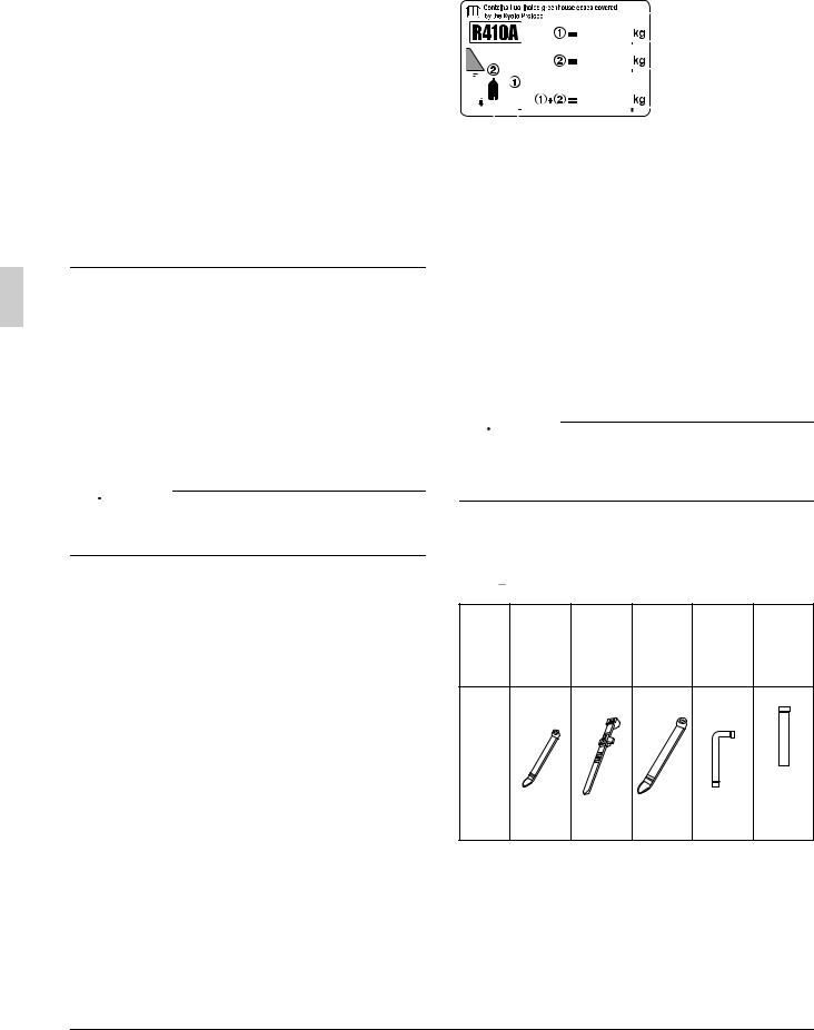
This product contains fluorinated greenhouse gases covered by the Kyoto Protocol. Do not vent gases into the atmosphere. Refrigerant type : R410A
GWP (1) value : 2090
(1) GWP = global warming potential Please fill in with indelible ink,
Q the factory refrigerant charge of the product,
Q the additional refrigerant amount charged in the field and
Q +
+  the total refrigerant charge
on the refrigerant charge label supplied with the product.
The filled out label must be adhered in the proximity of the product charging port (e.g. onto the inside of the service cover).
|
|
|
|
|
|
|
|
|
|
|
4 |
1 |
factory refrigerant charge |
|||||
|
|
|
|
|
|
|
|
|
|
|
|
|
|
|
||||
|
|
|
|
|
|
|
|
|
|
|
|
|
|
|
|
|
||
|
|
|
|
|
|
|
|
|
|
|
|
|
|
|
|
|
|
of the product : see unit |
|
|
|
|
|
|
|
|
|
|
|
|
|
|
1 |
|
name plate |
||
|
|
|
|
|
|
|
|
|
|
|
|
|
|
|
||||
|
|
|
|
|
|
|
|
|
|
|
|
|
||||||
|
|
|
|
|
|
|
|
|
|
|
|
|
|
|
|
2 |
2 |
additional refrigerant |
|
|
|
|
|
|
|
|
|
|
|
|
|
|
|
|
|||
|
|
|
|
|
|
|
|
|
|
|
|
|
|
|
amount charged in the field |
|||
|
|
|
|
|
|
|
|
|
|
|
|
|
|
|
||||
|
|
|
|
|
|
|
|
|
|
|
|
|
|
|
|
3 |
3 |
total refrigerant charge |
|
|
|
|
|
|
|
|
|
|
|
|
|
|
|
|
4 |
Contains fluorinated |
|
|
|
|
|
|
|
|
|
|
|
|
|
|
|
|
|
|
|
greenhouse gases covered |
|
6 |
5 |
|
|
|
|
|
|
|
|
|
|
|
by the Kyoto Protocol |
||||
|
|
|
|
|
|
|
|
|
|
|
|
|
|
|
|
|
5 |
outdoor unit |
|
|
|
|
|
|
|
|
|
|
|
|
|
|
|
|
|
6 |
refrigerant cylinder and |
|
|
|
|
|
|
|
|
|
|
|
|
|
|
|
|
|
|
manifold for charging |
[DESIGN PRESSURE]
Since design pressure is 3.8MPa or 38bar (for R407C units : 3.3MPa or 33bar), the wall thickness of pipes should be more carefully selected in accordance with the relevant local and national regulations.
1-3 Disposal requirements
Dismantling of the unit, treatment of the refrigerant, oil and eventual other parts, should be done in accordance with the relevant local and national regulations.
2.BEFORE INSTALLATION

 CAUTION
•When installing the indoor unit, refer to the installation manual provided for the indoor unit.
•Optional accessories are required for the installation of the product. Refer to the information on optional accessory.
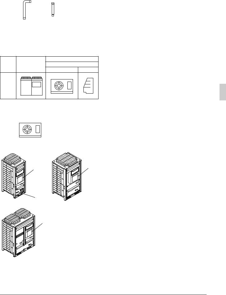
2-1 Standard supplied accessories
The following accessories are included. The storage location of the accessories is shown in the figure.
Note 

Do not throw away any of the accessories until installation is complete.
|
|
|
|
Gas side |
Gas side |
Name |
Clamp (1) |
Clamp (2) |
Clamp (3) |
acces- |
acces- |
sory pipe |
sory pipe |
||||
|
|
|
|
(1) |
(2) |
|
|
|
|
|
|
Quantity |
11 pcs. |
1 pcs. |
1 pc. |
1 pc. |
1 pc. |
Shape
|
|
Thick |
|
Small |
Large |
(included |
|
with 5.6A |
|||
|
|
||
|
|
type only) |
2 |
English |
|
Liquid side |
Liquid side |
|
Name |
accessory |
accessory |
Others |
|
pipe (1) |
pipe (2) |
|
|
|
|
|
Quantity |
1 pc. |
1 pc. |
1 pc. about each item |
|
|
|
|
|
|
|
• Operation manual |
|
|
|
• Installation manual |
Shape |
|
|
• Declaration of con- |
|
|
formity (PED) |
|
|
|
|
|
|
|
|
• “ADDITIONAL REF. |
|
|
Thin |
CHARGE” label |
|
|
|
|
2-2 Model series
MT (Medium Temperature) |
LRMEQ5~20AY1(E) |
|
|
LT (Low Temperature) |
LRLEQ5~20AY1(E) |
|
|
2-3 Example of system configuration
Indoor unit
Name |
Outdoor unit |
MT (Medium Temperature) |
|
|
|
Unit cooler |
Showcase |
Shape |
|
|
|
|
Indoor unit |
Control panel |
Warning |
||||||||||
Name |
|
|
|
|
|
|
|||||||
LT (Low Temperature) |
|||||||||||||
(Defrost) |
|
panel |
|||||||||||
|
|
|
|
|
|
|
|
||||||
|
Unit cooler |
Showcase |
|
|
|
|
|
|
|||||
|
|
|
|
|
|
|
|
|
|
|
|
|
|
Shape |
|
|
|
|
|
|
|
|
|
|
|
|
|
|
|
|
|
|
|
|
|
|
|
|
|
||
|
|
|
|
|
|
|
|
|
|
|
|
||
|
|
|
|
|
|
|
|
|
|
|
|
||
|
|
|
|
|
|
|
|
|
|
|
|
|
|
|
|
|
|
|
|
|
|
|
|
|
|
|
|
|
|
|
|
|
|
|
|
|
|
|
|
|
|
|
|
|
|
|
|
|
|
|
|
|
|
|
|
|
|
|
|
|
|
|
|
|
|
|
|
|
|
[5A, 6A type] [8A, 10A, 12A type]
1, 2, 3 |
1, 2, 3 |
|
 4
4
4
[15A, 20A type]
1, 2, 3
 4
4
1Operation manual
2Installation manual
3Clamps
4Accessory pipes (Installed on bottom frame)
2-4 Indoor unit constraints
•Install an R410A mechanical thermostatic expansion valve on each indoor unit.
•Insulate the feeler block of the mechanical thermostatic expansion valve.
•Install an R410A solenoid valve (Max. operating differential pressure of 3.5 MPa [35 bars] or over) on the primary side of the mechanical thermostatic expansion valve described above for each indoor unit.
•Install a filter on the primary side of the solenoid valve described above for each indoor unit. Determine the filter mesh count based on the size specified by the solenoid valve and mechanical thermostatic expansion valve being used.
•Route the path to the indoor unit heat exchanger so that the flow of refrigerant is from top to bottom.
•When installing a number of indoor units, be sure to install them at the same level.
•Use either off-cycle defrosting or electric heater defrosting as the defrosting type. Hot-gas defrosting models cannot be used.
3.SELECTION OF LOCATION
Select a location for installation that meets the following conditions. Get the customer’s permission.
1.There is no danger of fire due to leakage of inflammable gas.
2.Select the location of the unit in such a way that neither the discharged air nor the sound generated by the unit disturb anyone.
3.The foundation is strong enough to support the weight of the unit and the floor is flat to prevent vibration and noise generation.
4.The piping length between the outdoor unit and the indoor unit may not exceed the allowable piping length. (Refer to
“6. REFRIGERANT PIPING”)
5.Locations where the unit’s suction vent and outlet vent do not generally face the wind.
Wind blowing directly into the suction or outlet vents will interfere with the unit’s operation.
If necessary, install some kind of obstruction to block the wind.
6.The space around the unit is adequate for servicing and the minimum space for air inlet and air outlet is available.
(See the “Installation Space Examples” for the minimum space requirements.)
Installation Space Examples
•The installation space requirement shown in the following figure is a reference for cooling operation when the outdoor temperature is 32°C.
If the design outdoor temperature exceeds 32°C or the heat load exceeds maximum capacity in all the outdoor unit, take an even large space on the intake shown in the following figure.
•During installation, install the units using the most appropriate of the patterns shown in the following figure for the location in question, taking into consideration human traffic and wind.
•If the number of units installed is more than that shown in the pattern in the following figure, install the units so there are no short circuits.
•As regards space in front of the unit, consider the space needed for the local refrigerant piping when installing the units.
•If the work conditions in the following figure do not apply, contact your dealer or Daikin directly.
English |
3 |

< If installed as a single unit > |
<When installed in serial > |
|
||||||||
(Pattern 1) NOTE) |
|
(Pattern 1) NOTE) |
|
|||||||
|
|
|
|
|
<![if ! IE]> <![endif]>Service space of suction side |
|
|
|
|
<![if ! IE]> <![endif]>Service space of suction side |
|
|
<![if ! IE]> <![endif]>≥300 |
|
|
|
|
<![if ! IE]> <![endif]>≥300 |
|
||
|
|
|
|
|
|
|||||
|
|
|
|
|
|
|||||
|
|
|
|
|
|
|
|
|
||
≥10 |
≥10 |
Front
side
(Pattern 2) NOTE)
≥50 |
≥50 |
Front
side
(Pattern 3)
| <![if ! IE]> <![endif]>500≥ |
<![if ! IE]> <![endif]>spaceService sidefrontof |
≥10 |
|
Front side |
|
|
<![if ! IE]> <![endif]>500≥ |
<![if ! IE]> <![endif]>spaceService sidefrontof |
|||||||
|
|
|
|
|
|
|
|
|
|
|
|
≥10 |
|
||
|
|
|
|
|
|
|
|
|
|
|
|
|
|||
|
|
≥20 |
|
|
|
|
|
|
|
|
|
|
≥20 |
|
|
|
|
|
|
|
|
|
|
|
|
|
|
|
|
|
|
|
|
|
|
|
|
|
|
|
|
|
|
|
|
|
|
| <![if ! IE]> <![endif]>≥100 |
<![if ! IE]> <![endif]>Service space |
<![if ! IE]> <![endif]>of suction side |
| <![if ! IE]> <![endif]>≥500 |
<![if ! IE]> <![endif]>Service space |
<![if ! IE]> <![endif]>of front side |
≥50
≥100
| <![if ! IE]> <![endif]>100 |
<![if ! IE]> <![endif]>Servicespace |
<![if ! IE]> <![endif]>suctionof side |
(Pattern 2) NOTE) |
|
|
| <![if ! IE]> <![endif]>500≥ ≥ |
<![if ! IE]> <![endif]>Servicespace |
<![if ! IE]> <![endif]>frontofside |
≥50 |
|
|
≥100 |
|
|
Front side |
|
|
No limit to
wall height
(Pattern 3)
|
<![if ! IE]> <![endif]>300≥ |
No limit to |
<![if ! IE]> <![endif]>300≥ |
|
|
|
|
|
|
wall height |
|
≥200 |
|
≥200 |
|
|
≥400 |
≥400 |
|
|
|
||
|
Front side |
|
Front side |
NOTE) For Patterns 1 and 2
•Wall height for front side no higher than 1500 mm.
•Wall height on the suction side no higher than 500 mm.
•Wall height for sides – no limit
•If the height is exceeded the above, calculate h1 and h2 shown in the figure below, and add h1/2 to the service space of front side and h2/2 to the service space of suction side.
|
<![if ! IE]> <![endif]>h1 |
|
|
|
|
| <![if ! IE]> <![endif]>A |
<![if ! IE]> <![endif]>1500 |
<![if ! IE]> <![endif]>Front side |
<![if ! IE]> <![endif]>Suction side |
<![if ! IE]> <![endif]>500 h2 |
<![if ! IE]> <![endif]>B |
Service space
Service space
h1 = A (Actual height) – 1500
h2 = B (Actual height) – 500 X = 500 + h1/2 or over
Y = 300 + h2/2 or over (Y = 100 + h2/2 or over)
[Values in parentheses are for pattern 2]

 CAUTION
Branch switch, |
|
|
|
|
Control panel |
overcurrent breaker |
|
|
|
|
|
|
|
|
|
Warning panel |
|
(Earth leakage breaker) |
|
|
|
|
|
|
|
|
|
Branch switch, |
|
|
|
|
|
|
|
|
|
|
|
|
overcurrent breaker |
|
|
|
|
|
(Earth leakage breaker) |
|
≥ |
1500 |
|
1500 |
|
|
|
|
|
||
|
|
|
≥ |
|
≥1500 |
≥ |
|
|
|
|
|
|
|
|
|
≥1500 |
|
1500 |
|
|
|
|
|
Showcase |
|
|
|
|
(mm) |
1.An inverter condensing unit may cause electronic noise generated from AM broadcasting. Examine where to install the main condensing unit and electric wires, keeping proper distances away from stereo equipment, personal computers, etc. Particularly for locations with weak reception, ensure there is a distance of at least 3 meters for indoor remote controllers, place power wiring and transmission wiring in conduits, and ground the conduits.
2.When installing in a locations where there is heavy snowfall, implement the following snow measures.
•Ensure the base is high enough that intakes are not clogged by snow.
•Mount a snow protection hood (optional accessory)
•Remove the rear intake grille to prevent snow from accumulating on the fins.
3.If condensate may drip on downstairs (or walkway) depending on the floor condition, take a measure such as the installation of central drain pan kit (sold separately).
4.The refrigerant R410A itself is nontoxic, nonflammable and is safe. If the refrigerant should leak however, its concentration may exceed the allowable limit depending on room size. Due to this it could be necessary to take measures against leakage.
See “Engineering Data” for details.
4.HANDLING THE UNIT
1.Decide on the transportation route.
2.If a forklift is to be used, pass the forklift arms through the large openings on the bottom of the unit.
1
4
2 |
3 |
1Opening (large)
2Fork
3Fixed screws of transportation clasp
4Transportation clasp (yellow)
If hanging the unit, use a cloth sling to prevent damaging the unit. Keeping the following points in mind, hang the unit following the procedure shown in the following figure.
• Use a sling sufficiently strong to hold the mass of the unit.
• Use 2 belts of at least 8m long.
• Place extra cloth in the locations where the casing comes in contact with the sling to prevent damage.
• Hoist the unit making sure it is being lifted at its center of gravity.
1 2
4
5
6
3
1Belt sling
2Patch cloth
3Opening (large)
Used for size 5A or 6A
4Belt sling
5Patch cloth
4 |
English |

6Opening (small)
Used for size 8A, 10A, 12A, 15A, or 20A
3.After installation, remove the transportation clasp (yellow) attached to the large openings.
Note 

Apply a filler cloth on a fork to prevent coating of the bottom frame from coming off and rust from occurring when bringing in the unit with anti-corrosion treatment type using a forklift.
5.PLACING THE UNIT
•Make sure the unit is installed level on a sufficiently strong base to prevent vibration and noise.
•The base should be bigger around than the width of the unit’s legs (66 mm), and should support the unit.
If protective rubber is to be attached, attach it to the whole face of the base.
•The height of the base should be at least 150mm from the floor.
•Secure the unit to its base using foundation bolts. (Use four commercially available M12-type foundation bolts, nuts, and washers.)
•The foundation bolts should be inserted 20 mm.
<![if ! IE]><![endif]>20
Corner-hole |
Independent |
Beam |
Beam |
|
|
foundation |
foundation |
foundation |
foundation |
||
|
|
|
(horizontal) |
(vertical) |
|
|
|
≥100 |
|
≥100 |
|
|
|
|
|
|
|
|
|
Not required |
|
Not required |
|
|
≥100 |
for size |
≥100 |
|
for size |
|
≥100 |
5A or 6A |
100 |
5A or 6A |
|
|
≥ |
|
|||
|
Center of the product |
Center of the product |
|
||
|
The corner-hole foundation that secures the unit with the holes on the |
|
|||
|
four corners is not available to size 8A, 10A, 12A, 15A, 20A. |
|
|
||
|
The corner-hole foundation, however, is available to size 5A and 6A. |
|
|||
|
|
Base form |
|
|
|
|
|
|
Foundation bolt point |
||
|
|
A |
(4-15 × 22.5) |
|
|
|
|
B |
|
|
|
| <![if ! IE]> <![endif]>765 (Depth of product) |
<![if ! IE]> <![endif]>729 |
|
<![if ! IE]> <![endif]>631 |
<![if ! IE]> <![endif]>(Inner dimension of the base) 765 or more (Outer dimension of the base) |
|
|
|
|
|
(Unit : mm) |
|
|
Model |
A |
B |
|
|
|
5A · 6A type |
635 |
497 |
|
|
|
8A · 10A · 12A type |
930 |
792 |
|
|
|
15A · 20A type |
1240 |
1102 |
|
|
Base width and base bolt positions
Note 

•When installing on a roof, make sure the roof floor is strong enough and be sure to water-proof all work.
•Make sure the area around the machine drains properly by setting up drainage grooves around the foundation.
Drain water is sometimes discharged from the outdoor unit when it is running.
• If the condensing unit is of brine damage resistant or heavy brine damage resistant type, use nuts provided with resin washers to secure the product to the foundation bolts (see the illustration on the right-hand side).
The rustproof effect of the nut will be lost if the coatings on the tightening portions of the nuts come off.
6.REFRIGERANT PIPING
To Piping Work Contractors
•Never open the shutoff valve until the steps specified in “7. FIELD WIRING” and “8-3 Checking of device and installation conditions” of piping.
•Do not use flux at the time of brazing and connecting refrigerant pipes. Use phosphorous copper brazing filler metal (BCuP-2), which does not require flux. Chlorine-based flux causes piping corrosion. Furthermore, if fluoride is contained, the flux will have adverse influences on the refrigerant piping line, such as the deterioration of refrigerating machine oil.

 CAUTION
•All field piping must be installed by a licensed refrigeration technician and must comply with relevant local and national regulations.
[Precautions for reuse of existing refrigerant piping / heat exchangers]
Keep the following points in mind for the reuse of existing refrigerant piping / heat exchangers.
A malfunction may result if there is deficiency.
•Do not use the existing piping in the following cases. Perform new piping instead.
•The piping is different in size.
•The strength of the piping is insufficient.
•The compressor of the condensing unit previously used caused a malfunction.
An adverse influence of residual substances, such as the oxidation of refrigerant oil and the generation of scale, is considered.
•If the indoor unit or outdoor unit is disconnected from the piping for a long time.
The intrusion of water and dust into the piping is considered.
•The copper pipe is corroded.
•The refrigerant of the condensing unit previously used was other than R410A (e.g., R404A / R507 or R407C).
The contamination of the refrigerant with heterogeneity is considered.
•If there are welded connections midway on the local piping, make gas leakage checks on the welded connections.
•Be sure to insulate the connection piping.
The liquid and gas pipe temperatures are as follows: Liquid pipe arrival minimum temperature: 0°C
Gas pipe arrival minimum temperature: –26°C (Refrigeration Series)
–46°C (Freezer Series)
In the case of thickness insufficiency, add additional insulation material or renew the existing insulation material.
•Renew the insulation material if the insulation material is
degraded.
Keep the following points in mind for the reuse of existing heat exchangers
•Units with insufficient design pressure (since this product is an R410A unit) require a lower-stage design pressure of 2.5 MPa [25 bars].
•Units for which the path to the heat exchanger has been routed so that the flow of refrigerant is from bottom to top
•Units with copper tubing or fan corrosion
•Units that may be contaminated with foreign matter such as rubbish or other dirt
English |
5 |
6-1 Selection of Piping Material
•Make sure that the inner side and outer side of the piping used is clean and free of contaminants, such as sulphur, oxide, dust, chips, oil and fat, and water. It is desirable that the maximum oil adhesion in the piping is 30 mg per 10 m.
•Use the following type of refrigerant piping.
Material: Seamless phosphorus deoxidized copper tube (C1220T-O for a maximum outer diameter of 15.9 mm and C1220T-1/2H for a minimum outer diameter of 19.1 mm)
Refrigerant piping size and wall thickness: Decide the size and thickness from the following table.
(This product uses R410A. The withstand pressure of O type may be insufficient if it is used for piping with a minimum diameter of 19.1 mm. Therefore, be sure to use 1/2 H type with a minimum thickness of 1.0 mm.
If O type is used for piping with a minimum diameter of 19.1 mm, a minimum thickness of 1.2 mm will be required. In that case, be sure to perform the blazing of each joint.)
• Be sure to perform piping work within the range specified in the following table.
Refrigerant piping length |
|
|
|
|
|
Outdoor unit |
||
|
|
|
|
|
|
|
||
Max. permissible |
LRMEQ5~20AY1 |
a + b + c + d ≤ 130m (d is d1 or d2 whichever is longer) |
|
|
|
|
|
|
one-way piping length |
|
a + b + c + d ≤ 70m (d is d1 or d2 whichever is longer) |
|
|
Liquid piping |
|
||
(equivalent length) |
LRLEQ5~20AY1 |
|
|
|
||||
|
|
A |
B |
C |
D2 |
|||
|
|
|
|
<![if ! IE]> <![endif]>piping |
||||
Max. branch piping length (actual length) |
b + c + d ≤ 30m (d is d1 or d2 whichever is longer) |
H |
F |
E |
D1 |
|
||
|
|
|||||||
|
|
|
|
|
||||
Max. difference in |
unit below outdoor unit |
H ≤ 35m (Note) |
|
<![if ! IE]> <![endif]>Gas |
|
|
|
|
height between indoor |
|
H ≤ 10m |
|
Showcase |
|
|||
and outdoor units |
unit above outdoor unit |
|
|
|
||||
|
|
|
|
H1 |
Unit |
|||
|
|
|
|
|
|
|
||
Difference in height between indoor units |
H1 ≤ 0.5m |
|
|
f |
e |
d1 |
cooler |
|
|
|
|
|
|
|
|||
|
Note: A trap is required at 5 m intervals from outdoor unit. |
|
|
a |
b |
c |
d2 |
|
Refrigerant piping size |
|
|
|
|
|
|
|
|
(MT (Medium Temperature)) LRMEQ5~20AY1 |
|
|
|
|
(Unit : mm) |
|||
|
|
|
|
|
|
|
|
|
|
Piping size |
|
|
|
|
|
|
|
Outdoor unit side |
Liquid pipe |
|
|
Gas pipe |
|
|
||
|
50m or less |
50~130m |
50m or less |
50~130m |
||||
5A · 6A type |
φ9.5 × 0.8 (O type) |
φ12.7 × 0.8 (O type) |
φ19.1 × 1.0 (1/2H type) |
φ22.2 × 1.0 (1/2H type) |
||||
8A · 10A · 12A type |
φ9.5 × 0.8 (O type) |
φ12.7 × 0.8 (O type) |
φ25.4 × 1.0 (1/2H type) |
φ28.6 × 1.0 (1/2H type) |
||||
15A · 20A type |
φ12.7 × 0.8 (O type) |
φ15.9 × 0.8 (O type) |
φ31.8 × 1.1 (1/2H type) |
φ34.9 × 1.1 (1/2H type) |
||||
Piping between branching areas |
Select the piping from the following table in accordance with the total capacity of indoor units |
|||||||
(B, b, C, c) |
connected downstream. |
|
|
|
|
|||
|
|
|
|
|
|
|
|
|
|
|
Total capacity of indoor units after branching |
|
Gas pipe size |
|
Liquid pipe size |
|
|
|
|
Less than 6.0 kW |
|
|
φ12.7 × 0.8 (O type) |
|
φ6.4 × 0.8 (O type) |
|
|
|
6.0 kW or over and less than 9.9 kW |
|
φ15.9 × 1.0 (1/2H type) |
|
|
|
|
|
|
9.9 kW or over and less than 14.5 kW |
|
φ19.1 × 1.0 (1/2H type) |
|
φ9.5 × 0.8 (O type) |
|
|
|
|
14.5 kW or over and less than 18.5 kW |
|
φ22.2 × 1.0 (1/2H type) |
|
|
||
|
|
|
|
|
|
|||
|
|
18.5 kW or over and less than 25.0 kW |
|
φ25.4 × 1.0 (1/2H type) |
|
|
|
|
|
|
25.0 kW or over and less than 31.0 kW |
|
φ28.6 × 1.0 (1/2H type) |
|
φ12.7 × 0.8 (O type) |
|
|
|
|
31.0 kW or over |
|
|
φ31.8 × 1.1 (1/2H type) |
|
|
|
|
|
|
|
|
|
|
||
|
No size after branching can exceed the size of any upstream piping. |
|
|
|||||
|
|
|
|
|
|
|||
Piping between branching areas and each unit |
Adjust the size of the piping so that it will coincide with the size of piping connecting to the indoor unit. |
|||||||
|
|
|
|
|
|
|
|
|
(LT (Low Temperature)) LRLEQ5~20AY1 |
|
|
|
|
(Unit : mm) |
|||
|
|
|
|
|
|
|
|
|
|
Piping size |
|
|
|
|
|
|
|
Outdoor unit side |
Liquid pipe |
|
|
Gas pipe |
|
|
||
|
50m or less |
50~70m |
25m or less |
25~70mm |
||||
5A · 6A type |
φ9.5 × 0.8 (O type) |
φ12.7 × 0.8 (O type) |
φ19.1 × 1.0 (1/2H type) |
φ22.2 × 1.0 (1/2H type) |
||||
8A · 10A · 12A type |
φ9.5 × 0.8 (O type) |
φ12.7 × 0.8 (O type) |
φ25.4 × 1.0 (1/2H type) |
φ28.6 × 1.0 (1/2H type) |
||||
15A · 20A type |
φ12.7 × 0.8 (O type) |
φ15.9 × 0.8 (O type) |
φ31.8 × 1.1 (1/2H type) |
φ34.9 × 1.1 (1/2H type) |
||||
Piping between branching areas |
Select the piping from the following table in accordance with the total capacity of indoor units |
|||||||
(B, b, C, c) |
connected downstream. |
|
|
|
|
|||
|
|
|
|
|
||||
|
|
Total capacity of indoor units after branching |
|
Gas pipe size |
|
Liquid pipe size |
|
|
|
|
Less than 2.3 kW |
|
|
φ12.7 × 0.8 (O type) |
|
φ6.4 × 0.8 (O type) |
|
|
|
2.3 kW or over and less than 4.4 kW |
|
φ15.9 × 1.0 (1/2H type) |
|
|
|
|
|
|
4.4 kW or over and less than 6.4 kW |
|
φ19.1 × 1.0 (1/2H type) |
|
φ9.5 × 0.8 (O type) |
|
|
|
|
6.4 kW or over and less than 7.8 kW |
|
φ22.2 × 1.0 (1/2H type) |
|
|
||
|
|
|
|
|
|
|||
|
|
7.8 kW or over and less than 10.8 kW |
|
φ25.4 × 1.0 (1/2H type) |
|
|
|
|
|
|
10.8 kW or over and less than 13.4 kW |
|
φ28.6 × 1.0 (1/2H type) |
|
φ12.7 × 0.8 (O type) |
|
|
|
|
13.4 kW or over |
|
|
φ31.8 × 1.1 (1/2H type) |
|
|
|
|
|
|
|
|
|
|
||
|
No size after branching can exceed the size of any upstream piping. |
|
|
|||||
|
|
|||||||
Piping between branching areas and each unit |
Adjust the size of the piping so that it will coincide with the size of piping connecting to the indoor unit. |
|||||||
|
|
|
|
|
|
|
|
|
6 |
English |

6-2 Protection against contamination when installing pipes
Protect the piping to prevent moisture, dirt, dust, etc. from entering the piping.
Place |
Installation period |
Protection method |
|
|
|
|
|
Outdoor |
More than a month |
Pinch the pipe |
|
|
|
||
Less than a month |
Pinch or tape the pipe |
||
|
|||
|
|
||
Indoor |
Regardless of the period |
||
|
|||
|
|
|
Note 

Exercise special caution to prevent dirt or dust when passing piping through holes in walls and when passing pipe edges to the exterior.
6-3 Pipe connection
• Be sure to perform nitrogen permutation or nitrogen blow when brazing.
Refrigerant pipe |
|
Location to |
Regulator |
be brazed |
|
Nitrogen
Taping
Handy valve
Nitrogen
Brazing without performing nitrogen permutation or nitrogen blow into the piping will create large quantities of oxidized film on the inside of the pipes, adversely affecting valves and compressors in the refrigerating system and preventing normal operation.
•The pressure regulator for the nitrogen released when doing the brazing should be set to 0.02 MPa (about 0.2kg/cm2:Enough to feel a slight breeze on your cheek).
Note 

Do not use anti-oxidants when brazing the pipe joints. Residue can clog pipes and break equipment.
6-4 Drier installation

 CAUTION
This product requires that a drier be installed on liquid piping on site. (Operating the unit without a drier installed may result in equipment failure.)
Select a drier from the following chart:
Model |
Required dryer core |
|
(recommended type) |
||
|
||
|
|
|
LRMEQ5AY1, LRLEQ5AY1 |
80g (100% molecular sieve equivalent) |
|
LRMEQ6AY1, LRLEQ6AY1 |
(DML083/DML083S : Danfoss made) |
LRMEQ8AY1, LRLEQ8AY1
160g (100% molecular sieve equivalent) LRMEQ10AY1, LRLEQ10AY1 (DML163/DML163S : Danfoss made) LRMEQ12AY1, LRLEQ12AY1
LRMEQ15AY1, LRLEQ15AY1 160g (100% molecular sieve equivalent) LRMEQ20AY1, LRLEQ20AY1 (DML164/DML164S : Danfoss made)
•Install the drier in a horizontal orientation wherever possible.
•Install the drier as close to the outdoor unit as possible.
•Remove the drier cap immediately before brazing (to prevent absorption of airborne moisture).
•Follow instructions in the drier instruction manual concerning drier brazing.
•Repair any burning of drier paint that occurs during drier brazing. Contact the manufacturer for more information about paint for repair use.
•Flow direction is specified for some type of the dryer.
Set the flow direction according to the operation manual of the dryer.
6-5 Connecting the refrigerant piping

 CAUTION
•In addition to gas and liquid shutoff valves, this unit has a maintenance shutoff valve (see diagram below).
•Do not operate the maintenance shutoff valve*.
(The factory setting for the maintenance shutoff valve is “open.” During operation, always leave this valve in the open position. Operating the unit with the valve in the closed position may cause the compressor to fail.)
*Maintenance shutoff valve
* Maintenance shutoff valve
Liquid side shutoff valve (provided with service port)
Gas side shutoff valve (provided with service port)
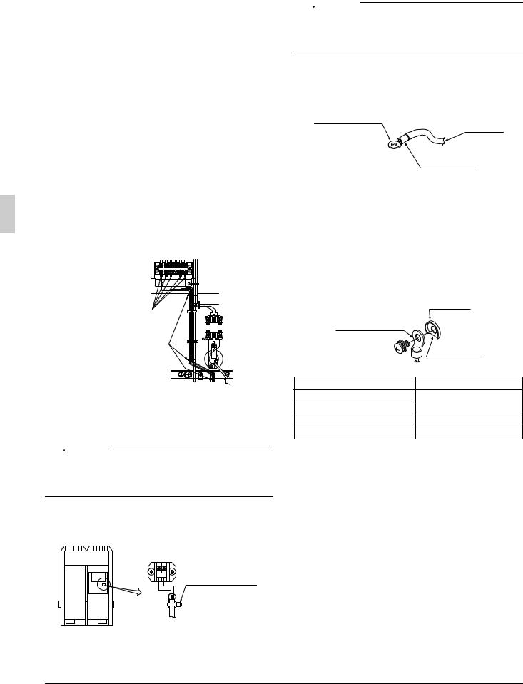
1.Directions to bring out the pipes
The local interunit piping can be connected either forward or to the sides (taken out through the bottom) as shown in the following figure. When passing out through the bottom, use the knock hole in the bottom frame.
Right-side connection
Front connection
Left-side connection
Precautions when knocking out knock holes
•Open knock hole in the base frame by drilling the 4 concave around it with a 6mm bit.
Knock hole |
Drill |
Concave section (4 places)
•Be sure to avoid damaging the casing
•After knocking out the holes, we recommend you remove any burrs and paint them using the repair paint to prevent rusting.
•When passing electrical wiring through the knock holes, protect the wiring with a conduit or bushings, making sure not to damage the wiring.
English |
7 |

2.Removing Pinch Piping
In the case of connecting refrigerant piping to the outdoor unit, remove the span piping as in the following procedure.
Refer to “Operation method of shutoff valve” for handling of the shutoff valve.
Liquid side and gas side shutoff valves
Procedure 1 |
Service port |
|
Procedure 2 |
||
Confirm the shutoff |
||
Connect a charge hose to |
||
valve is closed. |
||
the service port of the liquid |
||
|
||
Procedure 4 |
side and gas side shutoff |
|
valves and remove the gas |
||
Melt the brazing |
||
from the pinch piping. |
||
material with a burner |
||
|
||
and remove the pinch |
|
|
piping (large) after the |
Pinch piping |
|
gas in the pinch |
|
|
piping is discharged. |
|
Piping on product side
Charge hose
Service port
On-site piping
Pinch piping (Large)
Pinch piping (Small)
Cut off
Procedure 3
Cut off the pinch piping (small) with an appropriate tool, such as a pipe cutter, and open the cross section to check that there is no residual oil.
Note: If oil comes out of the cross section, cut off the pinch piping (large) with a pipe cutter and remove the pinch piping.


 WARNING
Disconnect the pinch piping after collecting the refrigerant gas in the piping.
The piping may be blown off and injury may result by melting the brazing filler metal unless the refrigerant gas in the piping is all collected.
Operation Method of Shutoff Valves
Follow the instructions below when operating each shutoff valve.

 CAUTION
•Do not open the shutoff valve until the steps specified in
“8-3 Checking of device and installation conditions” is completed.
Do not leave the shutoff valve opened without turning the power on, otherwise refrigerant may be condensed in the compressor and the insulation of the main power supply circuit may be degraded.
•Be sure to use an exclusive tool to handle the shutoff valve. The shutoff valve is not of back sheet type. Excessive force imposed may break the valve.
•Use a charge hose when using the service port.
•Make sure that there is no refrigerant gas leakage after the valve cover and cap are securely tightened.
Tightening torque
Check with the following table the sizes of shutoff valves incorporated by each model and the tightening torque values of the respective shutoff valves.
Shutoff valve sizes
 5A type 6A type 8A type 10A type 12A type 15A type 20A type
Liquid side |
|
φ9.5 |
φ12.7 |
|
shutoff valve |
|
|||
|
|
|
||
|
|
|
|
|
Gas side |
φ19.1 |
φ25.4 |
φ31.8 |
|
shutoff valve |
||||
|
|
|
||
|
|
|
|
Service port
Valve cover
|
|
|
|
Hexagon hole |
|
Sealing part |
|
Shaft |
|
||
|
|
|
|
||
|
|
|
|
|
|
Shutoff |
Tightening torque N•m (closes clockwise) |
||||
valve sizes |
Shaft (valve body) |
|
Valve cover |
Service port |
|
|
|
|
|
|
|
φ9.5 |
5.4~6.5 |
Hexagon |
|
13.5~16.5 |
|
φ12.7 |
8.1~9.9 |
wrench: 4mm |
|
18.0~22.0 |
|
|
|
|
|
|
|
φ19.1 |
27.0~33.0 |
Hexagon |
|
22.5~27.5 |
11.5~13.9 |
φ25.4 |
wrench: 8mm |
|
|||
|
|
|
|
||
|
|
|
|
|
|
φ31.8 |
26.5~29.4 |
Hexagon |
|
44.1~53.9 |
|
wrench: 10mm |
|
|
|||
|
|
|
|
|
|
|
|
|
|
|
|
Opening method
1.Remove the valve cover and turn the shaft anticlockwise with a hexagon wrench.
2.Turn the shaft until the shaft stops.
3.Tighten the valve cover securely. Refer to the above table for the tightening torque according to the size.
Closing method
1.Remove the valve cover and turn the shaft clockwise with a hexagon wrench.
2.Tighten the shaft until the shaft comes in contact with the sealing part of the valve.
3.Tighten the valve cover securely. Refer to the above table for the tightening torque according to the size.
Handling Precautions for Valve Cover
•Be careful not to damage the sealing part.
•At the time of mounting the valve cover, apply a screw lock agent to the screw thread.
•Do not apply a screw lock agent (for flare nut use) to the sealing part.
•Be sure to tighten the valve cover securely after operating the valve. Refer to “Operation Method of Shutoff Valves” for the tightening torque of the valve.
Screw thread
Apply a screw lock agent
Valve cover
|
Shutoff valve |
|
Part of mounting the |
Sealing part |
valve cover. |
Not apply a screw lock agent |
|
|
|
|
|
|
|
8 |
English |
Handling Precautions for Service Port
•Work on the service port with a charge hose provided with a pushing rod.
•At the time of mounting the cap, apply a screw lock agent to the screw thread.
•Do not apply a screw lock agent (for flare nut use) to the sealing part.
•Be sure to tighten the cap securely after the work. Refer to “Operation Method of Shutoff Valves” for the tightening torque of the cap.
|
Cap |
Sealing part |
|
Not apply a screw |
Screw thread |
lock agent |
Apply a screw lock |
|
agent |

 CAUTION
Apply a screw lock agent to the valve cover mount and the screw thread of the service port.
Otherwise, dew condensation water will intrude inside and freeze. Therefore, refrigerant gas leakage or a compressor malfunction may result from the cap deformation or damage.
3.Connecting refrigerant piping to outdoor units
If connected to the front
Remove the shutoff valve cover to connect.
Liquid side shutoff valve
Gas side shutoff valve
Gas side |
Brazing |
accessory pipe (1) |
|
Liquid side accessory pipe (1)
When connected at lateral side (bottom)
Remove the knock hole on the bottom frame and route the piping under the bottom frame.
[5A, 6A type] |
|
|
Gas side |
Liquid side |
|
shutoff valve |
||
shutoff valve |
||
|
Brazing |
|
Gas side |
Knockout hole |
|
accessory pipe (2) |
||
Punch the knock |
||
|
||
Brazing |
hole. |
|
|
||
Liquid side piping |
|
|
(field supply) |
Liquid side |
|
|
accessory pipe (2) |
Gas side piping (field supply)
[8A, 10A, 12A, 15A, 20A type]
Gas side |
Liquid side |
|
shutoff valve |
||
shutoff valve |
||
|
Brazing |
|
Gas side |
Knockout hole |
|
accessory pipe (1) |
||
Punch the knock |
||
|
||
Brazing |
hole. |
|
|
||
Liquid side piping |
|
|
(field supply) |
Liquid side |
|
|
accessory pipe (2) |
Gas side piping (field supply)

 CAUTION
•Check that the on-site piping does not come in contact with other piping, the bottom frame, or side plate of the product.
Precautions for Piping
Perform piping branching with the following conditions kept in mind.
•At the time of branching the liquid piping, use a T-joint or Y-joint and branch it horizontally. This will prevent an uneven flow of refrigerant.
•At the time of branching gas piping, use a T-joint and branch it so that the branched piping will be located above the main piping (see the illustration below). This will prevent the stay of refrigerant oil in the indoor unit not in operation.
•Use a Y-joint for the liquid refrigerant branch and have the piping branch horizontally.
Y-joint |
Horizontal |
|
|
surface |
±30˚ or less |
|
|
|
A |
A-arrow view |
|
|
|
•Use a T-joint for the gas refrigerant branch and connect from the top of the main piping.
T-joint
Main piping |
|
|
|
Indoor unit side |
|
|
|
Branch piping |
|
T-joint |
Make the piping |
|
slant downward |
|
|
|
|
|
|
Main piping |
|
|
Make the piping |
Branch piping |
|
slant downward |
|
|
|
Make the piping |
|
Outdoor unit side |
slant downward |
|
|
|
|
|
•Make sure that the horizontal portion of the gas piping slants downward to the outdoor unit (see the illustration above).
•If the outdoor unit is located above, make a trap on the gas pipe at 5 m intervals from outdoor unit. This will ensure the smooth returning of oil in the piping slanting upward.
English |
9 |
7.FIELD WIRING
To Electric Engineering Contractors
•Be sure to install an earth leakage breaker. The product incorporates inverter equipment. In order to prevent the malfunctioning of the earth leakage breaker, make sure that the earth leakage breaker withstands harmonic interference.
•Do not operate the condensing unit until refrigerant piping work is completed, or otherwise the compressor will malfunction.
•Do not remove any electrical components such as thermistors or sensors when connecting power supply wires or transmission wires. The compressor may malfunction if the condensing unit is operated with such electrical components removed.

 CAUTION
•All field wiring and components must be installed by a licensed electrician and must comply with relevant local and national regulations.
•Be sure to use a dedicated power circuit. Never use a power supply shared by another appliance.
•Never install a phase advancing capacitor. As this unit is equipped with an inverter, installing a phase advancing capacitor will not only deteriorate power factor improvement effect, but also may cause capacitor abnormal heating accident due to high-frequency waves.
•Only proceed with wiring work after blocking off all power.
•Always ground wires in accordance with relevant local and national regulations.
•This machine includes an inverter device. Connect earth and leave charge to eliminate the impact on other devices by reducing noise generated from the inverter device and to prevent leaked current from being charged in the outer hull of the product.
•Do not connect the ground wire to gas pipes, sewage pipes, lightning rods, or telephone ground wires.
Gas pipes: can explode or catch fire if there is a gas leak. Sewage pipes: no grounding effect is possible if hard plastic piping is used.
Telephone ground wires and lightning rods: dangerous when struck by lightning due to abnormal rise in electrical potential in the grounding.
•Be sure to install an earth leakage circuit breaker.
This unit uses an inverter, so install the earth leakage circuit breaker that be capable of handling high harmonics in order to prevent malfunctioning of the earth leakage circuit breaker itself.
•Earth leakage circuit breaker which are especially for protecting ground-faults should be used in conjunction with main switch or fuse for use with wiring.
•Electrical wiring must be done in accordance with the wiring diagrams and the description herein.
•Do not operate until refrigerant piping work is completed.
(If operated before complete the piping work, the compressor may be broken down.)
•Never remove thermistor, sensor or etc. when connecting power wiring and transmission wiring.
(If operated with thermistor, sensor or etc. removed, the compressor may be broken down.)
•This product have reversed phase protection detector that only works when the power is turned on. If there exists black out or the power goes on and off which the product is operating, attach a reversed phase protection circuit. Running the product in reversed phase may break the compressor and other parts.
•Attach the power wire securely. Introducing power with a missing N-phase or with a mistaken N-phase will break the unit.
•Never connect the power supply in reversed phase. The unit can not operate normally in reversed phase.
If you connect in reversed phase, replace two of the three phases.
•Make sure the electrical unbalance ratio is no greater than 2%. If it is larger than this, the unit’s lifespan will be reduced.
If the ratio exceeds 4%, the unit will shut down and an malfunction code will be displayed on the indoor remote controller.
•Connect the wire securely using designated wire and fix it with attached clamp without applying external pressure on the terminal parts (terminal for power wiring, terminal for transmission wiring and earth terminal).
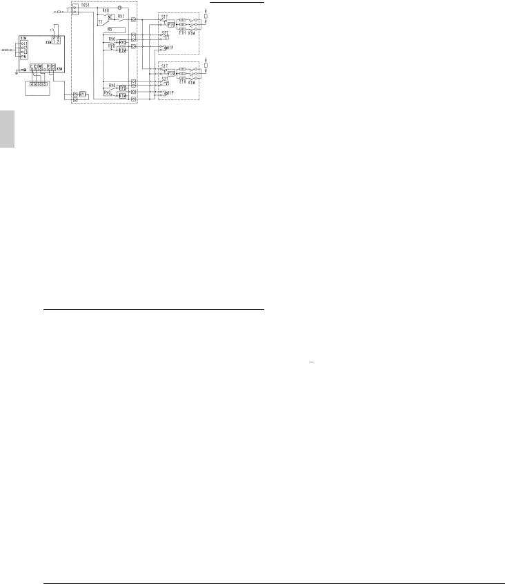
7-1 Example of Wiring Entire System
T1 |
|
Timer |
|
|
|
|
|
Ry0, Ry1 |
|
Relay |
|
|
|
|
|
K1M |
|
Electromagnetic contactor (Defrosting heater) |
|
|
|
|
|
E1H |
|
Defrosting heater |
|
|
|
|
|
S1T |
|
Thermostat for inner temperature adjustment |
|
|
|
|
|
S2T |
|
Defrost completion thermostat |
|
|
|
|
|
Y1S |
|
Solenoid valve |
|
|
|
|
|
H1P |
|
Defrost lamp |
|
|
|
|
|
|
|
9 |
|
|
|
3 |
11 |
|
|
10 |
13 |
|
|
|
|
2 |
4 |
|
|
1 |
|
|
|
|
5 |
|
12 |
|
|
|
14 |
6 7
8
Note: 1. For Remote switch, use non-voltage contact for microcurrent (not more than 1mA, 12VDC)
Note: 2. Total capacity for warning, alarm : 1A or less at AC 220 to 240V.
Capacity for operation output : 1A or less at AC 220 to 240V.
13 phase 380~415V
Earth leakage circuit breaker (High-frequency type) (for earth fault, overload, and short-circuit protection)
2Outdoor unit
3Earth leakage circuit breaker (for earth fault, overload, and shortcircuit protection)
4Note: 1 Remote switch
5High-voltage AC 220~240 V (See Note 2.) Warning output
Alarm output Operation output
6Warning input
7Alarm input
8Alarm panel
9Control board (field supply)
10Timer
11Indoor unit
12Indoor unit
13Earth leakage circuit breaker
14Earth leakage circuit breaker
Note 

•Use conduit for power supply wiring.
•Make sure the weak electric wiring (i.e. for the remote controller, between units, etc.) and the power wiring do not pass near each other, keeping them at least 50 mm apart.
Proximity may cause electrical interference, malfunctions, and breakage.
•Be sure to connect the power wiring to the power wiring terminal block and secure it as described in “7-2 Procedure for Incoming Wiring”.
•Do not connect the power supply to the terminal block for the transmission wiring for warning, alarm, operation output, and remote operation switch. Otherwise the entire system will be damaged.
•Transmission wiring should be secured as described in “7-3 Procedure for Power Supply Wiring”.
•Secure wiring with clamp such as insulation lock ties to avoid contact with piping.
•Shape the wires to prevent the structure such as the control box lid deforming. And close the cover firmly.
10 |
English |

7-2 Procedure for Incoming Wiring
•Route high-voltage wiring (power supply wiring, earth wires, and warning/alarm/operation wiring) through wiring openings located on the side or front of the unit (knock holes) or on the bottom frame (knock holes).
•Route low-voltage wiring (for remote operating switches) through wiring openings (knock holes) located on the front of the unit or through wiring intakes.
Electric wiring label (Rear side of control box lid)
Through-hole cover Cut the shaded area
High-voltage wiring
Piping outlet
Conduit
Low-voltage wiring
Note 

•Open the knock holes with a hammer or the like.
•After knocking out the holes, we recommend you remove any burrs and paint them using the repair paint to prevent rusting.
•When passing electrical wiring through the knock holes, protect the wiring with a conduit or bushings, making sure not to damage the wiring.
•If small animals might enter the unit, block off any gaps (hatching parts) with material (field supply).
Knockout hole
(For low-voltage wiring)
Knockout hole
(For high-voltage wiring) 
Burr
7-3 Procedure for Power Supply Wiring
Procedure for Power Supply Wiring
1
2
B
3
4
5 |
L 1 L 2 L 3 N |
10 |
|
9 |
8
6
7
1Power supply (3 phase 380~415)
2Branch switch or overcurrent circuit breaker (earth leakage circuit breaker)
3Earth wire
4Power supply terminal block
5Mount insulation sleeves
6Fix the power supply wiring for phases L1, L2, L3, and N, respectively, with the provided clamp (1) to the resin clamp.
7Fix the earth wire to the power supply wire (phase N) with the provided clamp (1).
8Earth wire
Perform wiring so that the earth wire will not come in contact with lead wires of the compressor. Otherwise, noise generated may have a bad influence on other equipment.
9Ground terminal
10• When two wires are connected to a single terminal, connect them so that the rear sides of the crimp contacts face each other.
•Also, make sure the thinner wire is on top, securing the two wires simultaneously to the resin hook using the accessory clamp (1).
|
Clamp (1) |
Terminal block |
Crip style terminal Wire: narrow |
|
Wire: thick |
|
Resin hook |
Power circuit, safety device, and cable requirements
•A power circuit (see the following table) must be provided for connection of the unit. This circuit must be protected with the required safety devices, i.e. a main switch, a slow blow fuse on each phase and an earth leakage circuit breaker.
•When using residual current operated circuit breakers, be sure to use a high-speed type (1 second or less) 200mA rated residual operating current.
•Use copper conductors only.
•Use insulated wire for the power cord.
•Select the power supply cable type and size in accordance with relevant local and national regulations.
•Specifications for local wiring are in compliance with IEC60245.
•Use wire type H05VV when protected pipes are used.
•Use wire type H07RN-F when protected pipes are not used.
|
Phase and |
|
Minimum |
Recom- |
|
|
Voltage |
circuit |
mended |
||
|
frequency |
||||
|
|
amp. |
fuses |
||
|
|
|
|||
|
|
|
|
|
|
LRMEQ5AY1 |
φ3, 50Hz |
380-415V |
12.7A |
15A |
|
LRLEQ5AY1 |
|||||
|
|
|
|
||
|
|
|
|
|
|
LRMEQ6AY1 |
φ3, 50Hz |
380-415V |
13.6A |
15A |
|
LRLEQ6AY1 |
|||||
|
|
|
|
||
|
|
|
|
|
|
LRMEQ8AY1 |
φ3, 50Hz |
380-415V |
19.2A |
25A |
|
LRLEQ8AY1 |
|||||
|
|
|
|
||
|
|
|
|
|
|
LRMEQ10AY1 |
φ3, 50Hz |
380-415V |
21.9A |
25A |
|
LRLEQ10AY1 |
|||||
|
|
|
|
||
|
|
|
|
|
|
LRMEQ12AY1 |
φ3, 50Hz |
380-415V |
23.9A |
25A |
|
LRLEQ12AY1 |
|||||
|
|
|
|
||
|
|
|
|
|
|
LRMEQ15AY1 |
φ3, 50Hz |
380-415V |
31.2A |
40A |
|
LRLEQ15AY1 |
|||||
|
|
|
|
||
|
|
|
|
|
|
LRMEQ20AY1 |
φ3, 50Hz |
380-415V |
34.8A |
40A |
|
LRLEQ20AY1 |
|||||
|
|
|
|
||
|
|
|
|
|
Point for attention regarding quality of the public electric power supply
This equipment complies with respectively:
EN/IEC61000-3-11(1) provided that the system impedance Zsys is less than or equal to Zmax and
EN/IEC61000-3-12(2) provided that the short-circuit power Ssc is greater than or equal to the minimum Ssc value
at the interface point between the user’s supply and the public system. It is the responsibility of the installer or user of the equipment to ensure. by consultation with the distribution network operator if necessary, that the equipment is connected only to a supply with respectively:
English |
11 |
Zsys less than or equal to Zmax and
Ssc greater than or equal to the minimum Ssc value.
|
Zmax (Ω) |
minimum Ssc value |
|
LRMEQ5AY1 |
– |
– |
|
LRLEQ5AY1 |
|||
|
|
||
|
|
|
|
LRMEQ6AY1 |
– |
– |
|
LRLEQ6AY1 |
|||
|
|
||
|
|
|
|
LRMEQ8AY1 |
0.27 |
652KVA |
|
LRLEQ8AY1 |
|||
|
|
||
|
|
|
|
LRMEQ10AY1 |
0.27 |
896KVA |
|
LRLEQ10AY1 |
|||
|
|
||
|
|
|
|
LRMEQ12AY1 |
0.27 |
1093KVA |
|
LRLEQ12AY1 |
|||
|
|
||
|
|
|
|
LRMEQ15AY1 |
0.24 |
757KVA |
|
LRLEQ15AY1 |
|||
|
|
||
|
|
|
|
LRMEQ20AY1 |
0.24 |
941KVA |
|
LRLEQ20AY1 |
|||
|
|
||
|
|
|
(1)European/International Technical Standard setting the limits for voltage changes.
voltage llucruations and flicker in public low-voltage supply systems for equipment with rated current ≤ 75A
(2)European/International Technical Standard setting the limits for
harmonic currents produced by equipment connected to public low-voltage systems with input current > 16A and ≤ 75A per phase.
Warning, alarm, and operation output wiring connections
•Connect warning, alarm, and operation output wiring to the X2M terminal block and clamp as indicated by the following diagram:
X 2 M
C C 1 W 1 |
P1 P 2 |
Mount insulation sleeves
Fix the wiring with the provided clamp (1)
X2M wire specifications
Electric wire thickness |
0.75~1.25mm2 |
|
|
Max. wiring length |
130m |
|
|

 CAUTION
•Refer to the “7-1 Example of Wiring Entire System” by all means when connecting the operation output wiring.
A compressor failure may result if the operating output wiring is not connected.
Remote operating switch wiring connections
•When installing a remote operating switch, clamp as indicated by the following diagram:
|
|
|
Secure remote |
|
|
|
operating switch |
|
|
|
wiring to the resin |
X3M |
1 |
2 |
block using a clamp |
|
(field supply). |
||
|
|
|
X3M wire specifications
Electric wire thickness |
0.75~1.25mm2 |
|
|
Max. wiring length |
130m |
|
|

 CAUTION
•For Remote switch, use non-voltage contact for microcurrent (not more than 1mA, 12VDC)
•If the remote operating switch will be used to start and stop the unit, set the operating switch to “REMOTE”.
Precautions for Terminal Connections
•Be sure to use ring-type crimp-style terminals provided with insulation sleeves.
•Use specified electric wires for the wiring and secure the wiring so that external force will not be imposed on the terminal block.
Crimp-style terminal
Power wire
Insulating sleeve
•Use an appropriate screwdriver to tighten the terminal screws. Small-sized screwdriver will damage the screw heads and cannot tighten the screws properly.
•Do not tighten the terminal screws in excess, otherwise the screws may be damaged.
•Refer to the following table for the tightening torque values of the terminal screws.
•Take out the earth wire from the notch of the cup washer and lay the wire carefully so that other wires will not be caught by the washer. Otherwise, the earth wire may not contact sufficiently and the earthing effect of the wire may be lost.
•Do not finish strand wire with solder.
|
|
Cup washer |
||
|
Crimp-style terminal |
|
|
|
|
|
Cut out section |
||
|
Screw size |
Tightening torque (N•m) |
||
M8 |
(Power supply terminal block) |
5.5 |
- 7.3 |
|
M8 |
(Earth) |
|||
|
|
|||
M4 |
(X2M) |
2.39 |
- 2.91 |
|
M3.5 (X3M) |
0.79 |
- 0.97 |
||
7-4 Procedure for Wiring Inside Units
•Referring to the following figure, secure and wire the power and transmission wiring using the accessory clamp (1), (2), and (3).
•Lay the ground wire so that it will not come in contact with the lead wires of the compressor. Other equipment will be adversely affected if the ground wire comes in contact with the lead wires of the compressor.
•Make sure all wiring do not contact to the pipes (hatching parts in the figure).
•The transmission wiring must be at least 50 mm away from the power wiring.
•After wiring work is completed, check to make sure there are no loose connections among the electrical parts in the control box.
12 |
English |

[5A, 6A type]
6
7
5 |
11 |
1
8
2 
19
3
4
9 |
13 |
12 |
|
|
|
||
[8A, 10A, 12A type] |
|
||
|
6 |
|
7 |
|
|
|
|
|
5 |
|
11 |
10 |
14 |
|
|
1 |
|
|
8 |
|
|
|
|
2 |
|
|
19 |
|
|
|
|
3 |
|
|
|
4 |
|
|
|
9 |
|
13 |
12 |
|
|
|
|
|
[15A, 20A type] |
|
|
|
|
5 |
6 |
17 |
16 |
7 |
|
|
|
|
|
18 |
|
|
11 |
1 |
|
|
8 |
2 |
|
|
|
3 |
19 |
|
|
||
15 |
|
|
4 |
|
|
9 |
13 |
|
12 |
||
|
1Conduit
2Perform wiring carefully so that the wiring will not come in contact with the port
3When routing high-voltage wiring (power supply wiring, earth wires, and warning/alarm/operation output wiring) from the left side
4Connecting local piping
5Power supply terminal block (X1M)
6X2M terminal block for warning, alarm, and operation output
7Earth terminal block
8When routing high-voltage wiring (power supply wiring, earth wires, and warning/alarm/operation output wiring) from the right side
9When routing high-voltage wiring (power supply wiring, earth wires, and warning/alarm/operation output wiring) from the front
10Fixed to the stay with the provided clamp (3)
11Remote operating switch terminal block (X3M)
12When routing remote operating switch wiring through a wiring opening
13Separate by at least 50 mm
14Stay
15 Perform wiring carefully so that the sound insulation of the compressor will not come off
16Support
17Fixed to the rear side of the support with the provided clamp (1)
18Fixed with the provided clamp (3)
19Fixed to the rear side of the support with the provided clamp (2)

 CAUTION
On completion of electrical work, check that there are no disconnected connectors or terminals of any electrical parts in the control box.
8.INSPECTION AND PIPE INSULATION
For piping work contractor, electrical work contractor, and trial run workers
•Never open the shutoff valve until the insulation measurement of the main power supply circuit is finished. The measured insulation value will become lower if the measurement is made with the shutoff valve opened.
•On completion of inspection and refrigerant charging, open the shutoff valve. The compressor will malfunction if the condensing unit is operated with the shutoff valve closed.
8-1 Airtight Test/Vacuum Drying
Refrigerant is enclosed in the unit.
Be sure to keep both liquid and gas shutoff valves closed at the time of an airtight test or vacuum drying of the local piping.
[For piping work contractor]
On completion of piping work, make the following inspection precisely.
•To ensure that the condensing unit withstand pressure properly and prevent the penetration of foreign substances, be sure to use R410A-dedicated tools.
•To ensure that the condensing unit withstand pressure properly and prevent the
Gauge manifold
penetration of foreign substances (water,
Charge hose
dirt, and dust), use an R410A-dedicated gage manifold and charge hose. R410Adedicated tools and R407C-dedicated tools are different in screw specification.
|
• Pay the utmost attention so that the pump |
|
|
oil will not flow backward into the system |
|
Vacuum pump |
while the pump is not in operation. |
|
|
• Use a vacuum pump that can vacuum |
|
|
down to –100.7kPa (5 Torr or –755mmHg). |
|
|
|
|
Gas for airtight |
• Nitrogen gas |
|
test use |
||
|
•Airtight
Pressurize the high-pressure section of the system (liquid piping) to 3.8 MPa (38 bar) and the low-pressure section of the system (gas piping) to the design pressure (*1) of the indoor unit (field supply) from the service port (*2) (do not exceed the design pressure). The system is considered to have passed if there is no decrease in the pressure over a period of 24 hours.
If there is a decrease in the pressure, check for and repair leaks.
•Vacuum drying
Connect a vacuum pump to the service ports (*) of both the liquid and gas pipes for at least 2 hours and vacuum the unit down to –100.7 kPa or below. Then leave the unit for at least 1 hour at a pressure of –100.7 kPa or below and check that the vacuum gage reading will not rise. If the pressure rises, there is residual water in the system or the system has leakage.
*1 Contact the manufacturer in advance for more information about the design pressure of the indoor unit (field supply).
English |
13 |

*2 Refer to the instruction label on the front panel of the outdoor unit (below) for the position of the service port.
Position of instruction label
|
Label |
|
|
|
Gas side shutoff valve |
Shutoff valve |
|
|
service port |
||
Pressure-reducing valve |
|
Liquid side |
|
|
|
Charge |
|
|
|
shutoff valve |
|
|
<![if ! IE]> <![endif]>siphon) |
hose |
|
|
|
||
R410A |
Valve |
Outdoor unit |
|
| <![if ! IE]> <![endif]>Nitrogen |
<![if ! IE]> <![endif]>Tank (with |
|
|
|
unit |
||
|
|
|
To indoor |
Used for refrigerant |
Meter |
Vacuum pump |
|
|
|
||
|
|
|
|
replenishment |
|
Note: |
Field pipings |
Connection procedure for gauge manifold and vacuum pump

 CAUTION
•Conduct an airtight test and vacuum drying precisely through the service ports of both liquid and gas shutoff valves.
•Use charge hoses (provided with a pushing rod each) when using the service ports.
In case of possible water intrusion into piping
Perform the above mentioned vacuum drying for 2 hours first in the following cases:
The product is installed in the rainy season, there is a fear of dew condensation resulting in the piping because the installation work period is long, or there is a fear of rainwater intrusion into the piping for other reasons.
Then impose a pressure of up to 0.05 MPa with nitrogen gas (for vacuum destruction) and vacuum the unit down to –100.7 kPa or below for 1 hour with a vacuum pump (for vacuum drying).
Repeat vacuum destruction and vacuum drying if the pressure does not reach –100.7 kPa or below after a minimum of 2 hours’ vacuuming. Leave the vacuum state for 1 hour then, and check that the vacuum gauge reading will not rise.
8-2 Thermal Insulation Work
•Be sure to perform thermal insulation of the piping after the airtight test and vacuum drying.
•Be sure to perform the thermal insulation of the liquid and gas pipes in the connecting piping. Otherwise, water leakage may result.
•Be sure to insulate liquid and gas connection piping. Failure to do so may result in water leakage. Consult the following chart as a general guide when selecting the insulation thickness.
•Liquid pipe arrival minimum temperature 0°C Gas pipe arrival minimum temperature
–20°C (MT (Medium Temperature)) –40°C (LT (Low Temperature))
•Reinforce the insulation material for the refrigerant piping according to the environment of thermal installation. Otherwise, the sur-
face of the insulation material may result in dew condensation.
•If the dew condensation water on the shutoff valves is likely to flow to the indoor unit side through the clearance between the insulation material and piping because the outdoor unit is installed above the indoor unit or for some other reasons, perform appropriate treatment such as the caulking of the joints (see the illustrations below).
•Attach the cover of the piping outlet with a knock hole opened. If there is a feature of small animals intruding through the piping outlet, cover the piping outlet with a blocking material (field supply) on completion of the steps of “10. REFRIGERANT REPLENISHMENT” (see the illustrations below).
Use the piping outlet for jobs required during the steps of “10. REFRIGERANT REPLENISHMENT” (e.g., a job of taking in the charge hose).
Liquid side shutoff valve
Gas side |
|
shutoff valve |
Coking, etc. |
|
Indoor/Outdoor interunit piping
 Insulation material
Piping lead-out |
|
hole lid |
Block |
|
Liquid side piping |
Open a knock
hole at 
Gas side piping
Note 

•After knocking out the holes, we recommend you remove burrs in the knock holes and paint the edges and areas around the edges using the repair paint.
8-3 Checking of device and installation conditions
Be sure to check the followings.
<For those doing electrical work>
See “7-2 Procedure for Incoming Wiring”.
1.Make sure there is no faulty power wiring or loosing of a nut. See “7-3 Procedure for Power Supply Wiring”.
2.Has the insulation of the main power circuit deteriorated? Measure the insulation and check the insulation is above regular value in accordance with relevant local and national regulations.
<For those doing pipe work>
1.Make sure piping size is correct.
See “6-1 Selection of Piping Material”.
2.Make sure insulation work is done. See “8-2 Thermal Insulation Work”.
3.Make sure there is no faulty refrigerant piping. See “6. REFRIGERANT PIPING”.
9.CHECKS AFTER WORK COMPLETION
•Make sure the following works are complete in accordance with the installation manual.
Piping work
Wiring work
Air tight test/Vacuum drying
Installation work for indoor unit
14 |
English |
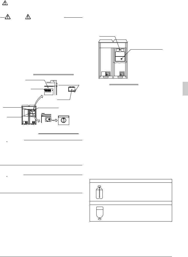
10. REFRIGERANT REPLENISHMENT
For refrigerant filling contractor
Use R410A for refrigerant replenishment.
The R410A refrigerant cylinder is painted with a pink belt.
|
Warning |
|
Electric Shock Warning |
|
|
|
|
•Securely close the control box lid before turning power on.
•Before turning power on, check through the inspection hole (on the left-hand side) of the control box lid that the RUN switch is set to OFF.
If the RUN switch is set to ON, the fan may rotate.
•Check the LED indicators on the PCB (A1P) of the outdoor unit through the inspection hole (on the right-hand side) of the control box lid after the outdoor unit is turned on (see the illustration).
(The compressor will not operate for approximately 2 minutes after the outdoor unit is turned on.
H2P blinks for the first five seconds when the power supply is turned on. If the equipment is normal, H2P will be turned off in five seconds. H2P lights for abnormality.)
Inspection hole (right-hand side) (upper right-hand side of control box)
Control box lid |
Lift up this tab and |
|
|
|
|
LED |
|
open the cover. |
(H1~8P) |
|
|
|
|
Inspection |
|
|
hole cover |
Inspection hole |
Inspection hole |
|
(left-hand side) |
(right-hand side) |
|
|
RUN switch |
|
Control box |
(factory set: OFF) |
|
REMOTE OFF ON |
||
|
||
|
Inspection hole (left-hand side) |
|
|
(upper left-hand side of control box) |


 WARNING
•Use protective gear (e.g., protective gloves and glasses) at the time of refrigerant filling.
•Pay attention to the rotation of the fan whenever the front panel is opened while working.
The fan can rotate continuously for a while after the outdoor unit stops operating.
[Refrigerant Replenishment Work]

 CAUTION
•Refer to the Operation Method of Shutoff Valves for the control method of the shutoff valves.
•Never replenish liquid refrigerant directly from a gas line. Liquid compression may cause the compressor to fail.
1.The refrigerant must be noted for this product. Calculate the amount of refrigerant replenishment according to the label for the calculation of the amount of refrigerant replenishment.
2.Take the following procedure for refrigerant replenishment. Refer to “8-1 Airtight Test/Vacuum Drying” for the connection of the refrigerant cylinder.
(1)Turn on the indoor unit and control panel. Do not turn on the outdoor unit.
(2)Replenish refrigerant from the service port of the shutoff valve on the liquid side.
(3)If the calculated amount of refrigerant cannot be filled, take the following steps to operate the system and continue refrigerant replenishment.
a.Open the gas shutoff valve all the way and adjust the opening of the liquid shutoff valve (*1).
b.[Warning/Electric Shock Warning]
Turn on the outdoor unit.
c.[Warning/Electric Shock Warning]
Turn on the RUN switch of the outdoor unit and replenish refrigerant while the outdoor unit is in operation.
d.Turn off the RUN switch of the outdoor unit after the specified amount of refrigerant is replenished.
e.[Caution]
Fully open the shutoff valves on the gas and liquid sides promptly. Otherwise, a piping explosion may result from liquid sealing.
Control box
Label of instructions on refrigerant replenishment
Label pasting position
*1 The cylinder’s internal pressure will drop when there is little refrigerant remaining in the cylinder, making it impossible to charge the unit, even if the liquid shutoff valve opening is adjusted. In this situation, replace the cylinder with one that has more refrigerant remaining.
Additionally, if the piping length is long, replenishing while the liquid shutoff valve is fully closed may lead to activation of the protection system, causing the unit to stop operation.
1.After the work is completed, apply a screw lock agent (for flare nuts) to the screws of the shutoff valves and service ports. Refer to the “Handling Precautions for Valve Cover” and “Handling Precautions for Service Port” in “6-5 Connecting the refrigerant piping” for the handling of the valve covers and service ports.
2.After the refrigerant replenishment is completed, fill out the item “total amount of refrigerant replenishment” on the label of instructions on refrigerant replenishment of the outdoor unit with the actual amount of refrigerant replenishment.
Refer to the illustration of the label pasting position for instructions on refrigerant replenishment (see the illustration on the above).
[Precautions for refrigerant cylinder]
At the time of refrigerant filling, check whether the siphon tube is provided. Then locate the cylinder so that the refrigerant will be filled in the state of liquid (see table below).
R410A is a mixed refrigerant, the composition of which may change and the normal operation of the system may not be possible if the refrigerant is filled in the state of gas.
Cylinder provided with siphon tube.
Stand the cylinder upright and fill the refrigerant. (There is a siphon tube inside, which makes it possible to replenish the refrigerant in the state of liquid without setting the cylinder upside down.)
Other cylinders
Stand the cylinder upside down and fill the refrigerant.
(Pay attention so that the cylinder will not topple down.)
English |
15 |

[Check through sight glass]
Full of liquid A little foam |
Foam always |
Sight glass |
flows. |
comes out. |
|
Sealing state |
Refrigerant insufficiency |
|

 CAUTION
•Fully open the shutoff valves on the liquid and gas sides after the refrigerant replenishment is finished.
The compressor will malfunction if the system is operated with the shutoff valves closed.
•Apply a screw lock agent to the screws of the valve cover mounting parts and service ports.
(Otherwise, dew condensation water will intrude and freeze inside and cause cap deformation or damage, which may result in refrigerant gas leakage or compressor malfunctions.)
11. TEST RUN
For test run operators
Do not operate the outdoor unit alone on a trial basis.
Test run procedure
Use the following procedure to perform a test run after installation work is complete for the entire system:
1.Fully open the shutoff valves on the gas and liquid sides of the outdoor unit.
2.Set the RUN switch of the outdoor switch to ON.
Note: Before turning power on, check that the piping cover and control box lid of the outdoor unit are closed.
3.Check the sealing condition of the outdoor unit through the sight glass. Make sure that the amount of refrigerant is sufficient.
4.Make sure that cold air blows from the indoor unit. Check that the internal temperature is dropping.
(Check that the temperature will drop and reach the set temperature in the internal unit. It will take approximately 40 minutes for the interior temperature of the internal unit to reach –20°C.) Check that the indoor unit (for refrigeration or freezing) goes into defrosting operation.
5.Turn power off with the RUN switch of the outdoor unit set to OFF. (Stopping unit operation by disconnecting the power supply directly is dangerous. When the unit is stopped in this manner, its power outage compensation function may cause it to resume operation as soon as the power supply is reactivated. Additionally, stopping the unit in this manner may cause the compressor to fail).
Error diagnosis
•If the system cannot operate normal at the time of test run (i.e., the H2P indicator is lit), check with malfunction code on the system with the pushbutton switches on the PCB of the outdoor unit, and take the following steps.
•Make checks on other malfunction codes and pushbutton switches by referring to the provided Technical Guide.
LED indication |
|
|
|
|
(BS3 switch pressed once) (BS2 switch pressed once) |
Installation failure |
Remedy |
||
H1P H2P H3P H4P H5P H6P H7P H1P H2P H3P H4P H5P H6P H7P |
|
|
|
|
or |
The shutoff valves |
Fully open the |
||
were left closed. |
shutoff valves. |
|||
|
||||
|
The passage of air |
Remove obstacles that |
||
|
is blocked. |
block the passage of air. |
||
|
Reverse-phase wiring |
Exchange two wires out of |
||
|
of power supply |
the three power supply wires. |
||
|
Voltage drop |
Make a voltage |
||
|
drop check. |
|
||
|
|
|
||
|
Electric leak |
See *1 below. |
||
|
Open L2 phase |
Verify power supply |
||
|
|
|||
|
|
wiring connections. |
||
Normal monitor (HAP) LED off. |
Open L1 phase |
|
|
|
|
Turned off |
Lit |
Flashes |
|
*1
Set the operating switch to the “OFF” position to reset the power supply and then return the switch to the “ON” position to restart the unit. If the problem persists, refer to the Service Manual.

 CAUTION
•Do not disconnect the power supply for 1 minute after setting the operating switch to “ON”.
Electric leak detection is performed for several seconds after the operating switch is set to “ON” and each compressor starts operating, so disconnecting the power supply during that time will result in a false detection.
For dealers
•After the test run is finished, check that the piping cover and front panel are mounted.
•At the time of delivery to the customer, use the Operation Manual and fully explain the handling of the equipment.
•For precautions at the time of delivery, refer to the provided Installation Manual for each unit as well.
16 |
English |
LRLEQ5AY1(E) |
LRLEQ12AY1(E) |
LRMEQ5AY1(E) |
LRMEQ12AY1(E) |
LRLEQ6AY1(E) |
LRLEQ15AY1(E) |
LRMEQ6AY1(E) |
LRMEQ15AY1(E) |
LRLEQ8AY1(E) |
LRLEQ20AY1(E) |
LRMEQ8AY1(E) |
LRMEQ20AY1(E) |
LRLEQ10AY1(E) |
|
LRMEQ10AY1(E) |
|
Luftgekühltes Installationsanleitung
Kältemittel-Kondensatorgerät
INHALTSVERZEICHNIS |
|
|
1. |
EINLEITUNG ........................................................................... |
1 |
|
1-1 Sicherheitshinweise .......................................................... |
1 |
|
1-2 Besonderer Hinweis zum Produkt..................................... |
2 |
|
1-3 Entsorgungsanforderungen .............................................. |
3 |
2. |
VOR DER INSTALLATION ...................................................... |
3 |
|
2-1 Standardzubehör .............................................................. |
3 |
|
2-2 Modellserie........................................................................ |
3 |
|
2-3 Beispiel der Systemkonfiguration...................................... |
3 |
|
2-4 Innengerät-Einschränkungen............................................ |
3 |
3. |
AUSWAHL DES STANDORTS................................................ |
3 |
4. |
HANDHABUNG DER EINHEIT................................................ |
5 |
5. |
AUFSTELLEN DES GERÄTES ............................................... |
5 |
6. |
KÄLTEMITTELLEITUNGEN .................................................... |
6 |
|
6-1 Wahl des Rohrleitungsmaterials ....................................... |
7 |
|
6-2 Schutz gegen Verunreinigung bei der |
|
|
Installation der Rohre........................................................ |
8 |
|
6-3 Leitungsverbindung........................................................... |
8 |
|
6-4 Installation eines Trockners .............................................. |
8 |
|
6-5 Anschluß der Kältemittelleitungen .................................... |
8 |
7. |
BAUSEITIGE VERDRAHTUNG............................................. |
11 |
|
7-1 Beispiel der Verkabelung des ganzen Systems.............. |
11 |
|
7-2 Verfahren für eingehende Verkabelung .......................... |
12 |
|
7-3 Verfahren für Stromversorgungsverkabelung ................. |
12 |
|
7-4 Verkabelungsverfahren für das Geräteinnere................. |
14 |
8. |
INSPEKTION UND ROHRISOLIERUNG............................... |
15 |
|
8-1 Luftdichtheitstest/Vakuumtrocknung ............................... |
15 |
|
8-2 Wärmeisolierung ............................................................. |
15 |
|
8-3 Überprüfen des gerätes und der |
|
|
Installationsbedingungen ................................................ |
16 |
9. |
KONTROLLEN NACH ABSCHLUSS DER ARBEIT .............. |
16 |
10. |
KÄLTEMITTEL-NACHFÜLLUNG........................................... |
16 |
11. |
PROBELAUF ......................................................................... |
17 |
1.EINLEITUNG
•Dieses Dokument ist eine Installationsanleitung für das luftgekühlte Kältemittel-Kondensatorgerät von Daikin. Bitte lesen Sie diese Anleitung vor der Installation des Gerätes sorgfältig durch, und befolgen Sie die darin enthaltenen Anweisungen.
Führen Sie nach der Installation einen Probelauf durch, um sicherzustellen, dass das Gerät einwandfrei funktioniert, und erklären Sie dann dem Kunden anhand der Bedienungsanleitung, wie das Gerät zu bedienen und zu pflegen ist.
•Raten Sie abschließend dem Kunden, diese Anleitung zusammen mit der Bedienungsanleitung an einem sicheren Ort aufzubewahren.
•Diese Anleitung beschreibt nicht die Installation des Innengeräts. Siehe dazu die Installationsanleitung des Innengeräts.
1-1 Sicherheitshinweise
Bitte lesen Sie diese “Sicherheitshinweise” sorgfältig durch, bevor Sie das Kondensatorgerät installieren, um korrekte Installation zu gewährleisten.
Führen Sie nach Abschluss der Installation einen Probelauf durch, um etwaige Fehler festzustellen, und erklären Sie dem Kunden anhand der Bedienungsanleitung, wie das Kondensatorgerät zu bedienen und zu pflegen ist. Bitten Sie den Kunden, die Installationsanleitung zusammen mit der Bedienungsanleitung für späteres Nachschlagen aufzubewahren.
Bedeutung der Hinweise WARNUNG und ACHTUNG
WARNUNG ...Eine Missachtung dieser Anweisungen kann zu Körperverletzungen oder Tod führen.
ACHTUNG ....Eine Missachtung dieser Anweisungen kann zu Sachbeschädigung oder Körperverletzungen führen, die je nach den Umständen ernsthaft sein können.


 WARNUNG
•Beauftragen Sie Ihren Händler oder qualifiziertes Personal mit der Installation der Anlage.
Versuchen Sie nicht, das Kondensatorgerät selbst zu installieren. Eine unsachgemäße Installation kann zu Wasserlecks, elektrischen Schlägen oder Brand führen.
•Installieren Sie das Kondensatorgerät gemäß den Anweisungen in dieser Installationsanleitung.
Eine unsachgemäße Installation kann zu Wasserlecks, elektrischen Schlägen oder Brand führen.
•Treffen Sie bei der Installation des Geräts in einem kleinen Raum Vorkehrungen, so dass die Menge austretenden Kühlmittels bei auftretenden Lecks die zulässigen Grenzwerte nicht überschreitet.
Wenden Sie sich für weitere Informationen an die Kaufstelle. Eine übermäßige Kältemittelmenge in einem geschlossenen Raum kann zu Sauerstoffmangel führen.
•Verwenden Sie nur vorgeschriebenes Zubehör und Teile für die Installationsarbeiten.
Bei Verwendung ungeeigneter Teile besteht die Gefahr, dass das Gerät herunterfällt oder ein Wasserleck, elektrischer Schlag oder Brand verursacht wird.
•Installieren Sie das Kondensatorgerät auf einem Fundament, das stark genug für das Gewicht des Geräts ist.
Ein Fundament von unzureichender Tragfähigkeit kann zu Herunterfallen und Unfällen mit Verletzungen führen.
•Führen sie die vorgeschriebenen Installationsarbeiten nach Berücksichtigung starker Winde, Wirbelstürme oder Erdbeben aus.
Anderenfalls besteht die Gefahr, dass das Gerät herunterfällt und Unfälle verursacht.
•Sicherstellen, daß ein getrennter Betriebsstromkreis für diese Anlage vorhanden ist und daß elektrische Arbeiten nur von qualifizierten Fachleuten unter Beachtung aller örtlich gültigen Gesetze und Vorschriften und dieser Anleitung ausgeführt werden.
Eine unzureichende oder falsch ausgeführte Betriebsstromversorgung kann zu elektrischen Schlägen oder Bränden führen.
•Vergewissern Sie sich, dass die gesamte Verkabelung sicher befestigt ist, die vorgeschriebenen Kabeltypen verwendet werden und die Klemmenanschlüsse oder Kabel keiner Belastung ausgesetzt sind.
Falsche Anschlüsse oder Befestigung der Kabel können zu abnormaler Wärmebildung oder einem Brand führen.
•Bei der Verkabelung der Stromversorgung und der Verbindung der Übertragungskabel sind die Kabel so zu verlegen, dass der Schaltkastendeckel sicher befestigt werden kann.
Falsche Anbringung des Schaltkastendeckels kann zu elektrischen Schlägen, Brand oder Überhitzen der Klemmen führen.
•Falls Kältemittelgas während der Installation entweicht, ist der Bereich sofort zu belüften.
Giftiges Gas kann entstehen, falls das Kältemittelgas mit Feuer in Berührung kommt.
•Überprüfen Sie die Anlage nach der Installation auf Kältemittelgaslecks.
Giftiges Gas kann erzeugt werden, falls Kältemittelgas in den Raum entweicht und mit einer Feuerquelle wie z. B. einem Heizkörper, Ofen oder Herd in Berührung kommt.
•Schalten Sie das Gerät unbedingt aus, bevor Sie Elektroteile berühren.
•Vermeiden Sie direkte Berührung von Kältemittel, das aus Kältemittelleitungen oder anderen Bereichen ausgelaufen ist, da Erfrierungsgefahr besteht.
•Lassen Sie nicht zu, dass Kinder auf das Außengerät klettern, und stellen Sie auch keine Gegenstände auf das Gerät.
Es kann zu Verletzungen kommen, falls das Gerät sich lockert und herunterfällt.
Deutsch |
1 |

•Das Kondensatorgerät muss unbedingt geerdet werden. Erden Sie das Gerät nicht an einer Gasoder Wasserleitung, einem Blitzableiter oder der Erdleitung eines Telefons. Falsche Erdung kann zu elektrischen Schlägen oder Brand führen.
Ein starker Stromstoß von einem Blitzschlag oder anderen Quellen kann Beschädigung des Kondensatorgeräts verursachen.
•Immer einen Leckstrom-Unterbrecher installieren.
Wenn keine Erdschluss-Sicherung installiert ist, besteht die Gefahr von elektrischen Schlägen oder Feuer.

 ACHTUNG
•Installieren Sie die Ablaufleitungen nach den Anweisungen in dieser Installationsanleitung, um einwandfreies Ablaufen zu gewährleisten, und isolieren Sie die Leitungen, um Kondensation zu verhüten.
Falsche Verlegung der Ablaufleitungen kann zu Wasserlecks und Sachschäden im Innenraum führen.
•Installieren Sie Innenund Außengerät sowie die Stromversorgungsund Verbindungskabel in mindestens 1 m Abstand von Fernsehgeräten oder Radios, um Bildstörungen oder Rauschen zu vermeiden.
(Je nach der einfallenden Signalstärke ist ein Abstand von
1m eventuell nicht ausreichend, um Rauschen zu vermeiden.)
•Installieren Sie das Kondensatorgerät nicht an folgenden Orten:
1.Orte mit hoher Konzentration von Mineralölnebel oder Dampf (z. B. in einer Küche).
Kunststoffteile können sich zersetzen, was zu Herunterfallen von Teilen oder Wasserlecks führen kann.
2.Orte, an denen korrosive Gase, wie z. B. Schwefelsäuregas, erzeugt werden.
Korrosion von Kupferleitungen oder gelöteten Teilen kann zu Kältemittellecks führen.
3.Orte in der Nähe von Maschinen, die elektromagnetische Strahlung abgeben.
Elektromagnetische Strahlung kann den Betrieb des Steuersystems stören und eine Funktionsstörung des Gerätes verursachen.
4.Orte, an denen brennbare Gase ausströmen können, an denen Kohlenstofffasern oder entzündliche Staubpartikel in der Luft vorhanden sind, oder an denen leichtflüchtige Zündstoffe, wie Lackverdünner oder Benzin, gehandhabt werden. Der Betrieb des Gerätes unter solchen Bedingungen kann zu einem Brand führen.
5.Fahrzeuge, Schiffe oder andere Orte, die Vibrationen erzeugen oder eine Verlagerung des Kondensatorgeräts verursachen.
Es kann zu einer Funktionsstörung des Kondensatorgeräts oder zu Unfällen mit Sauerstoffmangel durch Kältemittellecks kommen.
6.Orte mit übermäßigen Spannungsschwankungen.
Es kann zu einer Funktionsstörung des Kondensatorgeräts kommen.
7.Orte, an denen sich Laub ansammelt oder Unkraut wuchert.
8.Orte, die Kleintieren Unterschlupf gewähren.
Kleintiere, die mit Elektroteilen in Berührung kommen, können Funktionsstörungen, Rauch oder Entflammung verursachen.
•Das Kondensatorgerät ist nicht für den Einsatz in einer potentiell explosiven Atmosphäre vorgesehen.
1-2 Besonderer Hinweis zum Produkt
Dieses Kondensatorgerät fällt unter die Kategorie “Geräte, die der Öffentlichkeit nicht zugänglich sind”.
[KLASSIFIZIERUNG]
Dieses Kondensatorgerät fällt unter die Kategorie “Geräte, die der Öffentlichkeit nicht zugänglich sind”.
[EMV-EIGENSCHAFTEN]
Dieses System ist ein Produkt der Klasse A. In einer Wohnumgebung kann dieses Produkt Funkstörungen verursachen, so dass der Benutzer angehalten ist, angemessene Gegenmaßnahmen zu ergreifen.
[KÄLTEMITTEL]
Dieses System verwendet das Kältemittel R410A.

 ACHTUNG
Dieses Gerät ist bereits mit einer bestimmten Menge R410A gefüllt. Öffnen Sie keinesfalls das Flüssigkeitsund Gasabsperrventil bis zu dem unter “9. KONTROLLEN NACH ABSCHLUSS DER ARBEIT” angegebenen Schritt.
•Das Kältemittel R410A erfordert strenge Vorsichtsmaßnahmen, um das System sauber, trocken und dicht zu halten.
Lesen Sie das Kapitel “KÄLTEMITTELLEITUNGEN” aufmerksam durch, und halten Sie sich genau an diese Verfahren.
A.Sauber und trocken
Das Eindringen von Fremdstoffen (einschließlich Mineralölen, wie z. B. SUNISO-Öl, oder Feuchtigkeit) muss verhindert werden.
B.Dicht
Achten Sie bei der Installation darauf, das System dicht zu halten.
R410A enthält kein Chlor, zerstört nicht die Ozonschicht und verringert nicht den Schutz der Erde vor schädlicher Ultraviolettstrahlung.
R410A kann den Treibhauseffekt geringfügig verstärken, falls es freigelassen wird.
•Da R410A ein gemischtes Kältemittel ist, muss das erforderliche zusätzliche Kältemittel in seinem flüssigen Zustand eingefüllt werden. Wird das Kältemittel in gasförmigem Zustand eingefüllt, verändert sich seine Zusammensetzung, und das System funktioniert nicht einwandfrei.
•Führen Sie unbedingt eine Kältemittel-Nachfüllung durch. Nehmen Sie auf “9. KONTROLLEN NACH ABSCHLUSS DER ARBEIT” und den Aufkleber mit Anweisungen zum Nachfüllen von Kältemittel auf der Abdeckung des Steuerkastens Bezug.
Wichtige Informationen hinsichtlich des verwendeten Kältemittels
Dieses Produkt enthält fluorierte Treibhausgase, die durch das Kyoto-Protokoll abgedeckt werden. Lassen Sie Gase nicht in die Atmosphäre ab.
Kältemitteltyp:R410A
GWP(1) Wert: : 2090
(1) GWP = Treibhauspotential
Bitte füllen Sie am Kältemittelbefülletikett, das im Lieferumfang des Gerätes enthalten ist, mit abriebfester Tinte wie folgt aus:
Q die werkseitige Kältemittelbefüllung des Produktes,
Q die am Montageort befüllte zusätzliche Kältemittelmenge und
Q +
+  die gesamte Kältemittelbefüllung
Das ausgefüllte Etikett muss in der Nähe der Kältemittel-Einfüllöff- nung angehängt werden (z.B. auf der Innenseite der Wartungsblende).
|
|
|
|
|
|
|
|
|
4 |
1 |
werkseitige Kältemittel- |
||||||
|
|
|
|
|
|
|
|
|
|
|
|
|
|
|
|||
|
|
|
|
|
|
|
|
|
|
|
|
|
|
|
|
||
|
|
|
|
|
|
|
|
|
|
|
|
|
|
|
|
|
befüllung des Produktes: |
|
|
|
|
|
|
|
|
|
|
|
|
|
1 |
|
siehe Typenschild der |
||
|
|
|
|
|
|
|
|
|
|
|
|
|
|
||||
|
|
|
|
|
|
|
|
|
|
|
|
|
|||||
|
|
|
|
|
|
|
|
|
|
|
|
|
|
|
2 |
|
Einheit |
|
|
|
|
|
|
|
|
|
|
|
|
|
|
|
|
||
|
|
|
|
|
|
|
|
|
|
|
|
|
2 |
zusätzliche am Montageort |
|||
|
|
|
|
|
|
|
|
|
|
|
|
|
|||||
|
|
|
|
|
|
|
|
|
|
|
|
|
|
|
|
|
befüllte Kältemittelmenge |
|
|
|
|
|
|
|
|
|
|
|
|
|
|
|
3 |
3 |
gesamte |
|
|
|
|
|
|
|
|
|
|
|
|
|
|
|
|
|
Kältemittelbefüllung |
|
6 |
5 |
|
|
|
|
|
|
|
|
|
4 |
Enthält fluorierte |
||||
|
|
|
|
|
|
|
|
|
|
|
|
|
|
|
|
||
|
|
|
|
|
|
|
|
|
|
|
|
|
|
|
|
|
Treibhausgase, die durch |
|
|
|
|
|
|
|
|
|
|
|
|
|
|
|
|
|
das Kyoto-Protokoll |
|
|
|
|
|
|
|
|
|
|
|
|
|
|
|
|
|
abgedeckt werden |
|
|
|
|
|
|
|
|
|
|
|
|
|
|
|
|
5 |
Außeneinheit |
|
|
|
|
|
|
|
|
|
|
|
|
|
|
|
|
6 |
Kältemittelzylinder und |
|
|
|
|
|
|
|
|
|
|
|
|
|
|
|
|
|
Sammelleitung für die |
|
|
|
|
|
|
|
|
|
|
|
|
|
|
|
|
|
Befüllung |
[GENEHMIGUNGSDRUCK]
Da der Genehmigungsdruck 3,8 MPa oder 38 bar (für R407CGeräte: 3,3 MPa oder 33 bar) beträgt, sollte die Wanddicke der Rohre sorgfältig gemäß den örtlichen und nationalen Bestimmungen ausgewählt werden.
2 |
Deutsch |
1-3 Entsorgungsanforderungen
Die Demontage des Geräts sowie die Behandlung von Kältemittel, Öl und anderen Teilen müssen gemäß der relevanten örtlichen und nationalen Gesetzgebung erfolgen.
2.VOR DER INSTALLATION

 ACHTUNG
•Nehmen Sie bei der Installation des Innengeräts dessen Installationsanleitung zur Hand.
•Sonderzubehörteile sind für die Installation des Produkts erforderlich. Siehe die Informationen über Sonderzubehör.
2-1 Standardzubehör
Die folgenden Zubehörteile werden mitgeliefert. Abbildung zeigt den Aufbewahrungsort der Zubehörteile.
Hinweis

Werfen Sie keines der Zubehörteile weg, bevor die Installation abgeschlossen ist.
Beze- |
Klemme (1) |
Klemme (2) |
Klemme (3) |
Rohr für |
Rohr für |
ichnung |
Gasseite (1) |
Gasseite (2) |
|||
|
|
|
|
|
|
Menge |
11 Stck. |
1 Stck. |
1 Stck. |
1 Stck. |
1 Stck. |
Form
Bezeich- |
Rohr für Flüs- |
Rohr für Flüs- |
Sonstiges |
|
nung |
sigkeitsseite (1) |
sigkeitsseite (2) |
||
|
||||
|
|
|
|
|
Menge |
1 Stck. |
1 Stck. |
1 Stück zu jedem |
|
Artikel |
||||
|
|
|
• Betriebsanweisung
• Installationsanleitung
• ÜbereinstimmungForm serklärung (PED)
• Aufkleber “ZUSÄTZLICHE KÄLTEMITTELFÜLLUNG”
2-2 Modellserie
MT (Mittlere Temperatur) |
LRMEQ5~20AY1(E) |
|
|
LT (Niedrige Temperatur) |
LRLEQ5~20AY1(E) |
|
|
2-3 Beispiel der Systemkonfiguration
Beze- |
|
Innenaggregat |
|
|
Außenaggregat |
MT (Mittlere Temperatur) |
|||
ichnung |
||||
|
Gerätekühler |
Vitrine |
||
|
|
|||
Form |
|
|
|
|
Beze- |
Innenaggregat |
Steuertafel |
|
|
|
||||||||
|
|
|
|
|
|
|
|
|
|||||
LT (Niedrige Temperatur) |
Warntafel |
||||||||||||
ichnung |
(Entfrosten) |
||||||||||||
|
|
|
|
|
|
|
|
|
|||||
|
Gerätekühler |
|
Vitrine |
|
|
|
|
|
|
||||
|
|
|
|
|
|
|
|
|
|
|
|
|
|
Form |
|
|
|
|
|
|
|
|
|
|
|
|
|
|
|
|
|
|
|
|
|
|
|
|
|
||
|
|
|
|
|
|
|
|
|
|
|
|
||
|
|
|
|
|
|
|
|
|
|
|
|
||
|
|
|
|
|
|
|
|
|
|
|
|
|
|
|
|
|
|
|
|
|
|
|
|
|
|
|
|
|
|
|
|
|
|
|
|
|
|
|
|
|
|
|
|
|
|
|
|
|
|
|
|
|
|
|
|
|
|
|
|
|
|
|
|
|
|
|
|
|
|
[Typ 5A, 6A] [Typ 8A, 10A, 12A]
1, 2, 3 |
1, 2, 3 |
|
 4
4
4
[Typ 15A, 20A]
1, 2, 3
 4
4
1Betriebsanweisung
2Installationsanleitung
3Klemmen
4Mitgelieferte Rohre (Am Bodenrahmen installiert)
2-4 Innengerät-Einschränkungen
•Installieren Sie ein mechanisches thermostatisches R410AExpansionsventil an jedem Innengerät.
•Isolieren Sie den Fühlerblock des mechanischen thermostatischen Expansionsventils.
•Installieren Sie ein R410A-Magnetventil (max. Betriebsdifferenzdruck von 3,5 MPa [35 bar] oder mehr) auf der Primärseite des oben beschriebenen mechanischen thermostatischen Expansionsventils für jedes Innengerät.
•Installieren Sie einen Filter auf der Primärseite des oben beschriebenen Magnetventils für jedes Innengerät. Ermitteln Sie den Filterfeinheitswert anhand der vom verwendeten Magnetventil und mechanischen thermostatischen Expansionsventil vorgeschriebenen Größe.
•Verlegen Sie die Leitung zum Innengerät-Wärmetauscher, so dass das Kältemittel von oben nach unten fließt.
•Wenn mehrere Innengeräte installiert werden, müssen sie auf gleicher Höhe installiert werden.
•Verwenden Sie entweder Aus-Zyklus-Entfrostung oder Elektro- heizungs-Entfrostung als Entfrostungstyp. Modelle mit HeißgasEntfrostung können nicht verwendet werden.
3.AUSWAHL DES STANDORTS
Wählen Sie einen Installationsort, der die folgenden Bedingungen erfüllt.
Holen Sie sich die Erlaubnis des Kunden.
1.Es besteht keine Brandgefahr aufgrund von austretendem Gas.
2.Wählen Sie den Standort für die Einheit so aus, daß weder die ausgeblasene Luft noch das Betriebsgeräusch der Einheit zu Belästigungen führt.
3.Das Fundament ist stark genug, um das Gewicht der Einheit zu tragen, und der Boden ist flach, so daß Vibrationen und Lärm vermieden werden.
4.Die Leitungslänge zwischen Außenund Inneneinheit darf die zulässige Leitungslänge nicht überschreiten.
(Siehe “6. KÄLTEMITTELLEITUNGEN”)
Deutsch |
3 |

5.Orte, an denen die Ansaugund Auslassöffnungen des Gerätes normalerweise keinem Wind ausgesetzt sind.
Wind, der direkt in die Ansaugoder Auslassöffnungen weht, beeinträchtigt den Betrieb des Gerätes.
Installieren Sie nötigenfalls einen Windschutz, um den Wind abzuweisen.
6.Es muss ausreichend Platz für die Wartung um das Gerät vorhanden sein, und der minimale Platz für den Lufteinlass und Luftauslass muss vorhanden sein.
(Siehe die “Installationsort-Beispiele” für die minimalen Platzanforderungen.)
Installationsort-Beispiele
•Die in der nachstehenden Abbildung gezeigte InstallationsplatzAnforderung dient als Referenz für Kühlbetrieb bei einer Außentemperatur von 32°C.
Falls die Außentemperatur 32°C überschreitet oder die Wärmebelastung die Maximalkapazität in allen Außengeräten überschreitet, ist der in der nachstehenden Abbildung gezeigte Platz für den Lufteinlass weiter zu vergrößern.
•Die Geräte sind so zu installieren, dass für den jeweiligen Installationsort das am besten geeignete Muster unter denen in der nachstehenden Abbildung gezeigten verwendet wird, wobei Personenverkehr und Wind zu berücksichtigen sind.
•Überschreitet die Zahl der installierten Geräte die Zahl des in der nachstehenden Abbildung gezeigten Musters, sind die Geräte so zu installieren, dass keine Kurzschlüsse entstehen.
•Was den Platz vor dem Gerät betrifft, so ist der für die lokalen Kältemittelleitungen notwendige Platz bei der Installation der Geräte zu berücksichtigen.
•Falls die Arbeitsbedingungen in der nachstehenden Abbildung nicht zutreffen, wenden Sie sich an Ihren Händler oder direkt an Daikin.
< Bei Installation als Einzelgerät > |
<Bei Serieninstallation > |
|
||||||||
(Muster 1) HINWEIS) |
<![if ! IE]> <![endif]>Wartungsplatz auf der Ansaugseite |
(Muster 1) HINWEIS) |
<![if ! IE]> <![endif]>Wartungsplatz auf der Ansaugseite |
|||||||
|
|
|
|
|
|
|
|
|
||
|
|
<![if ! IE]> <![endif]>≥300 |
|
|
|
|
<![if ! IE]> <![endif]>≥300 |
|
||
|
|
|
|
|
|
|||||
|
|
|
|
|
|
|||||
|
|
|
|
|
|
|
|
|
||
|
|
|
|
|
|
|
|
|
<![if ! IE]> <![endif]>500≥ |
<![if ! IE]> <![endif]>Wartungsplatzauf Vorderseiteder |
≥10 |
||
≥10 |
|
|
|
|
|
|
|
≥10 |
|
|
|
||
|
|
|
|
|
|
|
|
|
|||||
|
|
|
|
|
|
|
|
|
|
|
|
|
≥20 |
|
Vorderseite |
|
|
|
|
|
|||||||
|
|
|
|
|
|
|
|||||||
|
|
|
|
|
|
|
|
|
|
|
|
|
|
(Muster 2) HINWEIS) |
<![if ! IE]> <![endif]>≥100 |
<![if ! IE]> <![endif]>Wartungsplatz auf |
<![if ! IE]> <![endif]>der Ansaugseite |
|
|
||||||||||
|
|
|
|
|
|
|
|
|
|
≥50 |
|
||||
≥50 |
|
|
|
|
|
|
≥50 |
<![if ! IE]> <![endif]>500≥ |
|
<![if ! IE]> <![endif]>Wartungsplatzauf |
<![if ! IE]> <![endif]>Vorderseiteder |
|
|||
|
|
|
|
|
|
|
|
||||||||
|
|
|
|
|
|
|
|
|
|
|
|
|
|
≥100 |
|
|
Vorderseite |
|
|
|
|
|
|
||||||||
|
|
|
|
|
|
|
|
||||||||
|
|
|
|
|
|
|
|
|
|
|
|
|
|
|
|
(Muster 3)
|
≥10 |
<![if ! IE]> <![endif]>Wartungsplatzauf Vorderseiteder |
|
<![if ! IE]> <![endif]>500≥ |
|
|
≥20 |
|
Vorderseite |
|
|
(Muster 2) HINWEIS) |
|
<![if ! IE]> <![endif]>Wartungsplatz auf |
<![if ! IE]> <![endif]>der Ansaugseite |
|
<![if ! IE]> <![endif]>≥100 |
||
|
≥50 |
<![if ! IE]> <![endif]>Wartungsplatzauf |
<![if ! IE]> <![endif]>Vorderseiteder |
|
<![if ! IE]> <![endif]>500≥ |
||
|
≥100 |
|
|
Vorderseite |
|
|
|
Keine Begrenzung
der Wandhöhe
(Muster 3)
|
<![if ! IE]> <![endif]>300≥ |
Keine Begrenzung |
<![if ! IE]> <![endif]>300≥ |
|
|
|
|
|
|
der Wandhöhe |
|
≥200 |
|
≥200 |
|
|
≥400 |
≥400 |
|
|
|
||
|
Vorderseite |
Vorderseite |
|
|
|
|
|
HINWEIS) Für Muster 1 und 2
•Wandhöhe auf der Vorderseite – nicht höher als 1500 mm.
•Wandhöhe auf der Ansaugseite – nicht höher als 500 mm.
•Wandhöhe für die Seiten – unbegrenzt.
•Falls die Höhe die obigen Werte überschreitet, die in der nachstehenden Abbildung gezeigten Maße h1 und h2 berechnen, und h1/2 zu dem Wartungsplatz auf der Vorderseite, und h2/2 zum dem Wartungsplatz auf der Ansaugseite hinzufügen.
|
<![if ! IE]> <![endif]>h1 |
|
|
|
|
| <![if ! IE]> <![endif]>A |
<![if ! IE]> <![endif]>1500 |
<![if ! IE]> <![endif]>Vorderseite |
<![if ! IE]> <![endif]>Ansaugseite |
<![if ! IE]> <![endif]>500 h2 |
<![if ! IE]> <![endif]>B |
Wartungsplatz
Wartungsplatz
h1 = A (Tatsächliche Höhe) – 1500
h2 = B (Tatsächliche Höhe) – 500 X = 500 + h1/2 oder mehr
Y = 300 + h2/2 oder mehr (Y = 100 + h2/2 oder mehr)
[Die Werte in Klammern gelten für Muster 2]

 ACHTUNG
Abzweigschalter, |
|
|
|
|
Steuertafel |
Überlastschalter |
|
|
|
|
Warntafel |
(Fehlerstrom-Schutzschalter) |
|
|
|
|
Abzweigschalter, |
|
|
|
|
|
Überlastschalter |
|
|
|
|
|
(Fehlerstrom- |
|
|
|
|
|
Schutzschalter) |
|
≥ |
1500 |
|
1500 |
|
|
|
|
|
||
|
|
|
≥ |
|
≥1500 |
≥ |
|
|
|
|
|
|
|
|
|
≥1500 |
|
1500 |
|
|
|
|
|
Vitrine |
|
|
|
|
(mm) |
1. Ein Inverter-Kondensatorgerät kann von Mittelwellenfunk erzeugte Störgeräusche verursachen. Überprüfen Sie den Installationsort des Haupt-Kondensatorgeräts und der Elektrokabel, und halten Sie ausreichenden Abstand zu Stereogeräten, Personal Computern usw. ein.
Besonders an Orten mit schwachem Empfang ist darauf zu achten, dass ein Abstand von mindestens 3 m für die Innengeräte-Fernbedienungen vorhanden ist, dass die Stromversorgungskabel und die Übertragungskabel in Schutzrohren verlegt und die Schutzrohre geerdet werden.
2. Bei Installation an Orten mit starkem Schneefall sind die folgenden Schneeschutzmaßnahmen zu treffen.
• Sicherstellen, dass der Sockel hoch genug ist, damit die Einlassöffnungen nicht durch Schnee blockiert werden.
• Montieren Sie eine Schneeschutzhaube (Sonderzubehör)
• Den hinteren Einlassgrill abnehmen, um die Ansammlung von Schnee auf den Lamellen zu verhüten.
3. Falls Kondensat je nach den Bodenverhältnissen auf ein tieferes Stockwerk (oder Gehweg) tropft, sind Maßnahmen wie die Installation eines zentralen Abflusswannensatzes (getrennt erhältlich) zu treffen.
4. Das Kältemittel R410A ist ungiftig, unentflammbar und sicher. Sollte das Kältemittel jedoch austreten, kann seine Konzentration je nach Raumgröße die zulässigen Grenzwerte überschreiten. Aus diesem Grund kann es notwendig sein, Maßnahmen gegen Undichtigkeit zu treffen.
Siehe “Konstruktionsdaten” für Details.
|
|
|
|
|
|
4 |
Deutsch |
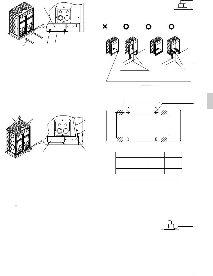
4.HANDHABUNG DER EINHEIT
1.Legen Sie die Transportroute fest.
2.Wenn ein Gabelstapler verwendet werden soll, sind dessen Gabeln in die großen Öffnungen auf der Unterseite der Einheit einzuführen.
1
•Die Höhe des Sockels muss mindestens 150 mm über dem Fußboden betragen.
•Das Gerät mit den Ankerschrauben an seinem Sockel befestigen. (Je vier im Handel erhältliche M12-Ankerschrauben, Muttern und Unterlegscheiben verwenden.)
•Die Ankerschrauben sollten 20 mm weit eingeführt werden.
<![if ! IE]><![endif]>20
4
2 |
3 |
1Öffnung (groß)
2Gabel
3Befestigungsschrauben der Transportklammer
4Transportklammer (gelb)
Falls das Gerät aufgehängt werden muss, ist eine Stoffschlinge zu verwenden, um Beschädigung des Gerätes zu vermeiden. Punkte nach dem in der nachstehenden Abbildung gezeigten Verfahren auf.
• Verwenden Sie eine Schlinge, die stark genug ist, um das Gewicht des Gerätes zu tragen.
• Verwenden Sie 2 Gurte von mindestens 8 m Länge.
• Schützen Sie die Stellen, an denen das Gehäuse mit der Schlinge in Berührung kommt, durch zusätzliche Tücher, um Beschädigung zu vermeiden.
• Achten Sie beim Hochziehen des Gerätes darauf, dass es an seinem Schwerpunkt angehoben wird.
1 2
4
5
6
3
1Gurtschlinge
2Abdecktuch
3Öffnung (groß)
Für Größe 5A oder 6A verwendet
4Gurtschlinge
5Abdecktuch
6Öffnung (klein)
Für Größe 8A, 10A, 12A, 15A, oder 20A verwendet
3.Entfernen Sie nach der Installation die an den großen Öffnungen angebrachten Transportklammern (gelb).
Hinweis

Ein Fülltuch an einer Gabel anbringen, um zu verhüten, dass sich der Belag des unteren Rahmens ablöst und Rost auftritt, wenn das mit Rostschutzbehandlung versehene Gerät mit einem Gabelstapler geliefert wird.
5.AUFSTELLEN DES GERÄTES
•Überzeugen Sie sich davon, dass das Gerät in der Waage auf einem ausreichend starken Sockel installiert wurde, um Vibrationen und Geräuschentwicklung zu vermeiden.
•Die Basis sollte größer als die Breite der Füße der Einheit (66 mm) sein und die Einheit tragen.
Wenn eine Gummimatte angebracht werden soll, ist diese auf der ganzen Fläche des Sockels anzubringen.
Eckenloch- |
Unabhängiges . |
Trägerfundament |
Trägerfundament |
|
Fundament |
Fundament |
(horizontal) |
(vertikal) |
|
|
≥100 |
|
|
≥100 |
|
|
|
|
|
|
|
|
|
Für Größe |
|
Für Größe 5A |
|
5A oder 6A |
|
≥100 |
oder 6A nicht |
≥100 |
nicht |
|
100 |
erforderlich |
|
≥100 |
erforderlich |
≥ |
|
|
||
Mitte des Produkts |
|
Mitte des Produkts |
||
Das Eckenloch-Fundament, bei dem das Gerät mit den Löchern an den vier Ecken gesichert wird, ist für die Größen 8A, 10A, 12A, 15A, 20A nicht verfügbar. Das Eckenloch-Fundament ist jedoch für die Größen 5A und 6A verfügbar.
|
Trägersockel |
|
|
|
|
|
|
Ankerschraubenpunkt |
|
|
A |
|
(4-15 × 22,5) |
|
|
B |
|
|
|
| <![if ! IE]> <![endif]>765 (Tiefe des Produkts) |
<![if ! IE]> <![endif]>729 |
|
<![if ! IE]> <![endif]>631 |
<![if ! IE]> <![endif]>(Innenabmessung des Sockels) 765 oder mehr (Außenabmessung des Sockels) |
|
|
|
|
(Einheit:mm) |
|
Modell |
A |
|
B |
|
Typ 5A · 6A |
635 |
|
497 |
|
Typ 8A · 10A · 12A |
930 |
|
792 |
|
Typ 15A · 20A |
1240 |
|
1102 |
Basisbreite und Basisschraubenpositionen
Hinweis

•Bei Dachmontage ist sicherzustellen, dass der Dachboden stabil genug ist, und alle Arbeiten sind wasserfest zu machen.
•Sicherstellen, dass einwandfreier Abfluss im Bereich um die Maschine gewährleistet ist, indem Abflussrinnen um das Fundament eingerichtet werden.
Das Außengerät gibt während des Betriebs manchmal Abwasser ab.
• Wenn das Kondensatorgerät salzlaugenbeständig oder stark salzlaugenbeständig ist, verwenden Sie Muttern mit Kunstharzscheiben zur Befestigung des Produkts an den Ankerschrauben (siehe die Abbildung auf der rechten Seite).
Der Rostschutzeffekt der Muttern geht verloren, falls sich die Beschichtung an den Anzugsteilen der Muttern lösen.
Deutsch |
5 |

6.KÄLTEMITTELLEITUNGEN
An Rohrleitungsinstallateure
•Das Absperrventil darf keinesfalls vor den unter “7. BAUSEITIGE VERDRAHTUNG” und “8-3. Überprüfen des gerätes und der Installationsbedingungen” beschriebenen Schritten der Rohrleitungen geöffnet werden.
•Verwenden Sie kein Flussmittel beim Hartlöten und Verbinden der Kältemittelleitungen. Verwenden Sie zum Hartlöten eine Hartlotlegierung auf Kupfer-Phosphor-Basis (BCuP-2), die kein Flussmittel erfordert. Flussmittel auf Chlorbasis verursacht Korrosion der Leitungen. Falls darüber hinaus Fluor enthalten ist, hat das Flussmittel einen negativen Einfluss auf die Kältemittelleitung, wie z. B. Verschlechterung des Kältemittel-Maschinenöls.

 ACHTUNG
•Alle Vor-Ort-Rohrleitungen müssen von einem lizenzierten Kältetechniker installiert werden und den relevanten örtlichen und nationalen Vorschriften entsprechen.
[Vorsichtsmaßnahmen für die Wiederverwendung von vorhandenen Kältemittelleitungen / Wärmetauschern]
Bei Wiederverwendung von Kältemittelleitungen / Wärmetauschern die folgenden Punkte beachten.
Bei Mängeln kann es zu einer Funktionsstörung kommen.
•Benutzen Sie die vorhandenen Rohrleitungen nicht in den folgenden Fällen. Verwenden Sie statt dessen neue Rohrleitungen.
•Die Größe der Rohrleitungen ist unterschiedlich.
•Die Festigkeit der Rohrleitungen ist unzureichend.
•Der Kompressor des vorher verwendeten Kondensatorgeräts hat eine Funktionsstörung verursacht.
Ein negativer Einfluss von Restsubstanzen, wie z. B. Oxidation von Kältemittelöl und Kesselsteinbildung, muss berücksichtigt werden.
•Wenn das Innengerät oder Außengerät lange Zeit von den Rohrleitungen getrennt war.
Das Eindringen von Wasser und Staub in die Rohrleitungen muss berücksichtigt werden.
•Die Kupferleitung ist korrodiert.
•Es wurde ein anderes Kältemittel als R410A (z. B. R404A / R507 oder R407C) für das vorherige Kondensatorgerät verwendet.
Verunreinigung des Kältemittels mit Ungleichartigkeit muss berücksichtigt werden.
•Falls Schweißverbindungen in der Mitte der örtlichen Rohrleitungen vorhanden sind, müssen Gasleckprüfungen an den Schweißverbindungen durchgeführt werden.
•Die Verbindungsrohre müssen isoliert werden.
Die Temperaturen der Flüssigkeitsund Gasleitungen sind wie folgt:
Minimale Ankunftstemperatur der Flüssigkeitsleitung: 0°C Minimale Ankunftstemperatur der Gasleitung:
–26°C (Kühlserie) –46°C (Tiefkühlserie)
Im Falle von unzureichender Dicke ist zusätzliches Isoliermaterial hinzuzufügen oder das vorhandene Isoliermaterial zu erneuern.
•Erneuern Sie das Isoliermaterial, falls es sich verschlechtert hat.
Bei Wiederverwendung von vorhandenen Wärmetauschern die folgenden Punkte beachten
•Geräte mit unzureichendem Genehmigungsdruck erfordern einen Genehmigungsdruck einer niedrigeren Stufe von 2,5 MPa [25 bar] (da dieses Produkt ein R410A-Gerät ist).
•Geräte, für welche die Leitung zum Wärmetauscher so verlegt worden ist, dass das Kältemittel von unten nach oben fließt
•Geräte mit Kupferleitungen oder Lüfterkorrosion
•Geräte, die mit Fremdstoffen, wie z. B. Unrat oder Schmutz, verunreinigt sind
|
|
|
|
|
|
6 |
Deutsch |
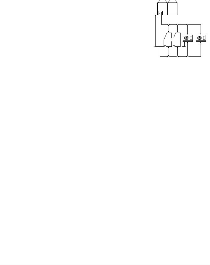
6-1 Wahl des Rohrleitungsmaterials
•Vergewissern Sie sich, dass die Innenund Außenseite der verwendeten Rohrleitungen sauber und frei von Fremdstoffen, wie z. B. Schwefel, Oxid, Staub, Späne, Öl und Fett sowie Wasser, sind.
Es ist wünschenswert, dass die maximale Öladhäsion in den Rohrleitungen 30 mg pro 10 m beträgt.
•Verwenden Sie die folgende Art von Kältemittelleitung.
Material: Nahtloses Kupferrohr mit Phosphor-Desoxidation (C1220T-O für einen maximalen Außendurchmesser von 15,9 mm und C1220T- 1/2H für einen minimalen Außendurchmesser von 19,1 mm)
Größe und Wanddicke der Kältemittelleitung: Ermitteln Sie die Größe und Dicke anhand der folgenden Tabelle.
(Dieses Produkt verwendet R410A. Der Stehdruck des Typs O kann unzureichend sein, wenn er für Rohrleitungen mit einem minimalen Durchmesser von 19,1 mm verwendet wird. Verwenden Sie daher den Typ 1/2 H mit einer minimalen Dicke von 1,0 mm. Wird der Typ O für Rohrleitungen mit einem minimalen Durchmesser von 19,1 mm verwendet, ist eine minimale Dicke von 1,2 mm erforderlich. Führen Sie in diesem Fall unbedingt Hartlöten jeder Verbindung durch.)
•Führen Sie die Verrohrung innerhalb des in der folgenden Tabelle angegebenen Bereichs durch.
Länge der Kältemittelleitung
Max. zulässige Einweg- |
LRMEQ5~20AY1 |
a + b + c + d ≤ 130m (d ist d1 oder d2, welches Maß von beiden länger ist) |
Rohrlänge |
|
|
|
a + b + c + d ≤ 70m (d ist d1 oder d2, welches Maß von beiden länger ist) |
|
(entsprechende Länge) |
LRLEQ5~20AY1 |
|
|
|
|
Max. Zweigleitungslänge (tatsächliche Länge) |
b + c + d ≤ 30m (d ist d1 oder d2, welches Maß von beiden länger ist) |
|
|
|
|
Max. Höhenunterschied |
Gerät unter Außengerät |
H ≤ 35m (Hinweis) |
zwischen Innenund |
|
|
|
H ≤ 10m |
|
Außengerät |
Gerät über Außengerät |
|
|
|
|
Höhenunterschied zwischen Innengeräten |
H1 ≤ 0,5m |
|
|
|
|
|
Hinweis: Ein Siphon ist in 5-m-Intervallen vom Außengerät erforderlich. |
|
Kältemittelleitungsgröße |
|
|
|
|
|
|
Außenaggregat |
|
|
|
Flüssigkeitsleitung |
|||
|
<![if ! IE]> <![endif]>Gasleitung |
A |
B |
C |
D2 |
H |
F |
E |
D1 |
|
|
|
|
||||
|
|
|
Vitrine |
|
|
|
|
|
|
H1 |
Geräte- |
|
|
f |
e |
d1 |
kühler |
|
|
|
|||
|
|
a |
b |
c |
d2 |
(MT (Mittlere Temperatur)) LRMEQ5~20AY1 |
|
|
|
|
|
|
(Einheit:mm) |
|
|||||
|
|
|
|
|
|
|
|
|
|
|
|
|
|
|
|
Rohreitungsgröße |
|
|
|
|
|
|
|
|
|
||
Außengeräteseite |
Flüssigkeitsseitige Rohrleitung |
|
|
Gasseitige Rohrleitung |
|
|
|
|
|||||
|
|
50m oder weniger |
50~130m |
|
|
50m oder weniger |
50~130m |
|
|
||||
Typ 5A · 6A |
φ9,5 × 0,8 (Typ O) |
φ12,7 × 0,8 (Typ O) |
φ19,1 × 1,0 (Typ 1/2H) |
φ22,2 × 1,0 (Typ 1/2H) |
|
|
|||||||
|
|||||||||||||
Typ 8A · 10A · 12A |
φ9,5 × 0,8 (Typ O) |
φ12,7 × 0,8 (Typ O) |
φ25,4 × 1,0 (Typ 1/2H) |
φ28,6 × 1,0 (Typ 1/2H) |
|
|
|||||||
Typ 15A · 20A |
φ12,7 × 0,8 (Typ O) |
φ15,9 × 0,8 (Typ O) |
φ31,8 × 1,1 (Typ 1/2H) |
φ34,9 × 1,1 (Typ 1/2H) |
|
|
|||||||
Rohrleitungen zwischen |
Wählen Sie die Rohrleitungen entsprechend der Gesamtkapazität der abwärts |
|
|
||||||||||
Zweigbereichen (B, b, C, c) |
angeschlossenen Innengeräte in der nachstehenden Tabelle aus. |
|
|
|
|
||||||||
|
|
|
|
|
|
|
|
|
|
|
|||
|
|
|
Gesamtkapazität der Innengeräte nach der Verzweigung |
|
Gasrohrgröße |
|
Flüssigkeitsrohrgröße |
|
|
|
|||
|
|
|
Weniger als 6,0 kW |
|
|
|
φ12,7 × 0,8 (Typ O) |
|
φ6,4 × 0,8 (Typ O) |
|
|
|
|
|
|
|
6,0 kW oder mehr, aber weniger als 9,9 kW |
|
φ15,9 × 1,0 (Typ 1/2H) |
|
|
|
|
|
|||
|
|
|
9,9 kW oder mehr, aber weniger als 14,5 kW |
|
φ19,1 × 1,0 (Typ 1/2H) |
|
φ9,5 × 0,8 (Typ O) |
|
|
|
|||
|
|
|
14,5 kW oder mehr, aber weniger als 18,5 kW |
|
φ22,2 × 1,0 (Typ 1/2H) |
|
|
|
|
||||
|
|
|
|
|
|
|
|
|
|||||
|
|
|
18,5 kW oder mehr, aber weniger als 25,0 kW |
|
φ25,4 × 1,0 (Typ 1/2H) |
|
|
|
|
|
|||
|
|
|
25,0 kW oder mehr, aber weniger alsn 31,0 kW |
|
φ28,6 × 1,0 (Typ 1/2H) |
|
φ12,7 × 0,8 (Typ O) |
|
|
|
|||
|
|
|
31,0 kW oder mehr |
|
|
|
φ31,8 × 1,1 (Typ 1/2H) |
|
|
|
|
||
|
|
|
|
|
|
|
|
|
|
|
|||
|
|
Keine Größe nach der Verzweigung darf die Größe einer vorgelagerten Rohrleitung überschreiten. |
|
|
|||||||||
|
|
|
|
|
|
|
|
||||||
Rohrleitung zwischen Zweigbereichen und dem jeweiligen Gerät |
Stellen Sie die Größe der Rohrleitungen so ein, dass sie mit der Größe der Verbindungsleitung zum Innengerät übereinstimmt. |
|
|
||||||||||
|
|
|
|
|
|
|
|
|
|
|
|
|
|
(LT (Niedrige Temperatur)) LRLEQ5~20AY1 |
|
|
|
|
|
|
(Einheit:mm) |
|
|||||
|
|
|
|
|
|
|
|
|
|
|
|
||
|
|
Rohreitungsgröße |
|
|
|
|
|
|
|
|
|
||
Außengeräteseite |
Flüssigkeitsseitige Rohrleitung |
|
|
Gasseitige Rohrleitung |
|
|
|
|
|||||
|
|
50m oder weniger |
50~70m |
|
|
25m oder weniger |
25~70mm |
|
|
||||
Typ |
5A · 6A |
φ9,5 × 0,8 |
(Typ O) |
φ12,7 × 0,8 |
(Typ O) |
φ19,1 × 1,0 (Typ 1/2H) |
φ22,2 × 1,0 (Typ 1/2H) |
|
|
||||
Typ |
8A · 10A · 12A |
φ9,5 × 0,8 |
(Typ O) |
φ12,7 × 0,8 |
(Typ O) |
φ25,4 × 1,0 (Typ 1/2H) |
φ28,6 × 1,0 (Typ 1/2H) |
|
|
||||
Typ 15A · 20A |
φ12,7 × 0,8 |
(Typ O) |
φ15,9 × 0,8 |
(Typ O) |
φ31,8 × 1,1 (Typ 1/2H) |
φ34,9 × 1,1 (Typ 1/2H) |
|
|
|||||
Rohrleitungen zwischen |
Wählen Sie die Rohrleitungen entsprechend der Gesamtkapazität der abwärts |
|
|
||||||||||
Zweigbereichen (B, b, C, c) |
angeschlossenen Innengeräte in der nachstehenden Tabelle aus. |
|
|
|
|
||||||||
|
|
|
|
|
|
|
|
||||||
|
|
|
Gesamtkapazität der Innengeräte nach der Verzweigung |
|
Gasrohrgröße |
|
Flüssigkeitsrohrgröße |
|
|
|
|||
|
|
|
Weniger als 2,3 kW |
|
|
|
φ12,7 × 0,8 (Typ O) |
|
φ6,4 × 0,8 (Typ O) |
|
|
|
|
|
|
|
2,3 kW oder mehr, aber weniger als 4,4 kW |
|
φ15,9 × 1,0 (Typ 1/2H) |
|
|
|
|
|
|||
|
|
|
4,4 kW oder mehr, aber weniger als 6,4 kW |
|
φ19,1 × 1,0 (Typ 1/2H) |
|
φ9,5 × 0,8 (Typ O) |
|
|
|
|||
|
|
|
6,4 kW oder mehr, aber weniger als 7,8 kW |
|
φ22,2 × 1,0 (Typ 1/2H) |
|
|
|
|
||||
|
|
|
|
|
|
|
|
|
|||||
|
|
|
7,8 kW oder mehr, aber weniger als 10,8 kW |
|
φ25,4 × 1,0 (Typ 1/2H) |
|
|
|
|
|
|||
|
|
|
10,8 kW oder mehr, aber weniger als 13,4 kW |
|
φ28,6 × 1,0 (Typ 1/2H) |
|
φ12,7 × 0,8 (Typ O) |
|
|
|
|||
|
|
|
13,4 kW oder mehr |
|
|
|
φ31,8 × 1,1 (Typ 1/2H) |
|
|
|
|
||
|
|
|
|
|
|
|
|
|
|
|
|||
|
|
Keine Größe nach der Verzweigung darf die Größe einer vorgelagerten Rohrleitung überschreiten. |
|
|
|||||||||
|
|
|
|
||||||||||
Rohrleitung zwischen Zweigbereichen und dem jeweiligen Gerät |
Stellen Sie die Größe der Rohrleitungen so ein, dass sie mit der Größe der Verbindungsleitung zum Innengerät übereinstimmt. |
|
|
||||||||||
|
|
|
|
|
|
|
|
|
|
|
|
|
|
Deutsch |
7 |
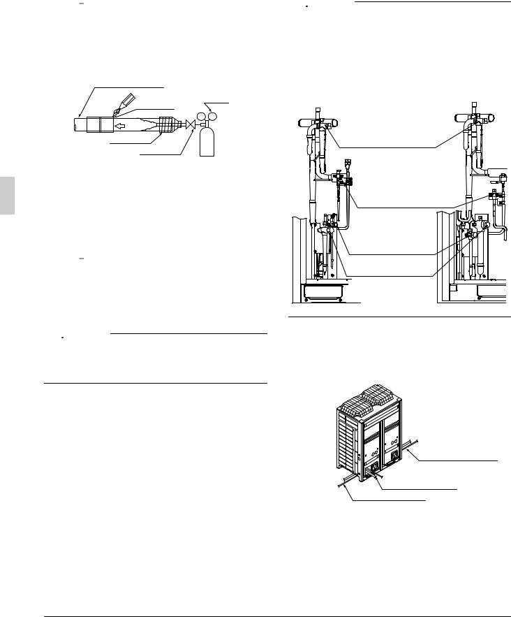
6-2 Schutz gegen Verunreinigung bei der Installation der Rohre
Schützen Sie die Rohrleitungen vor dem Eindringen von Feuchtigkeit, Schmutz, Staub usw.
Ort |
Installationszeitraum |
Schutzmethode |
|
|
|
|
|
Außengerät |
Länger als ein Monat |
Quetschen des Rohrs |
|
|
|
||
Weniger als ein Monat |
Quetschen oder Umwick- |
||
|
|||
Innengerät |
Ungeachtet des Zeitraums |
eln des Rohrs |
|
|
|
|
Hinweis

Lassen Sie besondere Vorsicht walten, wenn Sie Rohrleitungen durch Löcher in Wänden führen oder Rohrenden nach draußen verlegen, um das Eindringen von Schmutz oder Staub zu vermeiden.
6-3 Leitungsverbindung
•Führen Sie beim Löten unbedingt Stickstoffpermutation oder Stickstoffeinblasung durch.
Kühlmittelrohrleitung
Zu lötende |
Regler |
Stelle |
|
Stickstoff
Umwicklung
Handventil
Stickstoff
Löten ohne Stickstoffpermutation oder Stickstoffeinblasung in die Rohrleitungen führt zur Bildung großer Mengen von oxidiertem Film auf der Innenseite der Rohre, wodurch die Ventile und Kompressoren im Kühlsystem beeinträchtigt werden und normaler Betrieb verhindert wird.
•Der Druckregler für die Stickstoffspülung während der Lötarbeit ist auf 0,02 MPa einzustellen (ca. 0,2 kg/cm2: eine leichte Brise ist auf der Wange zu spüren).
Hinweis

Verwenden Sie keine Oxidationsinhibitoren beim Löten der Rohrverbindungen.
Rückstände können die Rohre zusetzen und zu einer Beschädigung der Anlage führen.
6-4 Installation eines Trockners

 ACHTUNG
Dieses Produkt erfordert die Installation eines Trockners am Flüssigkeitsrohr vor Ort.
(Der Betrieb des Geräts ohne installierten Trockner kann zu einem Ausfall der Anlage führen.)
Wählen Sie einen Trockner von der folgenden Tabelle aus:
Modell |
Erforderlicher Trocknerkern |
|
(empfohlener Typ) |
||
|
||
|
|
|
LRMEQ5AY1, LRLEQ5AY1 |
80 g (100% Molekularsieb-Entspre- |
|
chung) |
||
LRMEQ6AY1, LRLEQ6AY1 |
||
(DML083/DML083S: von Danfoss) |
||
|
||
|
|
|
LRMEQ8AY1, LRLEQ8AY1 |
160g (100% Molekularsieb-Entspre- |
|
LRMEQ10AY1, LRLEQ10AY1 |
chung) |
|
LRMEQ12AY1, LRLEQ12AY1 |
(DML163/DML163S : von Danfoss) |
|
|
|
|
LRMEQ15AY1, LRLEQ15AY1 |
160g (100% Molekularsieb-Entspre- |
|
LRMEQ20AY1, LRLEQ20AY1 |
chung) |
|
(DML164/DML164S : von Danfoss) |
||
|
|
•Installieren Sie den Trockner nach Möglichkeit in horizontaler Ausrichtung.
•Installieren Sie den Trockner so nah wie möglich am Außengerät.
•Entfernen Sie den Trocknerdeckel erst unmittelbar vor dem Hartlöten (um Absorption von Feuchtigkeit in der Luft zu verhüten).
•Befolgen Sie die Anweisungen in der Betriebsanleitung des Trockners bezüglich des Hartlötens.
•Reparieren Sie etwaige Verbrennungen des Trocknerlacks, die während des Hartlötens auftreten.
Kontaktieren Sie den Hersteller für weitere Informationen zum Ausbesserungslack.
•Bei manchen Trocknertypen ist die Strömungsrichtung angegeben.
Stellen Sie die Strömungsrichtung gemäß der Betriebsanleitung des Trockners ein.
6-5 Anschluß der Kältemittelleitungen

 ACHTUNG
•Zusätzlich zu den Gasund Flüssigkeitsabsperrventilen besitzt dieses Gerät ein Wartungsabsperrventil (siehe nachstehende Abbildung).
•Betätigen Sie nicht das Wartungsabsperrventil*.
(Die Werkseinstellung für das Wartungsabsperrventil ist “offen”. Lassen Sie dieses Ventil während des Betriebs immer in der offenen Stellung. Der Betrieb des Geräts in geschlossener Stellung des Ventils kann einen Ausfall des Kompressors verursachen.)
*Wartungsabsperrventil
* Wartungsabsperrventil
Flüssigkeitsseiten-
Absperrventil
(mit Wartungsanschluss)
Gasseiten-Absperrventil
(mit Wartungsanschluss)
1.Richtung zum Herausführen der Rohre
Die lokalen Geräteverbindungsleitungen können entweder vorn oder seitlich angeschlossen werden (Herausführung durch die Unterseite), wie in der nachstehenden Abbildung gezeigt.
Bei Herausführung durch die Unterseite die Vorprägungsöffnung im Bodenrahmen verwenden.
Anschluss rechte Seite
Anschluss Vorderseite
Anschluss linke Seite
8 |
Deutsch |
Vorsichtsmaßnahmen beim Ausschlagen der vorgeprägten Öffnungen
•Die vorgeprägte Öffnung im Sockelrahmen durch Ausbohren der 4 umliegenden Vertiefungen mit einem 6-mm-Bohrer öffnen.
Vorgeprägte
Öffnung Bohrer
Vertiefung
(4 Stellen)
•Beschädigung des Gehäuses vermeiden
•Nach dem Ausschlagen der Vorprägungen ist es empfehlenswert, etwaige Grate zu entfernen und mit Ausbesserungslack zu lackieren, um Rostbildung vorzubeugen.
•Beim Durchführen von Kabeln durch die vorgeprägten Öffnungen sind die Kabel mit einem Schutzrohr oder Buchsen zu schützen, um Beschädigung zu vermeiden.
2.Entfernen der Quetschleitung
Wenn Kältemittelleitungen an das Außengerät angeschlossen werden, sind die Stützrohre wie im folgenden Verfahren zu entfernen.
Siehe “Funktionsweise des Absperrventils” zur Handhabung des Absperrventils.
Flüssigkeitsund Gasseiten-Absperrventil
Verfahren 1
Sicherstellen, dass das Absperrventil geschlossen ist.
Verfahren 4
Schmelzen Sie das Haltlötmaterial mit einem Brenner, und entfernen Sie die Quetschleitung (groß), nachdem das Gas in der Quetschleitung abgelassen worden ist.
Füllschlauch
Wartungsanschluss 
 Verfahren 2
Schließen Sie einen Füllschlauch an den Wartungsanschluss der Absperrventile auf der Flüssigkeits-
und Gasseite an, und entfernen
Sie das Gas von der Quetschleitung.
Quetschleitung
Rohrleitungen auf der
Produktseite
Wartungsanschluss
Vor-Ort-Verrohrung
Quetschleitung (Große)
Quetschleitung (Klein)
Abschneiden
Verfahren 3
Schneiden Sie die Quetschleitung (klein) mit einem geeigneten Werkzeug, wie z. B. einem Rohrschneider, ab und öffnen Sie den Querschnitt, um zu prüfen, dass kein Restöl vorhanden ist.
Hinweis: Falls Öl aus dem Querschnitt austritt, schneiden Sie die Quetschleitung (groß) mit einem Rohrschneider ab, und entfernen Sie die Quetschleitung.


 WARNUNG
Trennen Sie die Quetschleitung ab, nachdem Sie das Kältemittelgas in den Rohrleitungen eingesammelt haben.
Die Rohrleitungen können explodieren, und Verletzungen können durch Schmelzen der Hartlotlegierung verursacht werden, wenn das Gas in den Rohrleitungen nicht vollständig abgelassen wird.
Funktionsweise des Absperrventils
Befolgen Sie die nachstehenden Anweisungen zur Betätigung des jeweiligen Absperrventils.

 ACHTUNG
•Betätigen Sie das Absperrventil nicht, bevor die in “8-3 Überprüfen des gerätes und der Installationsbedingungen” beschriebenen Schritt abgeschlossen sind.
Lassen Sie das Absperrventil nicht geöffnet, ohne die Stromversorgung einzuschalten, weil sonst Kältemittel im Kompressor kondensieren und die Isolierung des Hauptstromversorgungskreises sich verschlechtern kann.
•Verwenden Sie unbedingt ein Spezialwerkzeug für die Handhabung des Absperrventils. Das Absperrventil ist keine Rückblattausführung. Bei Ausübung einer übermäßigen Kraft kann das Ventil beschädigt werden.
•Verwenden Sie einen Füllschlauch für den Wartungsanschluss.
•Vergewissern Sie sich, dass kein Kältemittelgas ausströmt, nachdem Ventildeckel und Kappe fest angezogen worden sind.
Anzugsmoment
Überprüfen Sie anhand der folgenden Tabelle die Größen der vom jeweiligen Modell verwendeten Absperrventile sowie die Anzugsmomente der entsprechenden Absperrventile.
Absperrventilgrößen
|
Typ 5A |
Typ 6A |
Typ 8A |
Typ 10A |
Typ 12A |
Typ 15A |
Typ 20A |
|
|
|
|
|
|
|
|
Flüssigkeitsseiten- |
|
|
φ9,5 |
|
|
φ12,7 |
|
Absperrventil |
|
|
|
|
|||
|
|
|
|
|
|
|
|
Gasseiten- |
φ19,1 |
|
φ25,4 |
|
φ31,8 |
||
Absperrventil |
|
|
|||||
|
|
|
|
|
|
|
|
|
|
|
|
|
|
|
|
Wartungsanschluss
Ventildeckel
Dichtungsteil |
|
|
Sechskantloch |
||
|
Schaft |
|
|||
|
|
|
|
||
|
|
|
|
|
|
Absperrven- |
Anzugsmoment N•m (schließt im Uhrzeigersinn) |
||||
|
|
|
|
|
|
|
|
|
|
Wartungsa- |
|
tilgrößen |
Schaft (Ventilkörper) |
|
Ventildeckel |
||
|
nschluss |
||||
|
|
|
|
|
|
|
|
|
|
|
|
φ9,5 |
5,4~6,5 |
Sechskant- |
|
13,5~16,5 |
|
φ12,7 |
8,1~9,9 |
schlüssel: 4mm |
|
18,0~22,0 |
|
|
|
|
|
|
|
φ19,1 |
27,0~33,0 |
Sechskant- |
|
22,5~27,5 |
11,5~13,9 |
φ25,4 |
schlüssel: 8mm |
|
|||
|
|
|
|
||
|
|
|
|
|
|
φ31,8 |
26,5~29,4 |
Sechskant- |
|
44,1~53,9 |
|
schlüssel: 10mm |
|
|
|||
|
|
|
|
|
|
|
|
|
|
|
|
Öffnungsmethode
1.Den Ventildeckel entfernen, und den Schaft mit einem Sechskantschlüssel entgegen dem Uhrzeigersinn drehen.
2.Den Schaft bis zum Anschlag drehen.
3.Den Ventildeckel sicher festziehen. Das für die Größe geeignete Anzugsmoment ist aus der obigen Tabelle ersichtlich.
Schließmethode
1.Den Ventildeckel entfernen, und den Schaft mit einem Sechskantschlüssel im Uhrzeigersinn drehen.
2.Die Welle anziehen, bis sie mit dem Dichtungsteil des Ventils in Berührung kommt.
3.Den Ventildeckel sicher festziehen. Das für die Größe geeignete Anzugsmoment ist aus der obigen Tabelle ersichtlich.
Handhabungsvorkehrungen für Ventildeckel
•Achten Sie darauf, dass der Dichtungsteil nicht beschädigt wird.
•Bei der Anbringung des Ventildeckels ein Gewindebindemittel auf das Schraubengewinde auftragen.
•Kein Gewindebindemittel (für Bördelmutter) auf den Dichtungsteil auftragen.
Deutsch |
9 |
•Ziehen Sie den Ventildeckel nach dem Betätigen des Ventils sicher fest. Siehe “Funktionsweise des Absperrventils” für das Anzugsmoment des Ventils.
|
Schraubengewinde |
|
Gewindebindemittel |
Ventildeckel |
auftragen |
|
Absperrventil |
|
Teil bei Anbringung |
Dichtungsteil |
des Ventildeckels. |
Kein Gewindebindemittel |
|
auftragen |
|
Handhabungsvorkehrungen für den Wartungsanschluss
•Verwenden Sie für den Wartungsanschluss einen Füllschlauch mit Druckstange.
•Bei der Anbringung der Kappe ein Gewindebindemittel auf das Schraubengewinde auftragen.
•Kein Gewindebindemittel (für Bördelmutter) auf den Dichtungsteil auftragen.
•Ziehen Sie die Kappe nach der Arbeit sicher fest. Siehe “Funktionsweise des Absperrventils” für das Anzugsmoment der Kappe.
|
Kappe |
Dichtungsteil |
|
Kein Gewindebindemittel |
Schraubengewinde |
auftragen |
Gewindebindemittel |
|
auftragen |

 ACHTUNG
Tragen Sie Gewindebindemittel auf die Ventildeckelhalterung und das Schraubengewinde des Wartungsanschlusses auf.
Anderenfalls kann Kondenswasser ins Innere eindringen und gefrieren. Daher kann es durch Verformung oder Beschädigung der Kappe zu Ausströmen von Kältemittelgas oder einer Funktionsstörung des Kompressors kommen.
3. Anschließen der Kältemittelleitungen an die Außengeräte
Bei Anschluss an der Vorderseite
Entfernen Sie zum Anschluss die Abdeckung des Absperrventils.
Flüssigkeitsseiten-Absperrventil
Gasseiten-
Absperrventil
Lötstelle
Rohr für Gasseite (1)
Rohr für
Flüssigkeitsseite (1)
Bei Anschluss an der Seite (Unterseite)
Die Vorprägung am Bodenrahmen ausbrechen, und die Rohrleitungen unter dem Bodenrahmen verlegen.
[Typ 5A, 6A]
FlüssigkeitsseitenAbsperrventil
Gasseiten- |
|
|
Absperrventil |
Lötstelle |
|
Rohr für |
Vorprägungsöffnung |
|
Gasseite (2) |
||
Die Vorprägungsöffnung |
||
|
||
Lötstelle |
ausbrechen. |
|
|
||
Flüssigkeitsseitige |
|
|
Leitung |
Rohr für |
|
(vor Ort zu beschaffen) |
Flüssigkeitsseite (2) |
|
Gasseitige Leitung |
|
|
(vor Ort zu beschaffen) |
|
|
[Typ 8A, 10A, 12A, 15A, 20A] |
|
|
Gasseiten- |
Flüssigkeitsseiten- |
|
Absperrventil |
||
Absperrventil |
Lötstelle |
|
|
||
Rohr für |
Vorprägungsöffnung |
|
Gasseite (1) |
||
Die Vorprägungsöffnung |
||
|
||
Lötstelle |
ausbrechen. |
|
|
||
Flüssigkeitsseitige |
Rohr für |
|
Leitung |
||
(vor Ort zu beschaffen) |
Flüssigkeitsseite (2) |
Gasseitige Leitung (vor Ort zu beschaffen)

 ACHTUNG
•Prüfen Sie, dass die Vor-Ort-Rohrleitungen nicht mit anderen Rohrleitungen, dem Bodenrahmen oder der Seitenplatte des Produkts in Berührung kommen.
Vorsichtsmaßnahmen für Rohrleitungen
Beachten Sie bei der Durchführung von Rohrverzweigungen die folgenden Bedingungen.
•Verwenden Sie zum Verzweigen des Flüssigkeitsrohrs einen T- Verbinder oder einen Y-Verbinder, und führen Sie die Verzweigung horizontal aus. Dies verhindert ungleichmäßigen Fluss des Kältemittels.
•Verwenden Sie zum Verzweigen des Gasrohrs einen T-Verbinder, und führen Sie die Verzweigung so aus, dass sich die Zweigleitung über der Hauptleitung befindet (siehe die nachstehende Abbildung). Dadurch wird verhindert, dass Kältemittelöl im ruhenden Innengerät verbleibt.
•Verwenden Sie einen Y-Verbinder für die KältemittelflüssigkeitsZweigleitung, und führen Sie die Rohrverzweigung horizontal aus.
Y-Verbinder |
Horizontale |
|
|
Fläche |
±30˚ oder |
|
|
weniger |
A |
A-Pfeil-Ansicht |
|
|
|
•Verwenden Sie einen T-Verbinder für die Kältemittelgas-Zweigle- itung, und nehmen Sie den Anschluss auf der Oberseite der Hauptleitung vor.
T-Verbinder
Hauptleitung
10 |
Deutsch |

|
Innengeräteseite |
|
|
|
Zweigleitung |
|
T-Verbinder |
Die Rohrleitung |
|
abwärts neigen |
|
|
|
|
|
|
Hauptleitung |
|
|
Die Rohrleitung |
Zweigleitung |
|
abwärts neigen |
|
|
|
Die Rohrleitung |
|
Außengeräteseite |
abwärts neigen |
|
|
|
|
|
•Vergewissern Sie sich, dass der horizontale Abschnitt der Gasleitung zum Außengerät hin abwärts geneigt ist (siehe die obige Abbildung).
•Falls das Außengerät höher liegt, bringen Sie Siphons am Gasrohr in 5-m-Abständen vom Außengerät an. Dies gewährleistet problemlose Rückführung von Öl in der aufwärts geneigten Rohrleitung.
7.BAUSEITIGE VERDRAHTUNG
An Elektroinstallateure
•Installieren Sie unbedingt einen Fehlerstrom-Schutzschalter. Das Produkt enthält Wechselrichterteile. Um eine Funktionsstörung des Fehlerstrom-Schutzschalters zu verhüten, stellen Sie sicher, dass er Oberschwingungen standhält.
•Benutzen Sie das Kondensatorgerät nicht eher, bis die Verlegung der Kältemittelleitungen abgeschlossen ist, weil sonst eine Funktionsstörung des Kompressors auftritt.
•Entfernen Sie keine elektrischen Komponenten, wie z. B. Thermistoren oder Sensoren, wenn Sie Stromversorgungskabel oder Übertragungskabel anschließen. Es kann zu einer Funktionsstörung des Kompressors kommen, falls die Klimaanlage ohne solche elektrischen Komponenten betrieben wird.

 ACHTUNG
•Sämtliche bauseitigen Verdrahtungen und Bauteile müssen von einem zugelassenen Elektriker installiert werden und den entsprechenden örtlichen und staatlichen Vorschriften entsprechen.
•Es muß eine eigene Netzleitung vorhanden sein. Verwenden Sie nie eine Netzleitung zusammen mit anderen Geräten.
•Auf keinen Fall einen Phasenverschiebungskondensator installieren. Da dieses Gerät mit einem Wechselrichter ausgestattet ist, wird durch den Einbau eines Phasenverschiebungskondensators nicht nur der Leistungsfaktor-Verbesserungseffekt verschlechtert, sondern es kann auch zu einer abnormalen Kondensatorerwärmung durch Hochfrequenzwellen kommen.
•Die Verkabelung erst durchführen, nachdem jegliche Stromzufuhr unterbunden worden ist.
•Kabel sind stets gemäß den relevanten örtlichen und nationalen Bestimmungen zu erden.
•Diese Maschine enthält einen Wechselrichter. Einen Erdleiter anschließen und die Ladung zurücklassen, um die Auswirkung auf andere Geräte zu eliminieren, indem das von einem anderen Wechselrichter erzeugte Rauschen reduziert wird, und um das Aufladen der Außenhülle des Produkts mit Leckstrom zu verhüten.
•Den Erdleiter nicht an Gasrohre, Abwasserrohre, Blitzableiter oder Telefon-Erdleiter anschließen.
Gasrohre: Diese können im Falle eines Gaslecks explodieren oder in Brand geraten.
Abwasserrohre: Bei Verwendung von Hartplastikrohren ist kein Erdungseffekt möglich.
Telefon-Erdleiter und Blitzableiter: Gefährlich bei Blitzschlag wegen abnormalen Anstiegs des elektrischen Potentials in der Erdung.
•Unbedingt einen Fehlerstrom-Schutzschalter installieren. Da dieses Gerät einen Wechselrichter verwendet, muss ein
Fehlerstrom-Schutzschalter installiert werden, der hohe Oberschwingungen verarbeiten kann, um eine Funktionsstörung des Fehlerstrom-Schutzschalters selbst zu verhüten.
•Ein Fehlerstrom-Schutzschalter, der speziell für den Schutz von Masseschluss geeignet ist, sollte in Verbindung mit dem Hauptschalter oder einer Sicherung für die Verkabelung verwendet werden.
•Die elektrische Verkabelung muss gemäß den Schaltplänen und der Beschreibung in dieser Anleitung durchgeführt werden.
•Nicht in Betrieb nehmen, bis die Kältemittelverrohrung abgeschlossen ist.
(Wird die Anlage in Betrieb genommen, bevor die Verrohrung abgeschlossen ist, kann der Kompressor beschädigt werden.)
•Wenn Stromkabel und Übertragungskabel angeschlossen werden, auf keinen Fall einen Thermistor, Sensor usw. ausbauen. (Bei Betrieb ohne Thermistor, Sensor usw. kann der Kompressor beschädigt werden.)
•Dieses Produkt besitzt einen Phasenumkehrschutzdetektor, der nur funktioniert, wenn die Stromversorgung eingeschaltet wird. Falls die Gefahr besteht, dass während des Betriebs des Produkts ein Stromausfall auftritt oder die Stromversorgung ausund wieder eingeschaltet wird, ist eine Phasenumkehrschutzschaltung einzubauen. Der Betrieb des Produkts mit umgekehrter Phase kann zu einer Beschädigung des Kompressors und anderer Teile führen.
•Das Stromkabel sicher anbringen. Die Stromzufuhr mit fehlender N-Phase oder falscher N-Phase führt zu einer Beschädigung des Gerätes.
•Die Stromversorgung auf keinen Fall mit umgekehrter Phase anschließen.
Das Gerät kann mit umgekehrter Phase nicht normal funktionieren. Falls der Anschluss mit umgekehrter Phase vorgenommen wird, sind zwei der drei Phasen zu vertauschen.
•Darauf achten, dass der elektrische Unsymmetriegrad nicht größer als 2 % ist. Wird dieser Wert überschritten, verringert sich die Lebensdauer des Gerätes.
Wird der Wert von 4 % überschritten, schaltet sich das Gerät aus, und ein Störungscode wird auf der Fernbedienung des Innengerätes angezeigt.
•Das vorgeschriebene Kabel sicher anschließen und mit der angebrachten Klemme sichern, ohne äußeren Druck auf die Klemmenteile (Klemme für Stromkabel, Klemme für Übertragungskabel und Erdklemme) auszuüben.
7-1 Beispiel der Verkabelung des ganzen Systems
T1 |
|
Timer |
|
|
|
|
|
Ry0, Ry1 |
|
Relais |
|
|
|
|
|
K1M |
|
Elektromagnetisches Schaltschütz (Abtauheizung) |
|
|
|
|
|
E1H |
|
Abtauheizung |
|
|
|
|
|
S1T |
|
Thermostat für Innentemperatureinstellung |
|
|
|
|
|
S2T |
|
Abtauabschlussthermostat |
|
|
|
|
|
Y1S |
|
Magnetventil |
|
|
|
|
|
H1P |
|
Abtaulampe |
|
|
|
|
|
|
|
9 |
|
|
|
3 |
11 |
|
|
10 |
13 |
|
|
|
|
2 |
4 |
|
|
1 |
|
|
|
|
5 |
|
12 |
|
|
|
14 |
6 7
8
Hinweis: 1. Verwenden Sie einen spannungslosen Kontakt für Mikrostrom für den Fernsteuerschalter (nicht mehr als 1 mA, 12 V DC)
Hinweis: 2. Gesamtkapazität für Warnung, Alarm: 1A oder weniger bei AC 220 bis 240 V.
Kapazität für Betriebsausgabe: 1A oder weniger bei AC 220 bis 240 V.
Deutsch |
11 |
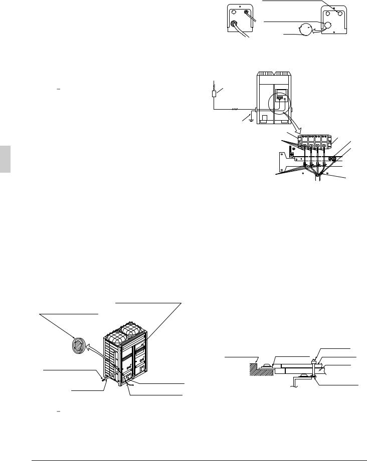
1 3-Phasen-Strom 380~415 V
Fehlerstrom-Schutzschalter (Hochfrequenztyp) (zum Schutz vor Erdschluss, Überlastung und Kurzschluss)
2Außenaggregat
3Fehlerstrom-Schutzschalter (zum Schutz vor Erdschluss, Überlastung und Kurzschluss)
4Hinweis: 1 Fernsteuerschalter
5Hochspannung AC 220~240 V (Siehe Hinweis 2.) Warnungsausgabe
Alarmausgabe Betriebsausgabe
6Warnungseingabe
7Alarmeingabe
8Alarmtafel
9Schalttafel (vor Ort zu beschaffen)
10Timer
11Innenaggregat
12Innenaggregat
13Fehlerstrom-Schutzschalter
14Fehlerstrom-Schutzschalter
Hinweis

•Ein Schutzrohr für Stromversorgungskabel verwenden.
•Achten Sie darauf, dass die Schwachstromkabel (z. B. für die Fernbedienung, zwischen den Geräten usw.) und die Starkstromkabel nicht zu dicht beieinander verlaufen, sondern mindestens 50 mm Abstand haben.
Zu große Nähe kann elektrische Interferenz, Funktionsstörungen und Beschädigung verursachen.
•Schließen Sie die Starkstromkabel an den Starkstrom-Klemmen- block an, und sichern Sie diese gemäß der Beschreibung in “7-2 Verfahren für eingehende Verkabelung”.
•Schließen Sie die Stromversorgung nicht an den Klemmenblock für die Übertragungskabel für Warnungs-, Alarm-, Betriebsausgabe und den Fernbetriebsschalter an. Anderenfalls wird das gesamte System beschädigt.
•Die Übertragungskabel sind gemäß der Beschreibung in “7-3 Verfahren für Stromversorgungsverkabelung” zu sichern.
•Sichern Sie die Kabel mit Klemmen, wie z. B. Isolations-Kabel- bindern, um Kontakt mit den Rohrleitungen zu vermeiden.
•Formen Sie die Kabel, um Strukturen, wie z. B. den Steuerkastendeckel, vor Verformung zu schützen. Schließen Sie den Deckel einwandfrei.
7-2 Verfahren für eingehende Verkabelung
•Führen Sie die Hochspannungskabel (Stromversorgungskabel, Erdleiter und Warnungs-/Alarm-/Betriebskabel) durch die Kabelöffnungen an der Seite oder Front des Geräts (Vorprägungsöffnungen) bzw. am Bodenrahmen (Vorprägungsöffnungen).
•Führen Sie die Niederspannungskabel (für Fernbetriebsschalter) durch die Kabelöffnungen (Vorprägungsöffnungen) an der Vorderseite des Geräts bzw. durch die Kabeleinlässe.
Durchgangs- |
Stromlaufplanaufkleber |
|
(Rückseite des |
||
öffnungsdeckel |
||
Steuerkastendeckels) |
||
Schraffierten |
||
|
||
Bereich |
|
|
ausschneiden |
|
Hochspannungskabel
Rohrleitungsauslass
Schutzrohr
Niederspannungskabel
Hinweis

•Die Vorprägungsöffnungen mit einem Hammer oder dergleichen öffnen.
•Nach dem Ausschlagen der Vorprägungen ist es empfehlenswert, etwaige Grate zu entfernen und mit Ausbesserungslack zu lackieren, um Rostbildung vorzubeugen.
•Beim Durchführen von Kabeln durch die vorgeprägten Öffnungen sind die Kabel mit einem Schutzrohr oder Buchsen zu schützen, um Beschädigung zu vermeiden.
•Falls die Möglichkeit besteht, dass Kleintiere in das Gerät eindringen, sind etwaige Lücken (schraffierte Teile) mit Dichtungsmaterial (vor Ort zu beschaffen) zu blockieren.
Vorprägungsöffnung
(Für Niederspannungskabel)
Vorprägungsöffnung
(Für Hochspannungskabel) 
Grat
7-3 Verfahren für Stromversorgungsverkabelung
Verfahren für Stromversorgungsverkabelung
1
2
B
3
4
5 |
L 1 L 2 L 3 N |
10 |
|
9 |
8
6
7
1Stromversorgung (3-Phasen-Strom 380~415)
2Abzweigschalter oder Überstrom-Schutzschalter (FehlerstromSchutzschalter)
3Erdleiter
4Stromversorgungs-Klemmenblock
5Isolierhülle anbringen
6Die Stromversorgungskabel für die Phasen L1, L2, L3 und N jeweils mit den mitgelieferten Klemmen (1) an der Kunststoffklemme sichern.
7Den Erdleiter mit der mitgelieferten Klemme (1) am Stromversorgungskabel (Phase N) sichern.
8Erdleiter
Die Verkabelung so durchführen, dass der Erdleiter nicht mit den Zuleitungen des Kompressors in Berührung kommt. Anderenfalls kann das erzeugte Rauschen einen schlechten Einfluss auf andere Gerät ausüben.
9Erdungsklemme
10• Wenn zwei Kabel an eine Klemme angeschlossen werden, sind diese so anzuschließen, dass die Rückseiten der Crimpkontakte einander zugewandt sind.
•Außerdem ist darauf zu achten, dass das dünnere Kabel oben liegt, wenn die zwei Kabel gleichzeitig mit der mitgelieferten Klemme (1) am Kunststoffhaken gesichert werden.
|
|
Klemme (1) |
Klemmen-block |
Crimpklemme |
Kabel: schmal |
|
|
Kabel: dick |
|
|
Kunststoffhaken |
Anforderungen an Starkstromkreis, Sicherheitsvorrichtung und Kabel
•Ein Starkstromkreis (siehe die folgende Tabelle) muss für den Anschluss des Gerätes vorhanden sein. Dieser Stromkreis muss mit den erforderlichen Schutzvorrichtungen, z. B. einem Hauptschalter, einer trägen Sicherung für jede Phase und einem Fehlerstrom-Schutzschalter, geschützt werden.
12 |
Deutsch |
 Loading...