


 Loading...
DAIKIN FXTQ12PAVJU, FXTQ18PAVJU, FXTQ24PAVJU, FXTQ30PAVJU, FXTQ36PAVJU INSTALLATION MANUAL
...INSTALLATION MANUAL
 SYSTEM Inverter Air Conditioners
MODELS
Air Handling Unit
FXTQ12PAVJU
FXTQ18PAVJU
FXTQ24PAVJU
FXTQ30PAVJU
FXTQ36PAVJU
FXTQ42PAVJU
FXTQ48PAVJU
FXTQ54PAVJU
English
Français
Español
Read these instructions carefully before installation.
Keep this manual in a handy place for future reference.
This manual should be left with the equipment owner.
Lire soigneusement ces instructions avant l’installation. Conserver ce manuel à portée de main pour référence ultérieure. Ce manuel doit être donné au propriétaire de l’équipement.
Lea cuidadosamente estas instrucciones antes de instalar.
Guarde este manual en un lugar a mano para leer en caso de tener alguna duda. Este manual debe permanecer con el propietario del equipo.
VRV SYSTEM Inverter Air Conditioners |
Installation manual |
|
CONTENTS |
|
1. |
SAFETY CONSIDERATIONS ........................................... |
1 |
2. |
BEFORE INSTALLATION.................................................. |
3 |
3. |
SELECTING INSTALLATION SITE ................................... |
3 |
4. |
PREPARATIONS BEFORE INSTALLATION AND |
|
|
INSTALLATION.................................................................. |
4 |
5. |
REFRIGERANT PIPING WORK ....................................... |
6 |
6. |
DRAIN PIPING WORK...................................................... |
7 |
7. |
INSTALLING THE DUCT................................................... |
8 |
8. |
ELECTRIC WIRING WORK .............................................. |
8 |
9. |
WIRING EXAMPLE........................................................... |
9 |
10. |
FIELD SETTING AND TEST RUN .................................. |
12 |
1.SAFETY CONSIDERATIONS
Read these “SAFETY CONSIDERATIONS for Installation” carefully before installing an air conditioner or heat pump. After completing the installation, make sure that the unit operates properly during the startup operation.
Instruct the customer on how to operate and maintain the unit. Inform customers that they should store this Installation Manual with the Operation Manual for future reference.
Always use a licensed installer or contractor to install this product. Improper installation can result in water or refrigerant leakage, electrical shock, fi re, or explosion.
Meanings of DANGER, WARNING, CAUTION, and NOTE
Symbols:
DANGER................ |
Indicates an imminently hazardous |
|
situation which, if not avoided, will |
|
result in death or serious injury. |
WARNING .............. |
Indicates a potentially hazardous |
|
situation which, if not avoided, could |
|
result in death or serious injury. |
CAUTION ............... |
Indicates a potentially hazardous |
|
situation which, if not avoided, may |
|
result in minor or moderate injury. |
|
It may also be used to alert against |
|
unsafe practices. |
NOTE...................... |
Indicates situations that may result in |
|
equipment or property-damage |
|
accidents only. |
 DANGER
•Refrigerant gas is heavier than air and replaces oxygen. A massive leak can lead to oxygen depletion, especially in basements, and an asphyxiation hazard could occur leading to serious injury or death.
•Do not ground units to water pipes, gas pipes, telephone wires, or lightning rods as incomplete grounding can cause a severe shock hazard resulting in severe injury or death. Additionally, grounding to gas pipes could cause a gas leak and potential explosion causing severe injury or death.
•If refrigerant gas leaks during installation, ventilate the area immediately. Refrigerant gas may produce toxic gas if it comes in contact with fire. Exposure to this gas could cause severe injury or death.
•After completing the installation work, check that the refrigerant gas does not leak throughout the system.
•Do not install unit in an area where flammable materials are present due to risk of explosions that can cause serious injury or death.
•Safely dispose all packing and transportation materials in accordance with federal/state/local laws or ordinances. Packing materials such as nails and other metal or wood parts, including plastic packing materials used for transportation may cause injuries or death by suffocation.
 WARNING
•All phases of the field-installation, including, but not limited to, electrical, piping, safety, etc. must be in accordance with manufacturer's instructions and must comply with national, state, provincial and local codes.
•Only qualified personnel must carry out the installation work. Installation must be done in accordance with this installation manual. Improper installation may result in water leakage, electric shock, or fire.
•When installing the unit in a small room, take measures to keep the refrigerant concentration from exceeding allowable safety limits. Excessive refrigerant leaks, in the event of an accident in a closed ambient space, can lead to oxygen deficiency.
•Use only specified accessories and parts for installation work. Failure to use specified parts may result in water leakage, electric shocks, fire, or the unit falling.
•Install the air conditioner or heat pump on a foundation strong enough that it can withstand the weight of the unit. A foundation of insufficient strength may result in the unit falling and causing injuries.
•Take into account strong winds, typhoons, or earthquakes when installing. Improper installation may result in the unit falling and causing accidents.
•Make sure that a separate power supply circuit is provided for this unit and that all electrical work is carried out by qualified personnel according to local, state, and national regulations. An insufficient power supply capacity or improper electrical construction may lead to electric shocks or fire.
•Make sure that all wiring is secured, that specified wires are used, and that no external forces act on the terminal connections or wires. Improper connections or installation may result in fire.
•When wiring, position the wires so that the electric component box cover can be securely fastened. Improper positioning of the electric component box cover may result in electric shocks, fire, or the terminals overheating.
•Before touching electrical parts, turn off the unit.
1 |
English |

•It is recommended to install a ground fault circuit interrupter if one is not already available. This helps prevent electrical shocks or fire.
•Securely fasten the outside unit terminal cover (panel). If the terminal cover/panel is not installed properly, dust or water may enter the outside unit causing fire or electric shock.
•When installing or relocating the system, keep the refrigerant circuit free from substances other than the specified refrigerant (R-410A) such as air. Any presence of air or other foreign substance in the refrigerant circuit can cause an abnormal pressure rise or rupture, resulting in injury.
•Do not change the setting of the protection devices. If the pressure switch, thermal switch, or other protection device is shorted and operated forcibly, or parts other than those specified by Daikin are used, fire or explosion may occur.
 CAUTION
•Do not touch the switch with wet fingers. Touching a switch with wet fingers can cause electric shock.
•Do not allow children to play on or around the unit to prevent injury.
•Do not touch the refrigerant pipes during and immediately after operation as the refrigerant pipes may be hot or cold, depending on the condition of the refrigerant flowing through the refrigerant piping, compressor, and other refrigerant cycle parts. Your hands may suffer burns or frostbite if you touch the refrigerant pipes. To avoid injury, give the pipes time to return to normal temperature or, if you must touch them, be sure to wear proper gloves.
•Install drain piping to proper drainage. Improper drain piping may result in water leakage and property damage.
•Insulate piping to prevent condensation.
•Be careful when transporting the product.
•Do not turn off the power immediately after stopping operation. Always wait for at least 5 minutes before turning off the power. Otherwise, water leakage may occur.
•Do not use a charging cylinder. Using a charging cylinder may cause the refrigerant to deteriorate.
•Refrigerant R-410A in the system must be kept clean, dry, and tight.
(a)Clean and Dry -- Foreign materials (including mineral oils such as SUNISO oil or moisture) should be prevented from getting into the system.
(b)Tight -- R-410A does not contain any chlorine, does not destroy the ozone layer, and does not reduce the earth’s protection again harmful ultraviolet radiation. R-410A can contribute to the greenhouse effect if it is released. Therefore take proper measures to check for the tightness of the refrigerant piping installation. Read the chapter Refrigerant Piping and follow the procedures.
•Since R-410A is a blend, the required additional refrigerant must be charged in its liquid state. If the refrigerant is charged in a state of gas, its composition can change and the system will not work properly.
•The indoor unit is for R-410A. See the catalog for indoor models that can be connected. Normal operation is not possible when connected to other units.
•Remote controller (wireless kit) transmitting distance can be shorter than expected in rooms with electronic fluorescent lamps (inverter or rapid start types). Install the indoor unit far away from fluorescent lamps as much as possible.
•Indoor units are for indoor installation only. Outdoor units can be installed either outdoors or indoors. This unit is for indoor use.
•Do not install the air conditioner or heat pump in the following locations:
(a)Where a mineral oil mist or oil spray or vapor is produced, for example, in a kitchen.
Plastic parts may deteriorate and fall off or result in water leakage.
(b)Where corrosive gas, such as sulfurous acid gas, is produced.
Corroding copper pipes or soldered parts may result in refrigerant leakage.
(c)Near machinery emitting electromagnetic waves. Electromagnetic waves may disturb the operation of the control system and cause the unit to malfunction.
(d)Where flammable gas may leak, where there is carbon fiber, or ignitable dust suspension in the air, or where volatile flammables such as thinner or gasoline are handled. Operating the unit in such conditions can cause a fire.
•Take adequate measures to prevent the outside unit from being used as a shelter by small animals. Small animals making contact with electrical parts can cause malfunctions, smoke, or fire. Instruct the customer to keep the area around the unit clean.
 NOTE
NOTE
•Install the power supply and control wires for the indoor and outdoor units at least 3.5 feet away from televisions or radios to prevent image interference or noise. Depending on the radio waves, a distance of 3.5 feet may not be sufficient to eliminate the noise.
•Dismantling the unit, treatment of the refrigerant, oil and additional parts must be done in accordance with the relevant local, state, and national regulations.
•Do not use the following tools that are used with conventional refrigerants: gauge manifold, charge hose, gas leak detector, reverse flow check valve, refrigerant charge base, vacuum gauge, or refrigerant recovery equipment.
•If the conventional refrigerant and refrigerator oil are mixed in R-410A, the refrigerant may deteriorate.
•This air conditioner or heat pump is an appliance that should not be accessible to the general public.
•As design pressure is 450 psi, the wall thickness of field-installed pipes should be selected in accordance with the relevant local, state, and national regulations.
English |
2 |
2.BEFORE INSTALLATION
 WARNING
•Entrust installation to the place of purchase or a qualifi ed serviceman. Improper installation could lead to leaks and, in worse cases, electric shock or fi re.
•Use of unspecifi ed parts could lead to the unit falling, leaks and, in worse cases, electric shock or fi re.
 NOTE
NOTE
•Be sure to read this manual before installing the indoor unit.
•Be sure to mount an air fi lter (part to be procured in the fi eld) in the suction air passage in order to prevent water leaking, etc.
The accessories needed for installation must be retained in your custody until the installation work is completed. Do not discard them.
1.Decide upon a line of transport.
2.Leave the unit inside its packaging while moving, until reaching the installation site. Where unpacking is unavoidable, use a sling of soft material or protective plates together with a rope when lifting, to avoid damage or scratches to the unit.
Be sure to check the type of R410A refrigerant to be used before installing the unit.
(Using an incorrect refrigerant will prevent normal operation of the unit.)
For the installation of an outdoor unit, refer to the installation manual attached to the outdoor unit.
2-1 PRECAUTIONS
•Be sure to instruct customers how to properly operate the unit (operating different functions, and adjusting the temperature) by having them carry out operations themselves while looking at the operation manual.
•Do not install in locations where the air contains high levels of salt such as that near the ocean and where voltage fl uctuates greatly such as that in factories, or in vehicles or vessels.
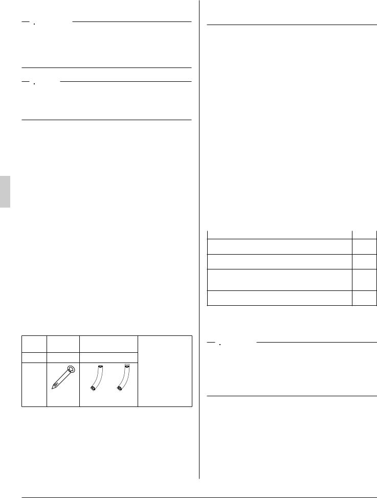
2-2 ACCESSORIES
Check the following accessories are included with your unit.
Name |
Clamp |
Insulation tube |
||
material (1) |
||||
|
|
|
||
Quantity |
4 pcs. |
1 set |
||
|
|
|
(Other) |
|
|
|
|
• Operation manual |
|
|
|
|
• Installation manual |
|
Shape |
|
|
|
|
|
|
Small (2) |
Large (3) |
|
|
|
2 pcs. |
2 pcs. |
|
2-3 OPTIONAL ACCESSORIES
•This indoor unit requires one of the operation remote controls listed below.
|
Remote controller |
|
|
|
|
Wired type |
|
BRC1E71, BRC1D71 |
|
|
|
Wireless type |
|
BRC4C82 |
|
|
|
FOR THE FOLLOWING ITEMS, TAKE SPECIAL CARE DURING CONSTRUCTION AND CHECK AFTER INSTALLATION IS FINISHED.
a.Items to be checked after completion of work
Items to be checked |
If not properly done, what is |
Check |
|
likely to occur |
|||
|
|
||
Are the indoor and outdoor |
The units may drop, vibrate |
|
|
units fi xed fi rmly? |
or make noise. |
|
|
Is the refrigerant leak test |
It may result in insuffi cient |
|
|
fi nished? |
cooling. |
|
|
Is the unit fully insulated? |
Condensate may drip. |
|
|
Does drainage fl ow smoothly? |
Condensate may drip. |
|
|
Does the power supply |
The unit may malfunction or |
|
|
voltage correspond to that |
|
||
the components burn out. |
|
||
shown on the name plate? |
|
||
|
|
||
Are wiring and piping |
The unit may malfunction or |
|
|
correct? |
the components burn out. |
|
|
Is the unit safely grounded? |
Incomplete grounding may |
|
|
result in electric shocks. |
|
||
|
|
||
Is wiring size according to |
The unit may malfunction or |
|
|
specifi cations? |
the components burn out. |
|
|
Is something blocking the air |
It may result in insuffi cient |
|
|
outlet or inlet of either the |
cooling. |
|
|
indoor or outdoor units? |
|
||
|
|
||
Are refrigerant piping length |
The refrigerant charge in |
|
|
and additional refrigerant |
|
||
the system is not clear. |
|
||
charge noted down? |
|
||
|
|
||
Also review the “SAFETY CONSIDERATIONS”. |
|
||
b.Items to be checked at time of delivery |
|
||
|
|
|
|
Items to be checked |
|
Check |
|
Did you explain about operations while showing the operation manual to your customer?
Did you hand the operation manual and warranty over to your customer?
Did you explain to your customer how to maintain and clean local procurements such as the air fi lter, suction grille, and air outlet grille?
Did you hand manuals of local procurements (in case equipped) over to your customer?
3.SELECTING INSTALLATION SITE
 CAUTION
•If you think the humidity inside the installation space might exceed 86°F and RH80%, reinforce the insulation on the unit body.
Use glass wool or polyethylene foam as insulation so that the thickness is more than 2 in. and fi ts inside the installation space opening.
(1)Select an installation site where the following conditions are fulfilled and that meets with your customer’s approval.
•Where optimum air distribution can be ensured.
•Where nothing blocks air passage.
•Where condensate can be properly drained.
•Where the supports are strong enough to bear the indoor unit weight.
•Where the false ceiling is not noticeably on an incline.
•Where suffi cient clearance for maintenance and service can be ensured. (Refer to Fig. 1-1 and Fig. 1-2)
3 |
English |

•Where piping between indoor and outdoor units is possible within the allowable limit. (Refer to the installation manual for the outdoor unit.)
•If a return-air duct is not installed, carefully select the place and method of product installation so that air fl ow into the product will not be blocked.
If installed vertically
(Top view)
24 or more
(length : in.)
 Air outlet
(Front view) |
Fig. 1-1 |
Air inlet |
H |
If installed horizontally
(Front view) |
|
Air inlet |
Air outlet |
|
H |
(Side view)
24 or more
H
Fig. 1-2
 WARNING
•When installing the unit horizontally, be sure to tilt the unit in the direction shown in Fig. 1-2. If the unit is tilted in any other way, water can leak.
•Ensure suffi cient space for the bottom of the product (H dimensions) so that a downward slope of 1/100 can
be maintained for drain piping, as described for the intake duct installation and in “6. DRAIN PIPING WORK”.
[ PRECAUTION ]
•Install the indoor and outdoor units, power supply wiring and connecting wires at least 3.5 ft. away from televisions or radios in order to prevent image interference or noise. (Depending on the radio waves, a distance of 3.3 ft. may not be suffi cient to eliminate the noise.)
•If installing the wireless kit in a room with electronic
fluorescent lighting (inverter or rapid start type), the remote controller’s transmission distance may be shortened. Indoor units should be installed as far away from
fluorescent lighting as possible.
 DANGER
•Do not install unit in an area where fl ammable materials are present due to the risk of an explosion resulting in serious injury or death.
 WARNING
•If the supporting structural members are not strong enough to take the unit’s weight, the unit could fall out of place and cause serious injury.
4.PREPARATIONS BEFORE INSTALLATION AND INSTALLATION
(1)When installing the product, refer to “3. SELECTING INSTALLATION SITE” and consider the product size as shown Fig. 2 and Table 1.
|
|
|
|
Fig. 2 |
|
|
|
D |
|
B |
|
|
1 |
C |
E |
11 |
|
|
|
|
Gas line |
|
A |
|
3-1/4 |
|
|
|
|
|
|
|
|
|
|
|
|
|
Liquid line |
|
|
F |
G |
|
1-1/8 |
|
|
1-3/16 |
H |
(1-3/16) 2-7/8 |
I |
(1-3/16) |
|
|
|
|
|
|
(length: in.) |
English |
4 |
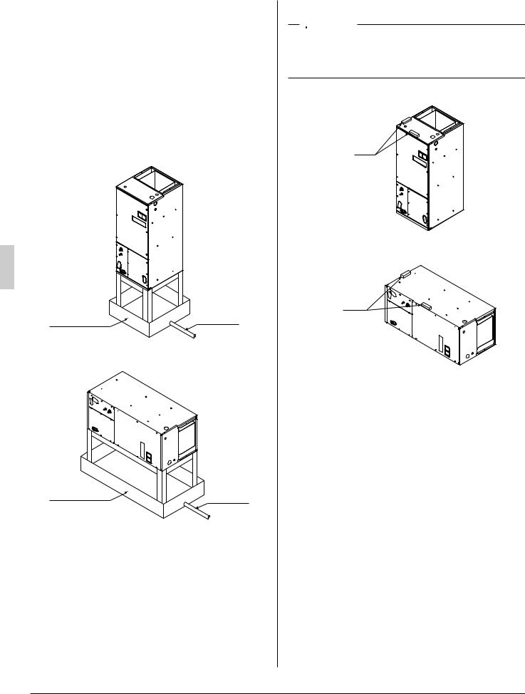
Table 1
|
Model |
A |
B |
C |
D |
E |
F |
G |
H |
I |
||
12 |
· 18 type |
46- |
22 |
17- |
19- |
10 |
14- |
11- |
17- |
17- |
||
3/4 |
1/2 |
1/2 |
1/2 |
15/16 |
1/8 |
15/16 |
||||||
|
|
|
|
|
||||||||
24 |
· 30 |
· 36 · |
53- |
|
|
|
|
14- |
11- |
19- |
19- |
|
42 |
· 48 |
· 54 |
24 |
20 |
22 |
12 |
||||||
1/4 |
1/2 |
15/16 |
5/8 |
15/16 |
||||||||
type |
|
|
|
|
|
|||||||
|
|
|
|
|
|
|
|
|
|
|||
(2)Make sure the range of the unit’s external static pressure is not exceeded. (up to 0.5 in.W.C. at “H” speed.)
(3)Condensation may form on the product during COOL operation. Be sure to provide (field supplied) and install a second drain pan.
If installed vertically
Second drain pan |
Drain piping |
|
If installed horizontally
Second drain pan |
Drain piping |
|
(4) Check if the unit is horizontally level.
 CAUTION
•Make sure the unit is installed level using a level tube: four sides. (One thing to watch out for in particular is if the unit is installed so that the slope is not in the direction of the drain piping, this might cause leaking.)
If installed vertically
Level
If installed horizontally
Level
(5)Secure the unit firmly to prevent it from falling.
(6)When the unit is installed in a hot and humid place, it is recommended to use the following drain pan insulation kit, which is an optional accessory.
|
|
|
Drain pan insulation Kit |
||
|
|
|
|
|
|
|
|
|
Vertically |
Horizontally |
|
|
|
|
|
||
12 |
· 18 type |
DPI 36-42/20 |
DPIH 36-42 |
||
|
|
|
|
|
|
24 |
· 30 |
· 36 · |
DPI 48-60/20 |
DPIH 48-61 |
|
42 |
· 48 |
· 54 type |
|||
|
|
||||
|
|
|
|
|
|
•Regarding the attachment of the drain pan insulation kit, refer to the installation manual provided with the kit.
5 |
English |
Loading...