


Daikin JEHSCU0200M1, JEHSCU0350M3, JEHSCU0200M3, JEHSCU0400M3, JEHSCU0250M1 Installation manuals
...Installation Manual
(Original Instruction)
Scroll condensing unit
for medium temperature application
JEHSCU0200M1 |
JEHSCU0350M3 |
JEHSCU0200M3 |
JEHSCU0400M3 |
JEHSCU0250M1 |
JEHSCU0500M3 |
JEHSCU0250M3 |
JEHSCU0600M3 |
JEHSCU0300M1 |
JEHSCU0680M3 |
JEHSCU0300M3 |
|

Contents
1. |
Nomenclature |
2 |
2. |
Safety and Health |
2 |
3. |
Installation & commissioning |
2 |
4. |
Checklist |
5 |
5. |
Service and Maintenance |
5 |
6. |
Trouble Shooting |
5 |
7. |
Specifications |
6 |
8. |
Outline Drawings |
7 |
9. |
Electrical Data |
8 |
10. |
Declaration of conformity |
11 |
1.Nomenclature
JEHSCU 0200 M 1
1: Single Phase
3: Three Phase
Application
M: Medium Temperature
L: Low Temperature
Nominal Capacity in Horse Power
0200: 2.0 HP
J & E Hall Commercial Scroll Condensing Unit for Daikin
2.Safety and Health
Important Note
Only a qualified refrigeration engineer who is familiar with refrigeration systems and components, including all controls should perform the installation and start-up of the system. To avoid potential injury, use care when working around coil surfaces or sharp edges of metal cabinets. All piping and electrical wiring should be installed in accordance with all applicable codes, ordinances and local by-laws.
•The electrical covers and condenser fan guard must remain fitted at all times.
•Use of the condensing unit outside of design conditions and application for which units were intended may be unsafe and be detrimental to the unit, regardless short or long term operation.
•The condensing units are not designed to withstand loads or stresses from other equipment or personnel. Such extraneous loads or stress may cause failure/leak/injury.
•In some circumstances, a suction accumulator (not supplied) component may be required, it offers protection against refrigerant flood back during operation. It helps protect against off-cycle migration by adding internal free volume to the low side of the system.
•Test must be conducted to ensure the amount of offcycle migration to the compressor does not exceed the compressor’s charge limit.
•Wherever possible the system should be installed to utilize a pump down configuration.
•After installation, the system should be allowed to run for 3 – 4 hours. The oil level should be checked after 3
– 4 hours run time and topped up as necessary. The oil level should be visible at least ½ - ¾ up the compressor oil sight glass. For the details of the oil requirements, please refer to page 5 in the installation & commissioning section and page 5 in the service and maintenance section.
3.Installation & Commissioning
3.1Unit site location
•In order to achieve maximum cooling capacity, the installation location for condensing unit should be carefully selected.
•Install the condensing unit in such a way so that hot air distributed by the condensing unit cannot be drawn in again (as in the case of short circuit of hot discharge air). Allow sufficient space for maintenance around the unit.
General Information
•Ensure the unit received is the correct model for the intended application.
•Ensure refrigerant, voltage, are suitable for the proposed application and environment.
•Installation and maintenance are to be performed only by qualified personnel who are familiar with local codes and regulations, and experienced with this type of equipment.
•The condensing unit is delivered with a nitrogen holding charge.
•The condensing unit contains moving machinery and electrical power hazards. May cause severe injury or death. Disconnect and shut off power before installation or service of the equipment.
•Refrigerant release into the atmosphere is illegal. Proper evacuation, handling and leak testing procedures must be observed at all times.
•Units must be earthed and no maintenance work should be attempted prior to disconnecting the electrical supply.
•Ensure that there is no obstruction of air flow into or out of the unit. Remove obstacles which block air intake or discharge.
•The location must be well ventilated, so the unit can draw in and distribute plenty of air thus lowering the condensing temperature.
•To optimize the unit running conditions, the condenser coil must be cleaned at regular intervals.
Rev 001/January 2010 |
2 |
All specifications are subjected to change by the manufacturer without prior notice. The English text is the original instruction. Other languages are the translations of the original instructions.

3.2 Installation Clearance
•The installation location should allow sufficient space for air flow and maintenance around the unit.
•To allow sufficient space for doing service or installation.
3.3 Field Piping
Important Note
Line sizing should only be determined by qualified personnel. All local codes of practice must be observed in the installation of refrigerant piping
To ensure satisfactory operation and performance, the following points should be noted for field piping arrangements,
•Pipework routes must be as simple and as short as possible.
•Avoid low points on pipework where oil can accumulate.
•Correct line sizing will minimize the pressure drop and maintain sufficient gas velocity for proper oil return.
•Use only clean, dehydrated refrigeration grade copper tube with large radius elbows.
•Braze without over filling to ensure there is no excess solder into the tube.
•To prevent oxidation, blow nitrogen through pipework when brazing.
•Install insulation on all suction lines.
•Adequately support all pipe work at a maximum of 2 meter intervals.
•In vertical pipework, the use of U-trap and double suction risers is often required. These suction risers must always be fitted with a U-trap at the bottom and a P-trap at the top and never be higher than 4 meter unless a second U-trap system is fitted.
•Recommend piping length less than 25m. Additional oil might be required if piping length exceeds 20m or with many oil traps. Normally quantity of top up oil required should not exceed 2% of the total refrigerant charge.
3.4 Pressure testing
•When running a pressure test, always use an inert, dry gas such as Nitrogen
•The pressure differential between the high and low side should not exceed 30 bar (435 psig)
•Test pressures are :
19 bar (275 psig) on the Low Side
28 bar (405 psig) on the High Side
3.5 Leak detection
•Make sure that all manual valves are open
•Perform a leak test of the system using nitrogen mixed with the refrigerant to be used
•Do not use CFC for leak testing the condensing unit which will be used with HFC refrigerants
•The use of leak testing fluids is not recommended as this may interact with the lubricants own additives
3.6 Vacuum - moisture removal
Important Note
Moisture prevents proper functioning of the compressor and the refrigeration system
Air and moisture reduce service life and increase condensing pressure causing abnormally high discharge temperatures likely to destroy the oil’s lubricating properties. The risk of acid formation is also increased by air and moisture and copper plating can be generated in this way. All these phenomena can be cause mechanical and electrical failure.
Important Note
Ensure that a good quality vacuum pump is used to pull a minimum vacuum of 250 microns (0.33 mbar)
3.7 Safety pressure switch settings
The pressure switch fitted to condensing units with auto reset for low pressure and manual reset for high pressure are NOT factory preset.
1. |
Low pressure (LP) setting spindle |
12. |
Switch |
2. |
Differential setting spindle, LP |
13. |
Terminals |
3. |
Main arm |
14. |
Earth terminal |
5. |
High pressure (HP) setting spindle |
15. |
Cable entry |
7. |
Main spring |
16. |
Tumbler |
8. |
Differential spring |
18. |
Locking plate |
9. |
Bellows |
19. |
Arm |
10. LP connection |
20. |
Manual reset button |
|
11. HP connection |
|
|
|
High pressure safety (Manual reset)
The high pressure safety switch is required to stop the compressor, should the discharge pressure exceed the values shown in the following table. The high pressure switch can be set to lower values depending on the application and the ambient conditions
Model |
Series 2, 3 |
|
|
|
|
Refrigerant |
R404A |
R134a |
|
|
|
Cut Out (bar g) |
28 |
23 |
|
|
|
Cut Out (psi g) |
405 |
330 |
Setting procedure for KP 17B;
Remove the locking plate before setting. Set the stop pressure of high pressure side on the "CUT-OFF" scale by one rotation of the high pressure spindle ~ 2.3 bar. Clockwise turning of this spindle will cause the setting value larger. Lock the spindle with locking plate after setting.
Rev 001/January 2010 |
3 |
All specifications are subjected to change by the manufacturer without prior notice. The English text is the original instruction. Other languages are the translations of the original instructions.
High pressure controls can be manually reset by manual reset switch when the pressure is lower/ equal to the cut out pressure minus the differential pressure (4 bar/ 58 psi).
Low pressure safety (Auto reset)
The low pressure safety switch is recommended to avoid compressor operation at too lower suction pressure and vacuum condition. The low pressure safety cut should never be set below value as shown in the following table.
Model |
Series 2, 3 |
|
|
Refrigerant |
R404A |
|
R134a |
Application |
M* |
|
M* |
|
|
|
|
Cut out (bar g) |
1.0 |
|
0.6 |
|
|
|
|
Cut out (psi g) |
14.5 |
|
9.0 |
|
|
|
|
Note: M : Medium temperature application
The low pressure cut off pressure is the setting of cut in minus the differential.
Setting procedure for KP 17B;
Remove the locking plate before setting. Set the start pressure on the "CUT-IN" scale by one rotation of the low pressure spindle ~ 0.7 bar. Clockwise turning of this spindle will cause the setting value larger.
Set the differential pressure on the “DIFF” scale by one rotation of the differential spindle ~ 0.15 bar. Clockwise turning of this spindle will cause the setting value smaller.
Lock the spindle with locking plate after setting.
Important Note
There must be no more than 12 compressor starts per hour. A higher number reduces the service life of the compressor. If necessary, use an anti-short-cycle timer in the control circuit. Minimum a 2 minute runtime after each start of compressor and a 3 minute idle time after each stop & start are recommended. Only during the pump down cycle may the compressor run for much shorter intervals.
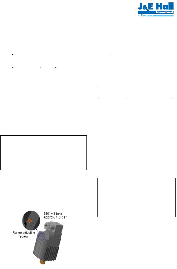
3.8 Fan speed controller setting
The fan speed controller controls the speed of the condenser.
It keeps the condensing pressure at a steady level by changing the speed of the fan according to the required condensing pressure.
Setting point can be increased by turning the adjusting screw clockwise. Setting point can be decreased by turning the adjusting screw counter clockwise. Adjustment should be within the range indicated for the setting pointer. Factory setting is 19 bar.
Recommend setting for range setting pointer/ range adjusting screw as table below:
Refrigerant |
R404A |
R134a |
Setting (bar) |
19 |
10 |
The XGE fan speed controller is cut off mode setting initially.
3.9 Oil requirements
Medium temperature application
|
|
Oil |
|
Model |
Oil type |
Charge |
|
|
|
(L) |
|
JEHSCU0200M1 |
|
1.24 |
|
JEHSCU0200M3 |
|
1.24 |
|
JEHSCU0250M1 |
|
1.30 |
|
JEHSCU0250M3 |
|
1.36 |
|
JEHSCU0300M1 |
Polyester oil |
1.45 |
|
JEHSCU0300M3 |
1.45 |
||
(160PZ) |
|||
JEHSCU0350M3 |
1.48 |
||
|
|||
JEHSCU0400M3 |
|
1.36 |
|
JEHSCU0500M3 |
|
2.07 |
|
JEHSCU0600M3 |
|
1.89 |
|
JEHSCU0680M3 |
|
1.80 |
3.10 Commissioning of the Condensing Unit
Please make sure that all manual service valves are fully open when starting the system for the first time.
This includes external shut off valves as well as liquid receiver valve in the unit.
3.11 Compressor electrical wiring
Important Note
Compressor wiring for 3 phases modal shall be observed. Supply phase sequence L1, L2 and L3 will affect the compressor rotating direction and damage the compressor.
Service technician should be present at initial startup to verify that the supply power is properly phased and that compressor is rotating in the correct direction.
Verification of proper rotation direction is made by observing that suction pressure drops and discharge pressure rises when the compressor is energized. Reverse rotation of a scroll compressor also results in substantially reduced current draw. Suction temperature will be high, discharge temperature will be low and the compressor may be abnormal noisy.
XGE fan speed controller |
|
Rev 001/January 2010 |
4 |
All specifications are subjected to change by the manufacturer without prior notice. The English text is the |
|
original instruction. Other languages are the translations of the original instructions. |
|
 Loading...