


DAIKIN FXMQ30MVJU, FXMQ36MVJU, FXMQ48MVJU, FXSQ12MVJU, FXSQ30MVJU INSTALLATION MANUAL
...INSTALLATION MANUAL
 SYSTEM Inverter Air Conditioners
MODELS
Ceiling-mounted Duct type
FXMQ30MVJU
FXMQ36MVJU
FXMQ48MVJU
Ceiling-mounted Built-in type
FXSQ12MVJU FXSQ30MVJU
FXSQ18MVJU FXSQ36MVJU
FXSQ24MVJU FXSQ48MVJU
Read these instructions carefully before installation.
Keep this manual in a handy place for future reference.
This manual should be left with the equipment owner.

SAFETY CONSIDERATIONS 2
BEFORE INSTALLATION 3
SELECTING INSTALLATION SITE 4
PREPARATIONS BEFORE INSTALLATION 5
INDOOR UNIT INSTALLATION 5
REFRIGERANT PIPING WORK 6
DRAIN PIPING WORK 7
ELECTRIC WIRING WORK 7
WIRING EXAMPLE AND HOW TO SET THE REMOTE CONTROLLER 8
SELECTING INSTALLATION SITE 11 PREPARATIONS BEFORE INSTALLATION 11 INDOOR UNIT INSTALLATION 12 REFRIGERANT PIPING WORK 12
DRAIN PIPING WORK 14 ELECTRIC WIRING WORK 15
WIRING EXAMPLE AND HOW TO SET THE REMOTE CONTROLLER 16
FIELD SETTING 19 TEST OPERATION 19
1
VRV SYSTEM Inverter Air Conditioners |
Installation manual |
CONTENTS |
|
1. SAFETY CONSIDERATIONS ......................................... |
2 |
2. BEFORE INSTALLATION ............................................... |
3 |
FXMQ30/36/48MVJU |
|
3.SELECTING INSTALLATION SITE................................ |
4 |
4.PREPARATIONS BEFORE INSTALLATION................. |
5 |
5.INDOOR UNIT INSTALLATION ..................................... |
5 |
6.REFRIGERANT PIPING WORK .................................... |
6 |
7.DRAIN PIPING WORK................................................... |
7 |
8.ELECTRIC WIRING WORK ........................................... |
7 |
9.WIRING EXAMPLE AND HOW TO SET |
|
THE REMOTE CONTROLLER ...................................... |
8 |
FXSQ12/18/24/30/36/48MVJU |
|
3.SELECTING INSTALLATION SITE ............................. |
11 |
4.PREPARATIONS BEFORE INSTALLATION............... |
11 |
5.INDOOR UNIT INSTALLATION ................................... |
12 |
6.REFRIGERANT PIPING WORK .................................. |
12 |
7.DRAIN PIPING WORK................................................. |
14 |
8.ELECTRIC WIRING WORK ......................................... |
15 |
9.WIRING EXAMPLE AND HOW TO SET |
|
THE REMOTE CONTROLLER .................................... |
16 |
COMMON ITEM |
|
10. FIELD SETTING............................................................ |
19 |
11. TEST OPERATION ....................................................... |
19 |
1.SAFETY CONSIDERATIONS
Please read these “SAFETY CONSIDERATIONS” carefully before installing air conditioning equipment and be sure to install it correctly. After completing the installation, make sure that the unit operates properly during the start-up operation. Please instruct the customer on how to operate the unit and keep it maintained.
Also, inform customers that they should store this installation manual along with the operation manual for future reference. This air conditioner comes under the term “appliances not accessible to the general public”.
Meaning of warning, caution and note symbols.
WARNING ............ |
Indication a potentially hazardous sit- |
|
uation which, if not avoided, could |
|
result in death or serious injury. |
CAUTION ............. |
Indication a potentially hazardous sit- |
|
uation which, if not avoided, may |
|
result in minor or moderate injury. It |
|
may also be sued to alert against |
|
unsafe practices. |
NOTE .................... |
Indication situation that may result in |
|
equipment or property-damage-only |
|
accidents. |
 WARNING
•Ask your dealer or qualified personnel to carry out installation work. Do not try to install the machine by yourself.
Improper installation may result in water leakage, electric shocks or fire.
•Perform installation work in accordance with this installation manual.
Improper installation may result in water leakage, electric shocks or fire.
•When installing the unit in a small room, take measures against to keep refrigerant concentration from exceeding allowable safety limits in the event of refrigerant leakage.
Contact the place of purchase for more information. Excessive refrigerant in a closed ambient can lead to oxygen deficiency.
•Be sure to use only the specified accessories and parts for installation work.
Failure to use the specified parts may result in water leakage, electric shocks, fire or the unit falling.
•Install the air conditioner on a foundation strong enough to withstand the weight of the unit.
A foundation of insufficient strength may result in the equipment falling and causing injuries.
•Carry out the specified installation work after taking into account strong winds, typhoons or earthquakes.
Improper installation work may result in the equipment falling and causing accidents.
•Make sure that a separate power supply circuit is provided for this unit and that all electrical work is carried out by qualified personnel according to local laws and regulations and this installation manual.
An insufficient power supply capacity or improper electrical construction may lead to electric shocks or fire.
•Make sure that all wiring is secured, the specified wires and used, and no external forces act on the terminal connections or wires.
Improper connections or installation may result in fire.
•When wiring the power supply and connecting the remote controller wiring and transmission wiring, position the wires so that the electric parts box lid can be securely fastened.
Improper positioning of the electric parts box lid may result in electric shocks, fire or the terminals overheating.
•If the refrigerant gas leaks during installation, ventilate the area immediately.
Toxic gas may be produced if the refrigerant gas comes into contact with fire.
•After completing the installation work, check that the refrigerant gas does not leak.
Toxic gas may be produced if the refrigerant gas leaks into the room and comes into contact with a source of fire, such as a fan heater, stove or cooker.
•Before touching electrical parts, turn off the unit.
•Ground the air conditioner. Do not connect the ground wire to gas or water pipes, lightning rod or a telephone ground wire.
Incomplete grounding may result in electric shocks.
•Do not touch the switch with wet fingers.
Touching a switch with wet fingers can cause electric shock.
•Install an leak circuit breaker, as required.
If an leak circuit breaker is not installed, electric shock may result.
2
•Do not install the air conditioner in the following locations:
(a)where a mineral oil mist or an oil spray or vapor is produced, for example in a kitchen Plastic parts may deteriorate and fall off or result in water leakage.
(b)where corrosive gas, such as sulfurous acid gas, is produced Corroding copper pipes or soldered parts may result in refrigerant leakage.
(c)near machinery emitting electromagnetic waves Electromagnetic waves may disturb the operation of the control system and result in a malfunction of the equipment.
(d)where flammable gases may leak, where there are carbon fiber or ignitable dust suspensions in the air, or where volatile flammables such as thinner or gasoline are handled. Operating the unit in such conditions may result in fire.
CAUTION
•While following the instructions in this installation manual, install drain piping in order to ensure proper drainage and insulate piping in order to prevent condensation.
Improper drain piping may result in water leakage and property damage.
•Do not touch the heat exchanger fins.
Improper handling may result in injury.
•Be very careful about product transportation.
Some products use PP bands for packaging. Do not use any PP bands for a means of transportation. It is dangerous.
•Safely dispose of the packing materials.
Packing materials, such as nails and other metal or wooden parts, may cause stabs or other injuries.
Tear apart and throw away plastic packaging bags so that children will not play with them. If children play with a plastic bag which was not torn apart, they face the risk of suffocation.
•Do not turn off the power immediately after stopping operation.
Always wait at least five minutes before turning off the power. Otherwise, water leakage and trouble may occur.
 NOTE
NOTE
•Install the indoor and outdoor units, power supply wiring and connecting wires at least 3.5ft. away from televisions or radios in order to prevent image interference or noise.
(Depending on the radio waves, a distance of 3.5ft. may not be sufficient enough to eliminate the noise.)
•Remote controller (wireless kit) transmitting distance can result shorter than expected in rooms with electronic fluorescent lamps. (inverter or rapid start types)
Install the indoor unit as far away from fluorescent lamps as possible.
•This unit is a class A product.
In a domestic environment this product may cause radio interference in which case the user may be required to take adequate measures.
•Dismantling of the unit, treatment of the refrigerant, oil and eventual other parts, should be done in accordance with the relevant local and national regulations.
2.BEFORE INSTALLATION
•When moving the unit while removing it from the carton box, be sure to lift it by holding on to the four lifting lugs without exerting any pressure on other parts, especially, the refrigerant piping, drain piping, and other resin parts.
•Be sure to check the type of R410A refrigerant to be used before installing the unit. (Using an incorrect refrigerant will prevent normal operation of the unit.)
•The accessories needed for installation must be retained in your custody until the installation work is completed. Do not discard them!
•Decide upon a line of transport.
•Leave the unit inside its packaging while moving, until reaching the installation site. Where unpacking is unavoidable, use a sling of soft material or protective plates together with a rope when lifting, to avoid damage or scratches to the unit.
•When moving the unit at or affter opening, hold the unit by the hanger brackets (× 4). Do not apply force to the refrigerant piping, drain piping or plastic parts.
•For the installation of an outdoor unit, refer to the installation manual attached to the outdoor unit.
•Do not install or operate the unit in rooms mentioned below.
•Laden with mineral oil, or filled with oil vapor or spray like in kitchens. (Plastic parts may deteriorate which could eventually cause the unit to fall out of place, or could lead to leaks.)
•Where corrosive gas like sulfurous gas exists. (Copper tubing and brazed spots may corrode which could eventually lead to refrigerant leaks.)
•Where exposed to combustible gases and where volatile flammable gas like thinner or gasoline is used. (Gas in the vicinity of the unit could ignite.)
•Where machines can generate electromagnetic waves. (Control system may malfunction.)
•Where the air contains high levels of salt such as that near the ocean and where voltage fluctuates greatly such as that in factories.
Also in vehicles or vessels.
•This unit, both indoor and outdoor, is suitable for installation in a commercial and light industrial environment.
If installed as a household appliance it could cause electromagnetic interference.
 NOTE
NOTE
•Be sure to read this manual before installing the indoor unit.
•Entrust installation to the place of purchase or a qualified serviceman. Improper installation could lead to leaks and, in worse cases, electric shock of fire.
•Use only parts provided with the unit or parts satisfying required specifications. Unspecified parts could cause the unit to fall out of place, or could lead to leaks and, in worse cases, electric shock or fire.
•Be sure to mount an air filter (part to be procured in the field) in the suction air passage in order to prevent water leaking, etc.
3

FXMQ30MVJU FXMQ48MVJU
FXMQ36MVJU
2-1 ACCESSORIES
Check the following accessories are included with your unit.
|
Name |
|
Metal |
|
Drain |
Insulation for |
|
|
Sealing pad |
|
|
clamp |
|
hose |
fitting |
|
|
||
|
|
|
|
|
|
|
|||
|
Quantity |
|
1 pc. |
|
1 pc. |
1 each. |
|
|
1 each. |
|
Shape |
|
|
|
|
for gas pipe |
|
|
Large |
|
|
|
|
|
|
for liquid pipe |
|
|
Mid |
|
|
|
|
|
|
|
|
|
|
|
Name |
|
Clamp |
|
Screws for duct flanges |
|
(Other) |
||
|
|
|
|
||||||
|
Quantity |
|
6 pcs. |
|
As described in table below |
|
|||
|
|
|
|
• Operation |
|||||
|
|
|
|
|
|
|
|
|
|
|
|
|
|
|
|
|
|
|
manual |
|
|
|
|
|
|
|
|
|
• Installation |
|
|
|
|
|
|
|
|
|
manual |
|
Shape |
|
|
|
|
|
|
|
• Washers |
|
|
|
|
|
|
|
|
|
for hanger |
|
|
|
|
|
|
|
|
|
bracket |
|
|
|
|
|
|
|
|
|
(8 pcs.) |
|
|
|
|
|
|
|
|
||
2-2 OPTIONAL ACCESSORIES |
|
|
|||||||
Table 1 |
|
|
|
|
|
|
|
|
|
|
|
|
|
|
Remote controller |
|
|
||
|
|
|
|
|
|
|
|||
|
Wired type |
|
|
|
|
BRC1C71 |
|||
|
|
|
|
|
|
|
|
|
|
FOR THE FOLLOWING ITEMS, TAKE SPECIAL CARE DURING CONSTRUCTION AND CHECK AFTER INSTALLATION IS FINISHED.
a. Items to be checked after completion of work
Items to be checked
Are the indoor and outdoor unit fixed firmly?
Is the gas leak test finished?
Is the unit fully insulated? Does drainage flow smoothly?
Does the power supply voltage correspond to that shown on the name plate?
Are wiring and piping correct?
Is the unit safely grounded?
Is wiring size according to specifications?
Is something blocking the air outlet or inlet of either the indoor or outdoor units?
Are refrigerant piping length and additional refrigerant charge noted down?
If not properly done, what is |
Check |
|
likely to occur. |
||
|
||
The units may drop, vibrate or |
|
|
make noise. |
|
|
It may result in insuffcient cool- |
|
|
ing. |
|
|
Condensate water may drip. |
|
|
Condensate water may drip. |
|
|
The unit may malfunction or |
|
|
the components burn out. |
|
|
The unit may malfunction or |
|
|
the components burn out. |
|
|
Dangerous at electric leakage. |
|
|
The unit may malfunction or |
|
|
the components burn out. |
|
|
It may result in insufficient cool- |
|
|
ing. |
|
|
The refrigerant charge in the |
|
|
system is not clear. |
|
|
|
|
b.Items to be checked at time of delivery
Also review the “SAFETY CONSIDERATIONS”
Items to be checked |
Check |
Did you explain about operations while showing the operation |
|
manual to your customer? |
|
Did you hand the operation manual over to your customer? |
|
|
|
c. Points for explanation about operations
The items with  WARNING and
  CAUTION marks in the operation manual are the items pertaining to possibillties for bodily injury and material damage in addition to the general usage of the product. Accordingly, it is necessary that you make a full explanation about the described contents and also ask your customers to read the operation manual.
2-3 NOTE TO INSTALLER
•Be sure to instruct customers how to properly operate the unit (especially cleaning filters, operating different functions, and adjusting the temperature) by having them carry out operations themselves while looking at the manual.
3.SELECTING INSTALLATION SITE
Please attach additional thermal insulation material to the unit body when it is believed that the relative humidity in the ceiling exceeds 80%. Use glass wool, polyethylene foam, or similar with a thickness of 3/8”. or more as thermal insulation material.
(1)Select an installation site where the following conditions are fulfilled and that meets with your customer’s approval.
•In the upper space (including the back of the ceiling) of the indoor unit where there is no possible dripping of water from the refrigerant pipe, drain pipe, water pipe, etc.
•Where optimum air distribution can be ensured.
•Where nothing blocks the air passage.
•Where condensate can be properly drained.
•If supporting structural members are not strong enough to take the unit’s weight, the unit could fall out of place and cause serious injury.
•Where the false ceiling is not noticeably on an incline.
•Where there is no risk of flammable gas leakage.
•Where sufficient clearance for maintenance and service can be ensured. (Refer to Fig. 1)
•Where piping between indoor and outdoor units is possible within the allowable limit. (Refer to the installation manual of the outdoor unit.)
 NOTE
NOTE
•Install the indoor and outdoor units, power supply wiring and connecting wires at least 3.5ft. away from televisions or radios in order to prevent image interference or noise. (Depending on the radio waves, a distance of 3.5ft. may not be sufficient enough to eliminate the noise.)
4

(2)Use suspension bolts for installation. Check whether the ceiling is strong enough to support the weight of the unit or not. If there is a risk, reinforce the ceiling before installing the unit.
4.PREPARATIONS BEFORE INSTALLATION
(1)Relative positions of indoor unit and suspension bolt.
(Refer to Fig. 2)
(2)Install a canvass duct to the air discharge outlet and air inlet so that vibration from the machine body isn’t transmitted to the duct or ceiling.
You should also apply acoustic (insulation material) to the inside of the duct, and vibration insulation rubber to the suspension bolts.
(3)Install suspension bolts. (Use bolts of 3/8” diameter.)
•Install the equipment where supporting structures are strong enough to bear the equipment’s weight. Use embedded inserts or anchor bolts with new buildings and hole-in-anchors with old buildings.
5.INDOOR UNIT INSTALLATION
Installing optional accessories before installing the indoor unit is easier.
As for the parts to be used for installation work, be sure to use the provided accessories and specified parts designated by our company.
(1)Fix the hanger bracket to the suspension bolt. Tighten both upper and lower nuts firmly using washers.
(2)Adjust the height of the unit.
(3)Make sure the unit is level.
•Level the unit with a level when installing. If the unit is not level, it could become the source of water leaks.
•When leveling the unit, check all four corners with a level or a vinyl tube containing water. (See the figure on the right.)
(4)Tighten the nuts on the top.
 NOTE
NOTE
Setting the unit at an angle opposite to the drain piping might cause leaks.
5
6.REFRIGERANT PIPING WORK
6-1 GENERAL INSTRUCTIONS
•For refrigerant piping of outdoor units, see the installation manual attached to the outdoor unit.
•Before refrigerant piping work, check which type of refrigerant is used. Proper operation is not possible if the types of refrigerant are not the same.
•The outdoor unit is charged with refrigerant.
 NOTE
NOTE
•Use a pipe cutter and flare suitable for the type of refrigerant.
•To prevent dust, moisuture or other foreign matter from infiltrating the tube, either pinch the end or cover it with tape.
•Do not allow anything other than the designated refrigerant to get mixed into the refrigerant circuit, such as air, etc. If any refrigerant gas leaks while working on the unit, ventilate the room thoroughly right away.
6-2 Connecting the refrigerant piping
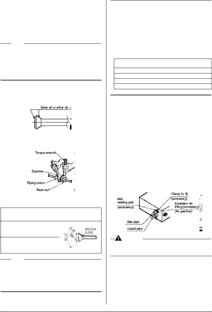
•When connecting the flare nut, coat the flare both inside and outside with ester oil or ether oil and initially tighten by hand 3 or 4 turns before tightening firmly.
•To prevent flare nut cracking and gas leaks, be sure to use both a spanner and torque wrench together, as shown in the drawing below, when connecting or disconnecting pipes to/ from the unit.
•Refer to the Table 2 for the dimensions of flare nut spaces.
•Refer to the Table 2 to determine the proper tightening torque. Table 2
Pipe |
Tightening torque |
Flare |
|
|
dimensions |
Flare shape (in.) |
|||
size |
(ft.lbf) |
|||
A (in.) |
|
|||
|
|
|
||
φ 1/4” |
10.4 – 12.7 |
0.342-0.358 |
|
|
φ 3/8” |
24.1 – 29.4 |
0.504-0.520 |
|
|
φ 1/2” |
36.5 – 44.5 |
0.638-0.654 |
|
|
φ 5/8” |
45.6 – 55.6 |
0.760-0.776 |
|
|
|
|
|
|
 NOTE
NOTE
•Apply ester oil or ether oil around the flare portions before connecting.
•The flare nuts used must be those included with the main body.
•Over-tightening may damage the flare and cause a refrigerant leakage.
Not recommendable but in case of emergency
You must use a torque wrench but if you are obliged to install the unit without a torque wrench, you may follow the installation method mentioned below.
After the work is finished, make sure to check that there is no gas leak.
When you keep on tightening the flare nut with a spanner, there is a point where the tightening torque
suddenly increases. From that position, further tighten the flare nut the angle shown below:
Table 3
Pipe size |
Further tightening |
Recommended arm length of |
|
angle |
tool (in.) |
||
|
|||
φ 1/4” |
60 to 90 degrees |
Approx. 5 7/8 |
|
φ 3/8” |
60 to 90 degrees |
Approx. 7 7/8 |
|
φ 1/2” |
30 to 60 degrees |
Approx. 9 13/16 |
|
φ 5/8” |
30 to 60 degrees |
Approx. 11 13/16 |
|
|
|
|
6-3 Piping insulation
•Execute heat insulation work completely on both sides of the gas piping and the liquid piping. Otherwise, a water leakage can result sometimes.
•When using a heat pump, the temperature of the gas piping can reach up to approximately 250°F, so use insulation which is sufficiently resistant.
•Also, in cases where the temperature and humidity of the refrigerant piping sections might exceed 86°F or RH80%, reinforce the refrigerant insulation. (13/16” or thicker) Condensation may form on the surface of the insulating material.
•Check the pipe connector for gas leaks, then insulate it as shown in the drawing below.
•Make absolutely sure to execute heat insulation works on the pipe-connecting section after checking gas leakage by thoroughly studying the following figure and using the attached heat insulating materials for fitting. (Fasten both ends with the clamps (accessory).)
•Wrap the sealing pad (accessory) only around the insulation for the joints on the gas piping side.
CAUTION
Be sure to insulate any field piping all the way to the piping connection inside the unit. Any exposed piping may cause condensation or burns if touched.
6
 Loading...