Daikin RQYQ8PY1, RQYQ10PY1, RQYQ12PY1, RQYQ14PY1, RQYQ16PY1 Installation manuals
...
INSTALLATION MANUAL (1)


 System air conditioner “Ve-upQ” Series
MODELS
RQYQ8PY1
RQYQ10PY1
RQYQ12PY1
RQYQ14PY1
RQYQ16PY1
RQYQ18PY1
RQYQ20PY1
RQYQ22PY1
RQYQ24PY1
RQYQ26PY1
RQYQ28PY1
RQYQ30PY1
RQYQ32PY1
RQYQ34PY1
RQYQ36PY1
RQYQ38PY1
RQYQ40PY1
RQYQ42PY1
RQYQ44PY1
RQYQ46PY1
RQYQ48PY1

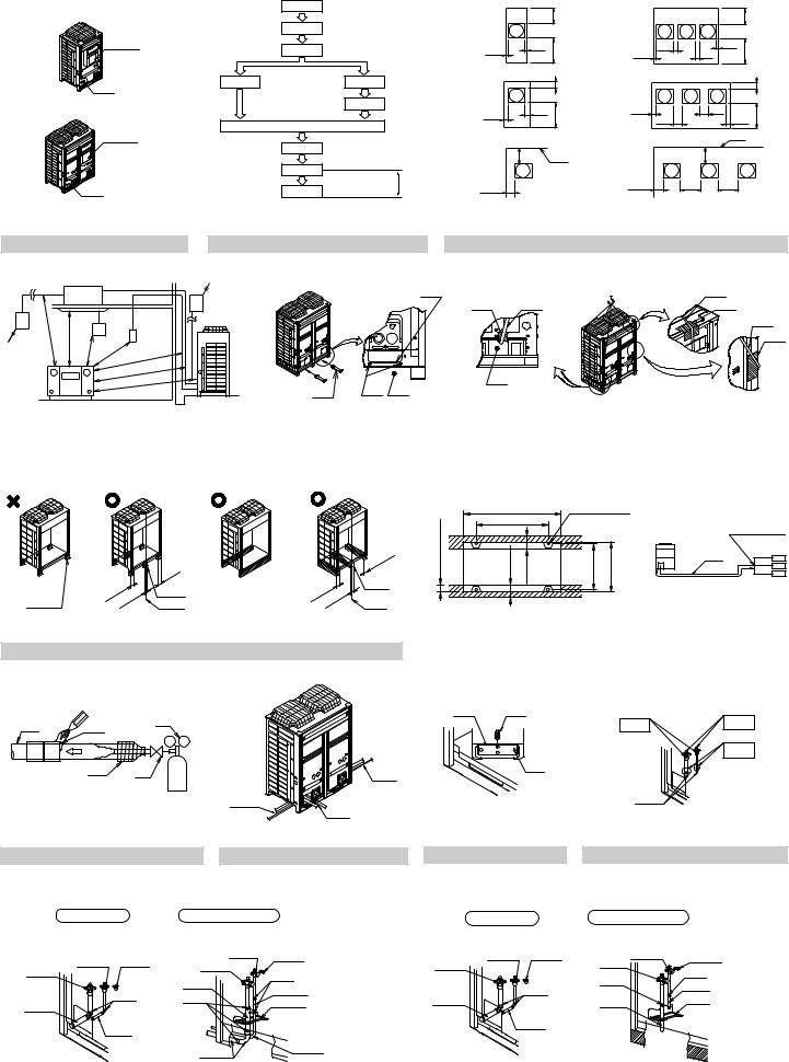
[Q8 · 10 · 12 type] |
1 |
|
< If installed as a single unit > |
< When installed in serial > |
|
||||||||
|
(Pattern 1) |
|
|
≥300 |
(Pattern 1) |
|
|
|
≥300 |
||||
|
|
|
|
|
|
|
|
||||||
|
2 |
|
|
|
|
4 |
|
|
|
|
|
4 |
|
|
|
|
|
|
|
|
|
|
|
|
|
|
|
1, 2, 3 |
3 |
|
≥10 |
1 |
≥10 |
≥500 |
≥20 |
1 |
≥20 |
≥10 |
≥500 |
||
|
|
|
|
≥10 |
|
|
|||||||
|
|
|
|
|
|
3 |
|
|
|
|
|
3 |
|
4 |
5 |
4 |
(Pattern 2) |
|
|
≥100 |
(Pattern 2) |
|
|
|
|
≥ |
100 |
|
|
6 |
|
|
|
4 |
|
|
|
|
|
|
4 |
[Q14 · 16 type] |
|
≥50 |
1 |
≥50 |
≥500 |
≥50 |
1 |
≥100 |
|
|
|
||
|
|
|
≥500 |
||||||||||
|
7 |
|
|
|
≥100 |
|
|
≥50 |
|||||
1, 2, 3 |
|
|
|
|
3 |
|
|
|
2 |
|
|
3 |
|
|
|
|
|
|
|
|
|
|
|
|
|
||
|
8 |
|
(Pattern 3) |
|
≥300 2 |
(Pattern 3) |
|
≥300 |
|
|
|
||
|
|
|
|
|
|
|
|
|
|
||||
|
9 |
|
|
|
|
|
|
|
|
|
|
|
|
4 |
10 |
11 |
≥200 |
|
1 |
|
≥200 |
≥400 |
1 |
≥400 |
|
|
|
|
|
|
|
|
|
|
|
|
|
|
|
||
|
|
|
|
|
|
|
|
|
|
|
|
|
|
figure 1 |
figure 2 |
|
figure 3 |
|
|
|
|
|
|
|
|
|
|
2
1500 |
<![if ! IE]> <![endif]>1000 |
≥ |
<![if ! IE]> <![endif]>≥ |
|
5
1 |
|
|
|
4 |
|
|
1 |
|
|
|
|
|
|
||
|
|
2 |
|
|
2 |
1 |
2 |
|
3 |
|
|
|
|
|
1 |
1000 |
4 |
|
|
|
|
2 |
|
≥ |
|
|
|
|
|||
≥ |
1000 |
≥1500 |
|
|
|
|
|
|
|
|
|
|
|
||
|
|
|
|
|
|
|
|
|
|
≥1500 |
|
|
|
3 |
|
|
|
≥1500 |
2 |
3 |
|
|
|
|
|
1 |
|
|
|
||
|
|
(mm) |
|
|
|
|
|
figure 4 |
|
figure 5 |
|
figure 6 |
1
figure 7
≥100 ≥100
≥100
2
3
≥100  ≥100
≥100


 ≥100
≥100
2
3
|
|
A |
|
1 |
|
|
|
|
B |
|
|
|
4 |
|
|
|
|
|
1 |
|
| <![if ! IE]> <![endif]>) |
|
|
|
|
|
|
| <![if ! IE]> <![endif]>3 |
|
|
|
|
|
5 |
| <![if ! IE]> <![endif]>66( |
<![if ! IE]> <![endif]>66≥ |
<![if ! IE]> <![endif]>66≥ |
<![if ! IE]> <![endif]>737-722 |
<![if ! IE]> <![endif]>765 |
3 |
|
|
|
|
|
|
2 |
|
|
|
|
|
|
2 |
|
figure 8 |
|
figure 9 |
|
|
|
6 |
|
1 |
2 |
1 |
2 |
1 |
2 |
|
|
|
|
4 |
5 |
|
|
|
|
|
|
||||
|
3 |
|
|
|
|
|
|
6 |
|
4 |
5 |
3 |
|
3 |
3 |
|
|
|
|
|
|
|
||||
|
|
|
1 |
|
|
|
3 |
|
|
|
|
|
|
2 |
|
|
|
figure 10 |
|
|
figure 11 |
|
figure 12 |
|
figure 13 |
|
|
1 |
|
2 |
|
1 |
|
2 |
|
|
3 |
|
4 |
|
3 |
|
4 |
|
|
6 |
7 |
6 |
7 |
6 |
7 |
6 |
7 |
5 |
5 |
8 |
5 |
|
5 |
8 |
||
|
|
11 |
|
|
8 |
|||
|
|
|
|
|
12 |
|||
|
|
|
12 |
|
8 |
|||
|
|
8 |
|
|
||||
|
|
8 |
10 |
11 |
13 |
|||
10 |
|
13 |
|
|||||
|
|
|
14 |
|
|
|
14 |
|
|
|
|
|
|
|
|
||
|
|
|
|
|
9 |
|
|
|
|
|
9 |
|
|
|
|
|
|
|
|
|
|
|
|
|
|
|
|
|
|
15 |
|
16 |
|
|
|
|
|
|
|
|
|
|
|
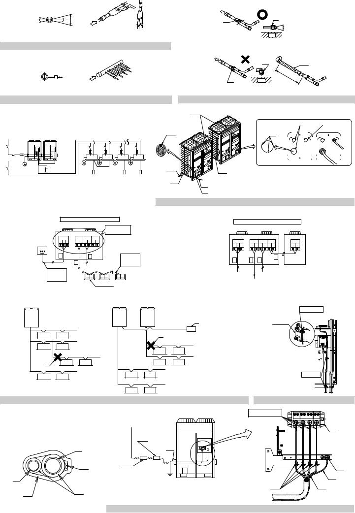
figure 14 |
|
figure 15 |

|
|
|
|
|
18-1 |
|
|
|
|
C |
2 |
1 |
|
1 |
2 |
|
1 |
|
||
|
|
|
|
|
||
A-arrow view |
A |
3 |
4 |
|
3 |
|
|
|
4 |
|
|||
|
|
|
|
|
|
|
figure 16 |
|
|
|
|
(C-arrow view) |
|
|
|
|
|
|
|
|
|
|
|
D |
|
|
|
|
|
|
|
|
1 |
5 |
1 |
|
|
|
|
6 |
|
B |
|
1 |
|
4 |
|
|
|
|
|
|
|||
B-arrow view |
|
18-2 |
(D-arrow view) |
18-3 |
||
|
|
|||||
figure 17 |
|
|
figure 18 |
|
|
|
|
|
|
|
1 |
|
|
|
|
2 |
1 |
|
5 |
9 |
11 |
|
10 |
|
||
|
2 |
4 |
3 |
|
|
|
4 |
|
|
1 |
|
3 |
|
|
|
2 |
6 |
8 |
3 |
|
|
7 |
||
|
|
|
8 |
4 |
|
|
|
7 |
5 |
|
|
|
|
|
|
|
|
|
6 |
12 |
12 |
|
|
|
||||||||||
|
8 |
|
|
13 |
|
|
|
|||||||
|
|
|
|
|
|
|
|
|
|
|
|
|
|
|
|
|
|
|
|
|
|
|
|
|
|
|
|
|
|
|
|
|
|
|
|
|
|
|
|
|
|
|
|
|
|
|
|
|
|
|
|
|
|
|
|
|
|
|
|
|
|
|
|
|
|
|
|
|
|
|
|
|
|
|
|
|
|
|
|
|
|
|
|
|
|
|
|
|
|
figure 19 |
|
figure 20 |
|
|
|
1 |
|
|
|
|
|
|
2 |
|
|
8 |
|
ABC I/P |
A1P |
|
|
||
|
|
|
|
|||
|
|
|
TOIN/DUNIT TOOUT/DUNIT |
TOMULTIUNIT |
|
|
3 |
A |
B C |
F1 F2 F1 F2 Q1 Q2 |
|
|
|
|
|
|
|
|
|
|
ABC |
|
|
|
|
|
|
|
3 |
|
1 |
|
|
6 |
|
|
|
1 |
|
|
|
|
|
|
|
|
|
|
|
|
|
4 |
|
|
|
|
5 |
|
F1 F2 |
F1 F2 |
F1 F2 |
|
|
|
|
|
|
7 |
|
1
2 |
3 |
ABC I/P |
A1P |
|
|
A1P |
|
TO IN/D UNIT TOOUT/DUNIT TOMULTIUNIT |
TOMULTIUNIT |
||
A B C |
F1 F2 F1 F2 Q1 Q2 |
Q1 Q2 |
||
3 |
1 |
1 |
2 |
|
|
|
|||
4 |
|
|
6 |
|
|
5 |
|
|
|
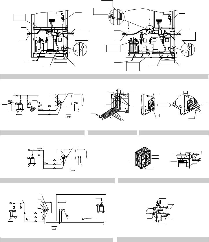
figure 21 |
|
figure 22 |
|
1 |
|
1 |
|
1 |
|
|
2 |
|
|
|
|
|
1 |
|||
|
|
|
|
|
|
7 |
ABC I/P |
|
|
|
|
|
|
|
(A1P) |
||
|
|
|
3 |
10 |
|
|
|
|
9 |
2 |
2 |
9 |
5 |
|
|
|
|
|
|
|
|
|||||
|
|
|
4 |
|
|
|
|
|
|
2 |
2 |
|
|
2 |
2 |
|
|
|
|
|
|
|
|
|
||
|
|
|
|
|
|
4 |
|
|
|
5 |
2 |
2 |
|
2 |
2 |
|
|
|
|
6 |
|
8 |
2 |
2 |
2 |
2 |
2 |
|
|
|
||
|
|
2 |
2 |
6 |
|
|
|
||
figure 23 |
|
|
|
figure 24 |
|
|
5 |
|
|
|
|
|
L1 |
L2 |
L3 |
N |
|
|
1 |
|
|
6 |
|
|
|
|
|
|
|
|
3 |
|
|
|
|
2 |
4 |
|
|
|
|
|
2 |
|
|
|
|
|
3 |
|
|
7 |
|
|
|
|
|
|
1 |
|
|
|
|
4 |
|
|
|
|
|
|
|
4 |
8 |
|
|
8 |
5 |
|
|
|
|
|
|
|
|
|
|
figure 25 |
|
figure 26 |

|
|
[In case of Q8 · 10 · 12 type] |
|
1 |
|
|
[In case of Q14 · 16 type] |
|
|
||
|
|
|
|
|
|
|
|
||||
|
|
|
|
|
11 |
13 |
|
|
|
|
11 |
|
1 |
|
10 |
|
|
|
|
|
10 |
|
|
|
|
2 |
12 |
|
9 |
|
|
|
12 |
|
9 |
|
|
|
|
|
|
|
2 |
|
|
||
|
|
|
|
|
|
|
|
|
|
|
|
|
|
3 |
|
|
8 |
|
|
3 |
|
|
8 |
|
|
|
|
|
|
|
|
|
|
||
|
|
|
|
|
|
|
|
|
|
|
|
|
|
|
|
|
|
|
|
15 |
|
|
|
|
|
4 |
|
6 |
|
|
|
4 |
6 |
|
|
|
|
5 |
|
7 |
|
|
|
7 |
|||
|
|
|
|
|
|
14 |
5 |
|
|||
|
|
|
|
|
|
|
|
|
|
|
|
figure 27 |
|
|
|
|
|
|
|
|
|
|
|
|
|
|
7 |
|
14 |
|
1 |
6 |
1 |
|
3 |
|
|
|
|
|
|
|
|||||
|
|
|
8 |
13 |
13 |
|
|
|
|
|
|
|
|
6 |
|
|
|
|
|
|
|
||
|
|
9 |
|
|
|
|
|
|
|
4 |
|
1 |
|
|
10 |
|
|
2 |
|
5 |
|
|
|
2 |
3 |
|
|
|
|
|
|
|
|
||
|
11 |
|
15 |
|
|
|
|
|
|
||
|
|
|
|
|
|
|
|
|
|
||
|
|
5 |
12 |
|
3 |
|
|
|
|
|
|
|
4 |
|
: 16 |
|
4 |
2 |
|
|
|||
|
|
|
|
|
: 17 |
|
|
|
5 |
||
|
|
|
|
|
|
|
|
|
|
||
|
|
|
|
|
|
|
|
|
|
|
|
figure 28 |
|
|
|
|
figure 29 |
|
|
figure 30 |
|
|
|
|
|
3 |
4 |
|
11 |
|
|
|
|
1 |
7 |
|
|
|
10 |
10 |
|
|
|
|
|||
|
|
|
5 |
|
|
|
|
||||
|
|
|
|
|
|
3 |
5 |
|
|||
|
|
|
6 |
|
|
|
|
|
|
||
|
|
|
7 |
|
|
|
|
1 |
4 |
6 |
|
|
|
1 |
|
|
|
|
|
|
|||
|
|
8 |
|
|
|
|
|
3 |
|||
|
|
|
|
|
12 |
|
|
|
|
||
|
|
2 |
9 |
|
|
|
|
|
|
|
|
|
|
|
13 |
|
|
|
2 |
|
|
||
|
|
|
|
|
|
|
|
|
|
||
|
|
|
|
|
14 |
|
|
|
|
|
|
figure 31 |
|
|
|
figure 32 |
|
|
11 |
|
15 |
|
|
3 |
4 |
|
|
1 |
|
|
|
|
|
||
|
5 |
10 |
10 |
|
2 |
|
6 |
|
|
||
|
|
|
|
|
|
|
7 |
|
|
|
|
1 |
8 |
|
9 |
5 |
|
|
|
3 |
|||
2 |
9 |
|
|||
|
|
|
|||
|
|
|
|
||
|
|
|
|
4 |
|
|
|
|
14 |
|
|
|
|
|
: 12 |
|
|
|
|
|
: 13 |
|
|
figure 33 |
|
|
|
figure 34 |
|

RQYQ8PY1 |
RQYQ18PY1 |
RQYQ28PY1 |
RQYQ38PY1 |
RQYQ48PY1 |
Installation |
RQYQ10PY1 |
RQYQ20PY1 |
RQYQ30PY1 |
RQYQ40PY1 |
VRVIII System air conditioner |
|
|
|
||||
RQYQ12PY1 |
RQYQ22PY1 |
RQYQ32PY1 |
RQYQ42PY1 |
“Ve-upQ” Series |
manual |
RQYQ14PY1 |
RQYQ24PY1 |
RQYQ34PY1 |
RQYQ44PY1 |
||
RQYQ16PY1 |
RQYQ26PY1 |
RQYQ36PY1 |
RQYQ46PY1 |
|
|
|
|
|
|
|
|
|
|
|
|
Meaning of WARNING and CAUTION notices |
|
CONTENTS
1. |
FIRST OF ALL ......................................................................... |
1 |
|
|
1-1 |
Safety precautions .......................................................... |
1 |
|
1-2 |
Special notice of product ................................................. |
2 |
|
1-3 |
Disposal requirements ..................................................... |
2 |
2. |
INTRODUCTION...................................................................... |
2 |
|
|
2-1 |
Combination..................................................................... |
2 |
|
2-2 |
Standard supplied accessories........................................ |
3 |
|
2-3 |
Option accessory ............................................................. |
3 |
|
2-4 |
Technical and Electrical specifications ............................ |
3 |
|
2-5 |
Main components ............................................................ |
3 |
|
2-6 |
Installation Process.......................................................... |
3 |
3. |
SELECTION OF LOCATION ................................................... |
3 |
|
4. |
INSPECTING AND HANDLING THE UNIT ............................. |
4 |
|
5. |
PLACING THE UNIT................................................................ |
4 |
|
6. |
REFRIGERANT PIPING .......................................................... |
4 |
|
|
6-1 |
Selection of piping material and Refrigerant |
|
|
|
branching kit .................................................................... |
4 |
|
6-2 Protection against contamination when installing pipes ... |
5 |
|
|
6-3 |
Pipe connection ............................................................... |
5 |
|
6-4 |
Connecting the refrigerant piping..................................... |
5 |
7. |
FIELD WIRING ........................................................................ |
7 |
|
|
7-1 |
Power circuit, safety device, and cable requirements...... |
7 |
|
7-2 |
Wiring Connection Example for Whole System ............... |
7 |
|
7-3 |
Leading wire Procedure ................................................... |
7 |
|
7-4 |
Transmission Wiring Connection Procedure ................... |
8 |
|
7-5 |
Power Wiring Connection Procedure............................... |
8 |
|
7-6 |
Procedure for Wiring Inside Units .................................... |
9 |
8. |
AIR TIGHT TEST AND VACUUM DRYING ............................. |
9 |
|
|
8-1 |
Preparations .................................................................... |
9 |
|
8-2 |
Air tight test and vacuum drying method ......................... |
9 |
9. |
PIPE INSULATION ................................................................ |
10 |
|
10. |
CHECKING OF DEVICE AND INSTALLATION |
|
|
|
CONDITIONS ........................................................................ |
10 |
|
11. |
ADDITIONAL REFRIGERANT CHARGE AND |
|
|
|
CHECK OPERATION ............................................................ |
10 |
|
|
11-1 |
Before working............................................................... |
10 |
|
11-2 |
Procedure of Adding Refrigerant charging and check |
|
|
|
operation........................................................................ |
12 |
12. |
ONSITE SETTINGS............................................................... |
13 |
|
|
12-1 |
Onsite Settings With the Power Off ............................... |
13 |
|
12-2 |
Onsite Settings With the Power On ............................... |
13 |
13. |
TEST RUN ............................................................................. |
13 |
|
|
13-1 |
Before test run ............................................................... |
13 |
|
13-2 |
Test Run ........................................................................ |
13 |
|
13-3 |
Checks After Test Run................................................... |
13 |
14. |
CAUTION FOR REFRIGERANT LEAKS ............................... |
13 |
|
1.FIRST OF ALL
•This document is an installation manual for the Daikin “Ve-upQ” Series VRV Inverter. Before installing the unit, read this manual thoroughly, and following the instructions contained in it. After installation, do a test run to make sure the unit runs properly, and then explain how to operate and take care of the unit to the customer, using the operation manual.
•Lastly, make sure the customer keeps this manual, along with the operation manual, in a safe place.
•This manual does not describe how to install the indoor unit.
Refer to the installation manual included with the indoor unit for that.
1-1 Safety precautions
Please read these “Safety precautions” carefully before installing air conditioning unit and be sure to install it correctly.
After completing installation, conduct a trial operation to check for faults and explain to the customer how to operate the air conditioner and take care of it with the aid of the operation manual. Ask the customer to store the installation manual along with the operation manual for future reference.
This air conditioner comes under the term “appliances not accessible to the general public”.
WARNING..... Failure to follow these instructions properly may result in personal injury or loss of life.
CAUTION...... Failure to observe these instructions properly may result in property damage or personal injury, which may be serious depending on the circumstances.
WARNING
•Ask your dealer or qualified personnel to carry out installation work.
Do not attempt to install the air conditioner yourself. Improper installation may result in water leakage, electric shocks or fire.
•Install the air conditioner in accordance with the instructions in this installation manual.
Improper installation may result in water leakage, electric shocks or fire.
•When installing the unit in a small room, take measures against to keep refrigerant concentration from exceeding allowable safety limits in the event of refrigerant leakage.
Contact the place of purchase for more information. Excessive refrigerant in a closed ambient can lead to oxygen deficiency.
•Be sure to use only the specified accessories and parts for installation work.
Failure to use the specified parts may result in the unit falling, water leakage, electric shocks or fire.
•Install the air conditioner on a foundation strong enough to withstand the weight of the unit.
A foundation of insufficient strength may result in the equipment falling and causing injury.
•Carry out the specified installation work after taking into account strong winds, typhoons or earthquakes.
Failure to do so during installation work may result in the unit falling and causing accidents.
•Make sure that a separate power supply circuit is provided for this unit and that all electrical work is carried out by qualified personnel according to local laws and regulations and this installation manual. An insufficient power supply capacity or improper electrical construction may lead to electric shocks or fire.
•Make sure that all wiring is secured, the specified wires are used, and that there is no strain on the terminal connections or wires. Improper connections or securing of wires may result in abnormal heat build-up or fire.
•When wiring the power supply and connecting the remote controller wiring and transmission wiring, position the wires so that the EL.COMPO.BOX lid can be securely fastened.
Improper positioning of the EL.COMPO.BOX lid may result in electric shocks, fire or the terminals overheating.
•If refrigerant gas leaks during installation, ventilate the area immediately.
Toxic gas may be produced if the refrigerant comes into contact with fire.
•After completing installation, check for refrigerant gas leakage. Toxic gas may be produced if the refrigerant gas leaks into the room and comes into contact with a source of fire, such as a fan heater, stove or cooker.
•Do not directly touch refrigerant that has leaked from refrigerant pipes or other areas, as there is a danger of frostbite.
•Be sure to switch off the unit before touching any electrical parts.
•Do not allow children to climb on the outdoor unit and avoid placing objects on the unit.
Injury may result if the unit becomes loose and falls.
•Be sure to earth the air conditioner.
Do not earth the unit to a utility pipe, lightning conductor or telephone earth lead. Imperfect earthing may result in electric shocks or fire.
A high surge current from lightning or other sources may cause damage to the air conditioner.
•Be sure to install an earth leakage breaker.
Failure to install an earth leakage breaker may result in electric shocks or fire.
CAUTION
•While following the instructions in this installation manual, install drain piping to ensure proper drainage and insulate piping to prevent condensation.
Improper drain piping may result in indoor water leakage and property damage.
1 |
English |
 Loading...