


REYQ8PY1B
REYQ10PY1B
REYQ12PY1B
REYQ14PY1B
REYQ16PY1B
INSTALLATION MANUAL


 System air conditioner
Installation manual
VRVIII System air conditioner English
Installationsanleitung Deutsch
VRVIII System Klimaanlage
Manuel d’installation Français
Conditionneur d’air VRVIII System
Manual de instalación Español
Sistema de acondicionador de aire VRVIII
Manuale di installazione Italiano
Condizionatore d’aria a sistema VRVIII
Εγχειρßδιο εγκατÜστασηò ΕλληνικÜ Κλιìατιστικü ìε σýστηìα VRVIII
Installatiehandleiding Nederlands
Airconditioner met VRVIII Systeem
Manual de instalação Portugues
Ar condicionado VRVIII System
Рóêоводство по монтажó Рóссêий Кондиционер системы VRVIII
Montaj elkitabý Türkçe
VRVIII System Klima

DAIKIN INDUSTRIES, LTD.
RXYQ5PY1(E), RXYQ8PY1(E), RXYQ10PY1(E), RXYQ12PY1(E), RXYQ14PY1(E), RXYQ16PY1(E), RXYQ18PY1(E), |
REYQ8PY1, REYQ10PY1, REYQ12PY1, REYQ14PY1, REYQ16PY1, |
RXYQ20PY1(E), RXYQ22PY1(E), RXYQ24PY1(E), RXYQ26PY1(E), RXYQ28PY1(E), |
REYQ18PY1, REYQ20PY1, REYQ22PY1, REYQ24PY1, REYQ26PY1, REYQ28PY1, REYQ30PY1, REYQ32PY1, |
RXYQ30PY1(E), RXYQ32PY1(E), RXYQ34PY1(E), RXYQ36PY1(E), RXYQ38PY1(E), |
REYQ34PY1, REYQ36PY1, REYQ38PY1, REYQ40PY1, REYQ42PY1, REYQ44PY1, REYQ46PY1, REYQ48PY1, |
RXYQ40PY1(E), RXYQ42PY1(E), RXYQ44PY1(E), RXYQ46PY1(E), RXYQ48PY1(E), |
REYQ8PY1B, REYQ10PY1B, REYQ12PY1B, REYQ14PY1B, REYQ16PY1B, |
RXYQ50PY1(E), RXYQ52PY1(E), RXYQ54PY1(E), |
REMQ8PY1, REMQ10PY1, REMQ12PY1, REMQ14PY1, REMQ16PY1, |
|
BSVQ100PV1, BSVQ160PV1, BSVQ250PV1, |
EN60335-2-40,
Low Voltage 2006/95/EC
Machinery Safety 98/37/EC
Electromagnetic Compatibility 89/336/EEC
DAIKIN.TCF.024
TNO
0510260101
<![endif]>1C-3P177868
Noboru Murata |
|
|
Manager Quality Control Department |
Umeda Center Bldg., 4-12, Nakazaki-Nishi 2-chome, |
|
1st of April 2007 |
||
Kita-ku, Osaka, 530-8323 Japan |
||
|
||
|
|
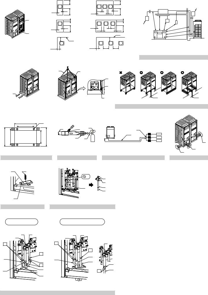
< If installed as a single unit > |
< When installed in serial > |
||||||||
(Pattern 1) |
|
|
≥300 |
(Pattern 1) |
|
|
|
≥300 |
|
|
|
|
4 |
|
|
|
|
|
4 |
≥10 |
1 |
≥10 |
≥500 |
≥20 |
1 |
≥20 |
≥10 |
≥500 |
|
|
|
≥10 |
|
|
|||||
|
|
|
3 |
|
|
|
|
|
3 |
1 |
|
|
≥100 |
(Pattern 2) |
|
|
|
|
≥100 |
(Pattern 2) |
|
|
|
|
|
|
|||
|
|
|
4 |
|
|
|
|
|
4 |
≥50 |
1 |
≥50 |
≥500 |
≥50 |
1 |
≥100 |
|
≥500 |
|
|
|
≥100 |
|
|
≥50 |
||||
2 |
|
|
3 |
|
|
|
2 |
|
3 |
|
|
|
|
|
|
|
|
|
|
(Pattern 3) |
|
≥300 2 |
(Pattern 3) |
|
≥300 |
|
|
||
|
|
|
|
|
|
||||
≥200 |
|
1 |
|
≥200 |
≥400 |
1 |
≥400 |
|
|
figure 1 |
|
figure 2 |
1 |
2 |
1 |
1
2
1
3
figure 4 |
|
figure 5 |
|
figure 6 |
1
2
2 |
1500 |
<![if ! IE]> <![endif]>1000 |
|
3 |
|
|
1000 |
4 |
|||
|
≥ |
<![if ! IE]> <![endif]>≥ |
≥ |
|
|
|
|
|
1000 |
|
|
|
|
|
≥ |
|
≥1500 |
|
|
|
|
|
≥1500 |
|
5 |
|
|
|
≥1500 |
|
|
|
|
|
(mm)
figure 3
2 |
3 |
|
4 |
|
≥100 |
|
100 |
|
|
≥ |
|
|
≥100 |
|
≥100 |
≥100 |
5 |
≥100 |
5 |
|
1300 |
1 |
|
|
|
1 |
|
|
1162 |
|
|
|
|
|
|
|
|
|
1 |
2 |
6 |
|
|
|
|
|
|
4 |
|
||
|
|
|
|
3 |
|
5 |
6 |
| <![if ! IE]> <![endif]>765 2 729 |
|
<![if ! IE]> <![endif]>631 3 765≥ |
<![if ! IE]> <![endif]>4 |
|
2 |
|
|
|
4 |
5 |
3 |
|
|||
|
|
|
|
|
|||
|
|
|
|
|
|
3 |
|
|
|
|
|
|
|
|
2 |
|
|
|
|
|
|
|
1 |
figure 7 |
|
|
|
figure 8 |
|
figure 9 |
figure 10 |
1 |
2 |
|
|
|
|
|
|
|
|
|
|
|
2 |
5 |
|
|
|
|
|
|
|
4 |
|
|
|
|
|
|
1 |
6 |
|
|
|
|
|
|
3 |
|
|
|
|
|
|
|
|
|
|
|
3 |
|
|
|
|
|
|
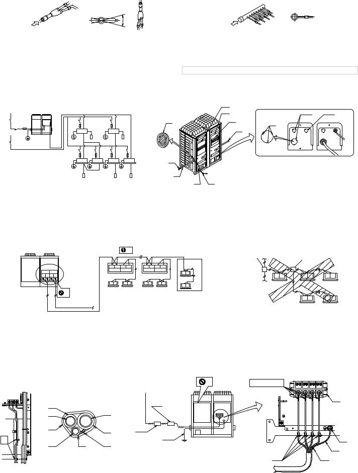
figure 11 |
|
|
|
figure 12 |
|
|
|
1 |
|
|
2 |
|
3 |
|
|
4 |
|
6 |
7 |
6 |
7 |
|
5 |
|
|||
|
5 |
17 |
||
8 |
|
8 |
6 |
|
|
|
|||
|
|
|
||
|
8 |
|
8 |
|
|
|
15 |
||
9 |
|
14 |
||
13 |
16 |
|||
|
|
|||
|
8 |
|
18 |
|
|
|
|
||
12 |
11 |
|
15 |
|
|
|
|
8 |
|
|
10 |
|
|
3
figure 13
|
3 |
|
4 |
1 |
|
|
|
2 |
|||
A |
1 |
2 |
B |
||
|
|||||
|
|
5 |
|
||
|
|
|
|
figure 14 |
|
figure 15 |
|
|
|
|
15 |
|
|
|
1 |
|
5 |
|
14 |
|
12 |
12 |
|
2 |
|
9 |
|
1 |
8 |
13 |
|
4 |
|
11 |
|
|||
|
|
10 |
|
2 |
|
||
|
|
|
3 |
|
|||
1 |
3 |
9 |
|
|
|
|
|
|
|
|
4 |
|
|||
|
6 |
|
|
|
|||
|
|
|
|
|
|
|
|
|
2 |
|
|
|
|
|
|
|
|
3 |
|
|
|
|
|
|
|
4 |
|
|
|
|
|
|
|
8 |
8 |
|
|
|
|
|
|
7 |
7 |
|
|
|
|
|
|
|
|
|
|
|
|
|
|
|
6 |
5 |
|
|
|
figure 17 |
|
figure 18 |
|
|
|
5 |
|
|
|
|
|
|
|
2 |
1 |
|
|
|
|
|
1 |
|
2 |
|
|
|
|
|
|
8 |
|
|
|
||
|
A1P |
F1 F2 F1 F2 |
F1 F2 F1 F2 |
|
|
|
|
|||
|
|
|
|
|
|
|||||
|
TOIN/DUNIT TOOUT/DUNIT |
TOOUT/DUNIT TO IN/D UNIT |
TOOUT/DUNIT TO IN/D UNIT |
F1 |
F2 |
|
|
|
||
|
|
6 |
|
6 |
F1 F2 |
F1 F2 |
F1 F2 |
|||
|
F1 F2 F1 F2 |
|
|
|
|
|||||
|
|
F1 F2 |
F1 F2 |
F1 F2 |
F1 F2 |
F1 F2 |
|
|
|
|
|
|
|
7 |
|
7 |
|
|
|
||
|
|
3 |
|
|
|
|
|
|
||
|
|
|
|
|
|
|
|
|
|
|
|
|
|
|
|
|
|
|
|
F1 F2 |
F1 F2 |
|
|
4 |
|
|
|
|
|
|
|
|
figure 19 |
|
figure 20 |
7 |
8 |
1 |
1 |
|
L1 L2 L3 N
(A1P)
|
4 |
|
|
3 |
|
|
9 |
|
|
|
6 |
5 |
|
||
|
1 |
|
2 |
|
|
|
|
|
5 |
|
4 |
2 |
|
|
|
|
|
|
|
|
|
||
2 |
3 |
4 |
6 |
|
4 |
|
10 |
|
|
|
|||||
|
|
|
|
4 |
|||
|
|
|
|
|
|
|
|
|
|
|
|
|
|
11 |
11 |
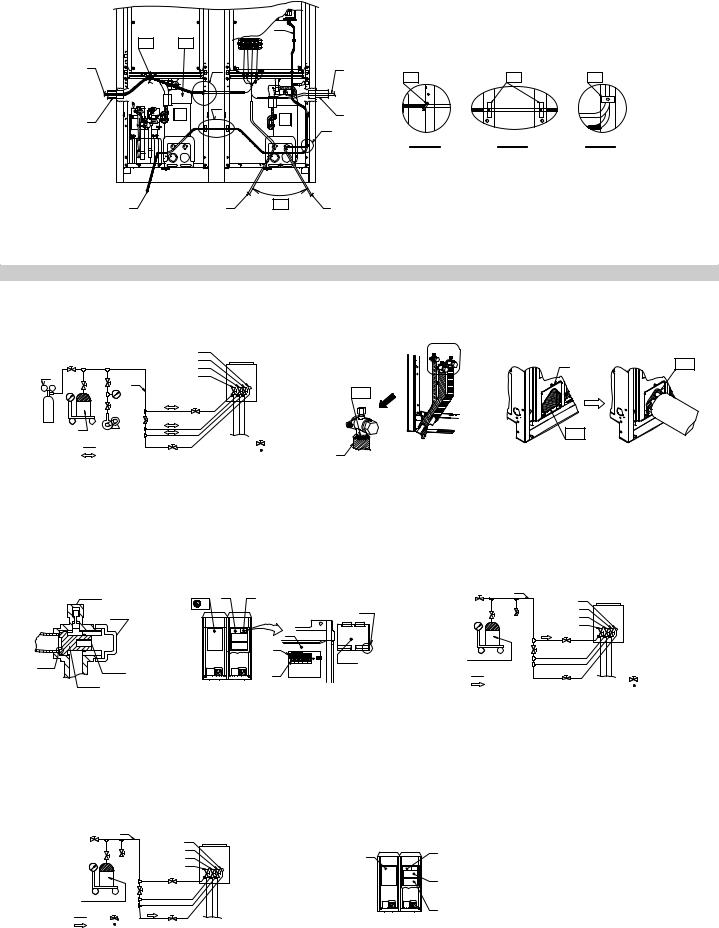
figure 21 |
|
figure 22 |
|
figure 23 |
|
|
|
11 |
|
|
1 |
12 |
|
|
|
|
3 |
|
9 |
|
|
|
A |
10 |
8 |
14 |
14 |
|
|
|
|
13 |
||
|
B |
|
2 |
|
|
2 |
|
|
|
|
|
|
|
C |
|
|
|
|
|
|
|
|
|
|
|
|
Part A |
Part B |
Part C |
4 |
5 |
6 |
7 |
figure 24
|
|
|
7 |
|
|
|
|
|
|
|
8 |
14 |
|
1 |
3 |
|
|
|
9 |
|
|
||
|
|
|
|
|
|
||
1 |
|
|
10 |
|
|
|
|
|
|
6 |
|
|
|
|
|
|
|
|
|
|
|
|
|
|
|
|
12 |
|
|
2 |
|
2 |
3 |
|
|
|
|
|
|
|
|
|
|
|
|
||
|
|
|
|
|
|
|
|
|
|
4 |
13 |
|
|
|
|
|
|
|
|
|
|
2 |
|
|
|
5 |
11 |
15 |
: 16 |
|
|
|
|
: 18 |
1 |
|
|||
|
|
|
( |
: 17 ) |
|
||
|
|
: 19 |
|
|
|
|
|
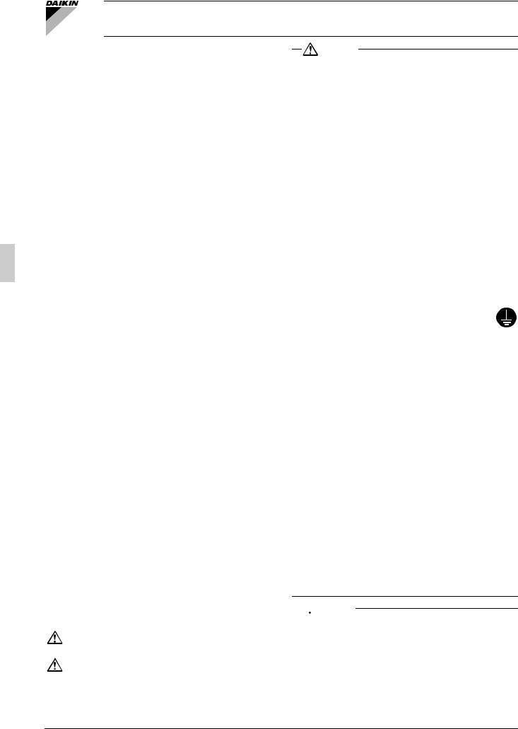
figure 25 |
|
figure 26 |
|
figure 27 |
1 |
3 |
1 |
2 |
|
3 |
11 |
|
4 |
|||||
|
4 |
|
|
|
||
|
|
8 |
|
5 |
|
|
|
2 |
|
|
|
||
|
|
|
|
6 |
|
|
|
|
|
5 |
|
7 |
|
|
|
|
1 |
9 |
|
|
|
|
|
|
|
||
|
|
|
|
|
|
|
|
6 |
|
10 |
|
|
|
|
2 |
2 |
|
|
|
5 |
3 |
|
|
|
||
7 |
|
8 |
|
|
||
|
: 13 |
|
|
|||
|
4 |
|
: 15 |
|||
|
|
12 |
|
|||
|
|
: 14 |
( |
: 16 ) |
||
|
|
|
|
figure 28 |
|
figure 29 |
|
figure 30 |
3
4 |
11 |
|
5 |
2 |
1 |
6 |
|
|
7 |
|
|
1 |
|
|
9 |
3 |
|
2 |
|
10 |
|
|
|
|
4 |
|
|
|
|
8 |
|
: 13 |
|
: 15 |
|
|
|
|
12 |
||
: 14 |
( |
: 16 ) |
|
figure 31 |
|
figure 32 |

3P201178-4B EM07A013 (0705) HT
REYQ8PY1B |
REYQ14PY1B |
|
Installation manual |
REYQ10PY1B |
REYQ16PY1B |
VRVIII System air conditioner |
|
REYQ12PY1B |
|
|
|
CONTENTS |
|
|
1. |
FIRST OF ALL ......................................................................... |
1 |
|
1-1. Safety considerations........................................................ |
1 |
|
1-2. Special notice of product................................................... |
2 |
|
1-3. Disposal requirements ...................................................... |
2 |
2. |
INTRODUCTION...................................................................... |
2 |
|
2-1. Combination ...................................................................... |
2 |
|
2-2. Standard supplied accessories ......................................... |
3 |
|
2-3. Option accessory .............................................................. |
3 |
|
2-4. Technical and Electrical specifications ............................. |
3 |
|
2-5. Main components.............................................................. |
3 |
3. |
SELECTION OF LOCATION ................................................... |
3 |
4. |
INSPECTING AND HANDLING THE UNIT ............................. |
4 |
5. |
PLACING THE UNIT................................................................ |
4 |
6. |
REFRIGERANT PIPING .......................................................... |
4 |
|
6-1. Selection of piping material and Refrigerant |
|
|
branching kit...................................................................... |
4 |
|
6-2. Protection against contamination when installing pipes.... |
4 |
|
6-3. Pipe connection ................................................................ |
5 |
|
6-4. Connecting the refrigerant piping...................................... |
5 |
|
6-5. Example of connection...................................................... |
6 |
7. |
FIELD WIRING ........................................................................ |
9 |
|
7-1. Power circuit, safety device and cable requirements ........ |
9 |
|
7-2. Wiring Connection Example for Whole System ................ |
9 |
|
7-3. Leading wire Procedure .................................................... |
9 |
|
7-4. Transmission Wiring Connection Procedure................... |
10 |
|
7-5. Power Wiring Connection Procedure .............................. |
10 |
|
7-6. Procedure for Wiring Inside Units ................................... |
10 |
8. |
AIR TIGHT TEST AND VACUUM DRYING ........................... |
11 |
9. |
PIPE INSULATION ................................................................ |
11 |
10. |
CHECKING OF DEVICE AND |
|
|
INSTALLATION CONDITIONS .............................................. |
12 |
11. |
ADDITIONAL REFRIGERANT CHARGE AND |
|
|
CHECK OPERATION ............................................................ |
12 |
|
11-1. Before working .............................................................. |
12 |
|
11-2. Procedure of Adding Refrigerant charging and check |
|
|
operation ....................................................................... |
13 |
12. |
ONSITE SETTINGS............................................................... |
16 |
13. |
TEST RUN ............................................................................. |
16 |
|
13-1. Before test run............................................................... |
16 |
|
13-2. Test Run........................................................................ |
16 |
|
13-3. Checks After Test Run .................................................. |
16 |
14. |
CAUTION FOR REFRIGERANT LEAKS ............................... |
16 |
1.FIRST OF ALL
•This document is an installation manual for the Daikin REYQ-P Series VRV Inverter. Before installing the unit, read this manual thoroughly, and following the instructions contained in it.
After installation, do a test run to make sure the unit runs properly, and then explain how to operate and take care of the unit to the customer, using the operation manual.
Lastly, make sure the customer keeps this manual, along with the operation manual, in a safe place.
1-1 Safety considerations
Please read these “Safety considerations” carefully before installing air conditioning unit and be sure to install it correctly. The safety precautions listed here are divided into two categories.
In either case, important safety information is listed which must be read carefully.
Warning........Failure to observe a warning may result in death or serious injury.
Caution.........Failure to observe a caution may result in injury or damage to the unit.
These too might lead to serious injury depending on the circumstances.
Warning
•Ask your dealer or qualified personnel to carry out installation work. Do not try to install the machine yourself.
Improper installation may result in water leakage, electric shocks or fire.
•Perform installation work in accordance with this installation manual. Improper installation may result in water leakage, electric shocks or fire.
•When installing the unit in a small room, take measures against to keep refrigerant concentration from exceeding allowable safety limits in the event of refrigerant leakage.
Excessive refrigerant in a closed ambient can lead to oxygen deficiency. Contact your dealer for more information.
•Be sure to use only the specified accessories and parts for installation work.
Failure to use the specified parts may result in water leakage, electric shocks, fire or the unit falling.
•Install the air conditioner on a foundation strong enough to withstand the weight of the unit.
A foundation of insufficient strength may result in the unit falling and causing injuries.
•Carry out the specified installation work after taking into account strong winds, typhoons or earthquakes.
Improper installation work may result in the unit falling and causing accidents.
•Make sure that a separate power supply circuit is provided for this unit and that all electrical work is carried out by qualified personnel according to local and national regulations and this installation manual.
An insufficient power supply capacity or improper electrical construction may lead to electric shocks or fire.
•Be sure to establish an earth.
Do not earth the unit to a utility pipe, arrester or telephone earth.
Incomplete earth may cause electrical shock or fire.
A high surge current from lightning or other sources may cause damage to the air conditioner.
•Be sure to install an earth leakage breaker.
Failure to install an earth leakage breaker may result in electric shocks or fire.
•Before touching electrical parts, turn off the power. Failure to turn off the power may result in electric shocks.
•Make sure that all wiring is secured, the specified wires are used, and no external forces act on the terminal connections or wires. Improper connections or installation may result in the terminals overheating or fire.
•When wiring the power supply and connecting the remote controller wiring and transmission wiring, position the wires so that the EL.COMPO.BOX lid can be securely fastened.
Improper positioning of the EL.COMPO.BOX lid may result in electric shocks or fire.
•If the refrigerant gas leaks during installation, ventilate the area immediately.
Toxic gas may be produced if the refrigerant gas comes into contact with fire.
•After completing the installation work, check that the refrigerant gas does not leak.
Toxic gas may be produced if the refrigerant gas leaks into the room and comes into contact with a source of fire, such as a fan heater, stove or cooker.
•Do not directly touch the refrigerant leaked from refrigerant piping connections.
Frostbite may be caused.
•Do not allow children to mount on the outdoor unit, or avoid placing any object on it. Falling or tumble may result in injury.

 Caution
•While following the instructions in this installation manual, install drain piping in order to ensure proper drainage and insulate piping in order to prevent condensation.
Improper drain piping may result in water leakage and property damage.
•Install the indoor, BS and outdoor units, power supply wiring and connecting wiring at least 1 meter away from televisions or radios in order to prevent image interference or noise.
(Depending on the radio waves, a distance of 1 meter may not be sufficient enough to eliminate the noise.)
1 |
English |
•The indoor and BS unit should be installed as far away from fluorescent lighting as possible.
Remote controller (wireless kit) transmitting distance can result shorter than expected in rooms with electronic fluorescent lamps (inverter or rapid start types).
•Do not install the air conditioner in the following locations:
(a)where a mineral oil mist or an oil spray or vapor is produced, for example in a kitchen.
Plastic parts may deteriorate and fall off or result in water leakage.
(b)where corrosive gas, such as sulfurous acid gas, is produced. Corroding copper pipes or soldered parts may result in refrigerant leakage.
(c)near machinery emitting electromagnetic waves. Electromagnetic waves may disturb the operation of the control system and result in a malfunction of the unit.
(d)where flammable gas may leak, where there are carbon fiber or ignitable dust suspensions in the air, or where volatile flammables such as thinner or gasoline are handled.
Operating the unit in such conditions may result in fire.
(e)Locations where small animals might build nests inside the unit. If small animals enter and come in contact with electrical parts, this can cause malfunctions, smoke, and fire.
1-2 Special notice of product
[CLASSIFICATION]
This air conditioner comes under the term “appliances not accessible to the general public”.
[EMC CHARACTERISTICS]
VRVIII System is a class A product. In a domestic environment this product may cause radio interference in which case the user may be required to take adequate measures.
[REFRIGERANT]
VRVIII System use R410A refrigerant.
•The refrigerant R410A requires strict cautions for keeping the system clean, dry and tight.
Read the chapter “REFRIGERANT PIPING” carefully and follow these procedures correctly.
A.Clean and dry
Foreign materials (including mineral oils such as SUNISO oil or moisture) should be prevented from getting mixed into the system.
B.Tight
Take care to keep the system tight when installing.
R410A does not contain any chlorine, does not destroy the ozone layer, and does not reduce the earth’s protection against harmful ultraviolet radiation.
R410A can contribute slightly to the greenhouse effect if it is released.
•Since R410A is a mixed refrigerant, the required additional refrigerant must be charged in its liquid state. If the refrigerant is charged in a state of gas, its composition changes and the system will not work properly.
Limit by the total maximum refrigerant charge
The total maximum refrigerant charge of a VRVIII system must be below 100kg, this to be in accordance with CE requirement (EN60335-2-40 standard).
This means that in case the total maximum refrigerant charge of the system (factory and additional charge) is equal to or more than 100kg you must divide your multiple outdoor system into smaller independent systems, each containing less than 100kg refrigerant charge.
For factory charge, refer to the unit name plate.
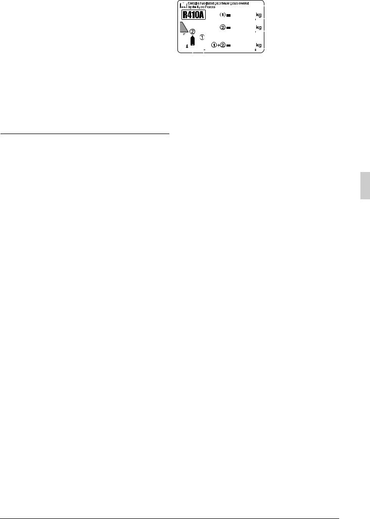
Important information regarding the refrigerant used
This product contains fluorinated greenhouse gases covered by the Kyoto Protocol. Do not vent gases into the atmosphere. Refrigerant type : R410A
GWP (1) value : 1975
(1) GWP = global warming potential Please fill in with indelible ink,
Q the factory refrigerant charge of the product,
Q the additional refrigerant amount charged in the field and
Q

|
|
|
|
|
|
|
|
|
|
|
4 |
1 |
factory refrigerant charge |
|||||
|
|
|
|
|
|
|
|
|
|
|
|
|
|
|
||||
|
|
|
|
|
|
|
|
|
|
|
|
|
|
|
|
|
||
|
|
|
|
|
|
|
|
|
|
|
|
|
|
|
|
|
|
of the product : see unit |
|
|
|
|
|
|
|
|
|
|
|
|
|
|
1 |
|
name plate (2) |
||
|
|
|
|
|
|
|
|
|
|
|
|
|
|
|
||||
|
|
|
|
|
|
|
|
|
|
|
|
|
||||||
|
|
|
|
|
|
|
|
|
|
|
|
|
|
|
|
2 |
2 |
additional refrigerant |
|
|
|
|
|
|
|
|
|
|
|
|
|
|
|
amount charged in the field |
|||
|
|
|
|
|
|
|
|
|
|
|
|
|
|
|
||||
|
|
|
|
|
|
|
|
|
|
|
|
|
|
|
|
3 |
3 |
total refrigerant charge |
|
|
|
|
|
|
|
|
|
|
|
|
|
|
|
|
4 |
Contains fluorinated |
|
|
|
|
|
|
|
|
|
|
|
|
|
|
|
|
|
|
|
greenhouse gases covered |
|
6 |
5 |
|
|
|
|
|
|
|
|
|
|
|
by the Kyoto Protocol |
||||
|
|
|
|
|
|
|
|
|
|
|
|
|
|
|
|
|
5 |
outdoor unit |
|
|
|
|
|
|
|
|
|
|
|
|
|
|
|
|
|
6 |
refrigerant cylinder and |
|
|
|
|
|
|
|
|
|
|
|
|
|
|
|
|
|
|
manifold for charging |
(2) In case of multiple outdoor systems, only 1 label must be adhered, mentioning the total factory refrigerant charge of all outdoor units connected on the refrigerant system.
[DESIGN PRESSURE]
Since design pressure is 4.0MPa or 40bar (for R407C units : 3.3MPa or 33bar), the wall thickness of pipes should be more carefully selected in accordance with the relevant local and national regulations.
1-3 Disposal requirements
Dismantling of the unit, treatment of the refrigerant, oil and eventual other parts, should be done in accordance with the relevant local and national regulations.
2.INTRODUCTION
•REYQ-P series are designed for outdoor installation and used for cooling and heating aplications. The REYQ8-16P system is exclusive unit for single outdoor unit system. The unit can not use for independent unit of multi outdoor unit system.
With this system, rated cooling capacity from 22.4kW to 45.0kW and rated heating capacity from 25.0kW to 50.0kW can be achieved.
•The BS units that combined with REYQ-P system for changing the refrigerant flow to indoor units are BSVQ100, 160, 250P type only. To combine with other type BS unit will cause malfunction.
•The indoor units that combined with REYQ-P system for air conditioning are Daikin VRV series indoor units that compatible with R410A. To learn which indoor units are compatible with R410A, refer to the product catalogs. To combine with other refrigerant indoor unit will cause malfunction.
2-1 Combination
• The indoor units can be installed in the following range.
Outdoor unit |
Total capacity of indoor units |
|
REYQ8PY1B ....................................... |
100 |
~ 260 |
REYQ10PY1B ..................................... |
125 |
~ 325 |
REYQ12PY1B ..................................... |
150 |
~ 390 |
REYQ14PY1B ..................................... |
175 |
~ 455 |
REYQ16PY1B ..................................... |
200 |
~ 520 |
•If the total capacity of the connected indoor units exceeds the capacity of the outdoor unit, cooling and heating performance may drop when running the indoor units. See the capacity table in the Engineering Data Book for details.
English |
2 |
 Loading...