


Daikin JEHCCU0050M1, JEHCCU0075L1, JEHCCU0088M1, JEHCCU0175L1, JEHCCU0150M1 Installation manuals
...Installation Manual
Medium temperature application |
Low temperature application |
JEHCCU0050M1 |
JEHCCU0075L1 |
JEHCCU0088M1 |
JEHCCU0175L1 |
JEHCCU0150M1 |
JEHCCU0175L3 |
JEHCCU0150M3 |
JEHCCU0225L1 |
JEHCCU0225M1 |
JEHCCU0225L3 |
JEHCCU0225M3 |
JEHCCU0350L3 |
JEHCCU0300M1 |
JEHCCU0400L3 |
JEHCCU0300M3 |
JEHCCU0725L3 |
JEHCCU0400M3 |
JEHCCU0825L3 |
JEHCCU0500M3 |
|
JEHCCU0600M3 |
|
JEHCCU0675M3 |
|
JEHCCU0825M3 |
|
JEHCCU1000M3 |
|

Contents
1. |
Nomenclature |
2 |
2. |
Safety and Health |
2 |
3. |
Installation & commissioning |
2 |
4. |
Service and Maintenance |
4 |
5. |
Checklist |
5 |
6. |
Trouble Shooting |
5 |
7. |
Specifications |
6 |
8. |
Outline Drawings |
7 |
9. |
Electrical Data |
9 |
10. |
Declaration of conformity |
12 |
1.Nomenclature
JEHCCU 0150 M 1
1: Single Phase
3: Three Phase
Application
M: Medium Temperature
L: Low Temperature
Nominal Capacity in Horse Power
0150: 1.5 HP
J & E Hall Commercial Condensing Unit for Daikin
2.Safety and Health
Important Note
Only a qualified refrigeration engineer who is familiar with refrigeration systems and components, including all controls should perform the installation and start-up of the system. To avoid potential injury, use care when working around coil surfaces or sharp edges of metal cabinets. All piping and electrical wiring should be installed in accordance with all applicable codes, ordinances and local by-laws.
∙The electrical covers and condenser fan guard must remain fitted at all times.
∙Use of the condensing unit outside of design conditions and application for which units were intended may be unsafe and be detrimental to the unit, regardless short or long term operation.
∙The condensing units are not designed to withstand loads or stresses from other equipment or personnel. Such extraneous loads or stress may cause failure/leak/injury.
∙In some circumstances, a suction accumulator (not supplied) component may be required, it offers protection against refrigerant flood back during operation. It helps protect against off-cycle migration by adding internal free volume to the low side of the system.
∙Test must be conducted to ensure the amount of offcycle migration to the compressor does not exceed the compressor’s charge limit.
∙Wherever possible the system should be installed to utilize a pump down configuration.
∙After installation, the system should be allowed to run for 3 – 4 hours. The oil level should be checked after 3
– 4 hours run time and topped up as necessary. The oil level should be visible at least ½ - ¾ up the compr essor oil sight glass. For the details of the oil requirements, please refer to page 4 in the installation & commissioning section and page 4 in the service and maintenance section.
3.Installation & Commissioning
Unit site location
∙In order to achieve maximum cooling capacity, the installation location for condensing unit should be carefully selected.
∙Install the condensing unit in such a way so that hot air distributed by the condensing unit cannot be drawn in again (as in the case of short circuit of hot discharge air). Allow sufficient space for maintenance around the unit.
General Information
∙Ensure the unit received is the correct model for the intended application.
∙Ensure refrigerant, voltage, are suitable for the proposed application and environment.
∙Installation and maintenance are to be performed only by qualified personnel who are familiar with local codes and regulations, and experienced with this type of equipment.
∙The condensing unit is delivered with a nitrogen holding charge.
∙The condensing unit contains moving machinery and electrical power hazards. May cause severe injury or death. Disconnect and shut off power before installation or service of the equipment.
∙Refrigerant release into the atmosphere is illegal. Proper evacuation, handling and leak testing procedures must be observed at all times.
∙Units must be earthed and no maintenance work should be attempted prior to disconnecting the electrical supply.
∙Ensure that there is no obstruction of air flow into or out of the unit. Remove obstacles which block air intake or discharge.
∙The location must be well ventilated, so the unit can draw in and distribute plenty of air thus lowering the condensing temperature.
Rev 008/April 2009 |
2 |
All specifications are subjected to change by the manufacturer without prior notice |
|

∙To optimize the unit running conditions, the condenser coil must be cleaned at regular intervals.
Installation Clearance
∙The installation location should allow sufficient space for air flow and maintenance around the unit.
Field Piping
Important Note
Line sizing should only be determined by qualified personnel. All local codes of practice must be observed in the installation of refrigerant piping
To ensure satisfactory operation and performance, the following points should be noted for field piping arrangements,
∙Pipework routes must be as simple and as short as possible.
∙Avoid low points on pipework where oil can accumulate.
∙Suction gas velocity must be sufficient to ensure good oil return.
∙Use only clean, dehydrated refrigeration grade copper tube with large radius elbows.
∙Braze without over filling to ensure there is no excess solder into the tube.
∙To prevent oxidation, blow nitrogen through pipework when brazing.
∙Install insulation on all suction lines.
∙Adequately support all pipe work at a maximum of 2 meter intervals.
∙In vertical pipework, the use of U-trap and double suction risers is often required. These suction risers must always be fitted with a U-trap at the bottom and a P-trap at the top and never be higher than 4 meter unless a second U-trap system is fitted.
∙Recommend piping length less than 25m
Correct line sizing will minimize the pressure drop and maintain sufficient gas velocity for proper oil return.
Compressor handling
To ensure compressor reliability, the condensing unit and the compressor must not be tilt greater than an angle of 45°. Otherwise, the compressor can fall from its 3 compressor housing prings, which results in noisy vibrations during operation.
Leak detection
∙Make sure that all manual valves are open
∙Perform a leak test of the system using nitrogen mixed with the refrigerant to be used
∙Do not use CFC for leak testing the condensing unit which will be used with HFC refrigerants
∙The use of leak testing fluids is not recommended as this may interact with the lubricants own additives
Pressure testing
∙When running a pressure test, always use an inert, dry gas such as Nitrogen
∙The pressure differential between the high and low side should not exceed 24 bar (350 psig)
∙Maximum test pressures are :
25 bar (370 psig) on the Low Side
30 bar (480 psig) on the High Side
Safety pressure switch settings
The Danfoss KP17 HP/LP pressure switch fitted to condensing units with auto reset for low pressure and manual reset for high pressure is NOT factory preset. Be sure that the high pressure setting does not exceed the receiver’s maximum service pressure.
High pressure safety
The high pressure safety switch is required to stop the compressor should the discharge pressure exceed the values shown in the following table. The high pressure switch can be set to lower values depending on the application and the ambient conditions
Refrigerant |
R404A |
R134a |
Cut Out (bar g) |
28 |
22.6 |
Cut Out (psig) |
405 |
325 |
Low pressure safety
The low pressure safety switch protects the compressor against deep vacuum operation, a potential cause of failure due to internal arching.
The low pressure safety cut should never be set below 0.1 bar (2 psig) as shown in the following table. For systems without pumpdown the LP switch signal contact shall be used to energize a low pressure safety alarm
Refrigerant |
R404A |
R134a |
Cut Out (bar g) |
0.1 |
0.4 |
Cut In (bar g) |
1.2 |
1.2 |
Rev 008/April 2009 |
3 |
All specifications are subjected to change by the manufacturer without prior notice |
|
Important Note
There must be no more than 12 compressor starts per hour. A higher number reduces the service life of the compressor. If necessary, use an anti-short-cycle timer in the control circuit. A three minutes time out is required.
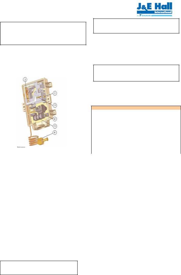
Fan speed controller*
The fan speed controller controls the speed of the condenser.
It keeps the condensing pressure at a steady level by changing the speed of the fan according to the required condensing pressure.
1)Adjusting screw
2)Bellows
3)Range setting pointer (dual marking 11 and 19 bar)
4)Change over switch
5)Terminal board
6)¼” flare with depression pin (7/16-20 UF)
Setting point can be increased by turning the adjusting screw clockwise. Setting point can be decreased by turning the adjusting screw counter clockwise. Adjustment should be within the range indicated for the setting pointer.
With the Change over switch you can choose between two settings:
Cut off: Fan motor stops when the pressure decreases below the value Pmin.
Min. speed: Fan motor operates at the Minimum Speed when the pressure decreases below the value Pmin.
F.V.S. = Full Voltage Set Point (pressure setting for maximum speed)
E.P.B. = Effective Proportional Band Pmin = (F.V.S. – E.P.B.)
* Except JEHCCU0050M1 / JEHCCU0088M1 /
JEHCCU0075L1
Vacuum - moisture removal
Important Note
Warning! – Disconnect the mains electrical supply before servicing or opening the unit
Important Note
Moisture prevents proper functioning of the compressor and the refrigeration system
Air and moisture reduce service life and increase condensing pressure causing abnormally high discharge temperatures likely to destroy the oil’s lubricating properties. The risk of acid formation is also increased by air and moisture and copper plating can be generated in this way. All these phenomena can be cause mechanical and electrical failure.
Important Note
Ensure that a good quality vacuum pump is used to pull a minimum vacuum of 250 microns (0.33 mbar)
Oil requirements
The polyoilester with the following characteristics must be used:
Characteristics of the oil
Property |
Specification |
Test method |
|
Viscosity at 40°C |
31 – 33 cSt |
ASTM D 445 |
|
Viscosity at 100°C |
5,6 cSt |
ASTM D 445 |
|
Density at 15,6 °C |
0,97 g/ml |
ASTM D |
|
4052 |
|||
|
|
||
Colour |
100 |
ASTM D |
|
1209 |
|||
|
|
||
Pour point |
-45°C (max) |
ASTM D 97 |
|
Flash point |
217°C |
ASTM D 93 |
|
Dielectric strength |
47 kV (min) |
ASTM D |
|
at 25°C |
1816 |
||
|
|||
Acid value (Tan) |
0,15 mg KOH/g (max) |
ASTM D 974 |
The initial oil charge is 600 cm³
Example: polyoilester (POE) oil type 160PZ from Danfoss.
Commissioning of the Condensing Unit
Please make sure that all manual service valves are fully open when starting the system for the first time.
This includes external shut off valves as well as liquid receiver valve in the unit.
4.Checklist
∙Ensure crankcase heater is energized minimum 12 hours prior to start up and permanently energized.
∙Check all electrical connections.
∙Check all electrical termination and circuits are correct.
∙Check compressor oil level.
∙Ensure the high low pressure controls are configured properly.
∙Ensure fan motor and fan blades are installed properly.
∙Observed the system pressures during the charging and initial operation process.
∙Continue to charge the system until sight glass is clear. Make sure that high pressure is > 12bar when doing this charge adjustment operation.
∙Check the compressor’s discharge and suction pressure, ensure it’s within operating range.
∙Check condenser fan, ensure warm air blowing off the condenser coil.
Rev 008/April 2009 |
4 |
All specifications are subjected to change by the manufacturer without prior notice |
|

∙Check evaporator blower, ensure it’s discharging cool air.
∙Check evaporator superheat and adjust expansion valve if necessary
5.Service and Maintenance
The condensing units are designed to give long life operation with minimum maintenance. However, they should be routinely checked and the following service schedule is recommended under normal circumstances:
The removal of the top, side and front panels ensures that all parts are accessible.
1.Compressor – Inspect at regular intervals
∙Check for refrigerant leaks on all joints and fittings.
∙Ensure that no abnormal noise or vibration is detected during test run.
∙Check the compressor oil levels and top up if required. The oil level should be ½ to ¾ way up the sight glass.
2.Condenser Fan Motor & Blade – Clean and inspect at regular intervals
∙Check for abnormal noise, vibration and fan imbalance.
∙Ensure that the fan motor is clean and spins freely.
∙Check that the condenser fan blade is clean and free from restriction.
∙Note: The Fan Motor is pre-lubricated and factory sealed so no maintenance is necessary.
3.Condenser Coil – Clean and inspect at regular intervals
∙Check and remove the dirt and debris between the fins using a suitable chemical coil cleaner.
∙Check and remove any obstacles which may hinder the airflow through the condenser coil.
4.Power Supply – Inspect at regular intervals
∙Check the running current and voltage for the condensing unit.
∙Check the electrical wiring and tighten the wires onto the terminal blocks if necessary.
Under normal circumstances:
∙Clean condenser coil every three months
∙Carry out leak test every month
∙Examine electrical cables and enclosures each year
∙Check and verify operation of all safety devices every three months, ensure crankcase heater is operational
∙Check sight glass and operating conditions
∙Check security of compressor mountings and the bolts that hold down the unit each year
6.Trouble Shooting
This troubleshooting guide describes some common condensing units failure. Consult qualified personnel before any corrective actions are taken.
Failure |
|
Possible Causes |
|
|
|
Fan does not work |
∙ |
Improper wiring |
∙ |
Fan motor faulty |
|
|
∙ |
Improper wiring |
|
∙ |
Defective contactor or coil |
Compressor does |
∙ |
System stopped because of |
not start |
∙ |
tripped of safety device. |
|
Defective start/run capacitor |
|
|
∙ |
Compressor faulty |
|
∙ |
Low refrigerant charge |
Insufficient cooling |
∙ |
Condenser coil dirty |
∙ |
Obstacle blocking air inlet/outlet |
|
|
∙ |
Improper thermostat setting |
Rev 008/April 2009 |
5 |
All specifications are subjected to change by the manufacturer without prior notice |
|
 Loading...