


INSTALLATION MANUAL
Installation Manual |
English |
|
ON / OFF VALVE KITS |
Türkçe |
|
Montaj Kılavuzu |
||
ON / OFF VALF KİTLERİ |
|
|
Installationshandbuch |
Deutsch |
|
ON / OFF VENTIL-SETS |
|
|
Guide de montage |
Français |
|
ON/OFF KIT DE VANNE |
|
|
Installatie Handboek |
Nederlandse |
|
ON/OFF VALVE KITSS |
|
|
Manual de Instalación |
Español |
|
KIT DE VÁLVULAS DE ENCENDIDO / APAGADO |
|
|
Manuale d’installazione |
Italiano |
|
KIT VALVOLA ON / OFF |
|
|
Εγχειρίδο εγκατάστασης |
ελληνικά |
|
ΣΕΤΣ ΒΑΛΒΙΔΩΝ ON/OFF |
||
|
||
Manual de Instalação |
Português |
|
KITS DE VÁLVULAS ON-OFF |
||
|
||
Руководство по установке |
Pусский |
|
КОМПЛЕКТЫ ДВУХПОЗИЦИОННЫХ КЛАПАНОВ |
||
|
||
Telepítési Kézikönyv |
Magyar |
|
ON / OFF SZELEP KÉSZLETEK |
||
|
Models :
EK2MV2B10C5
EK2MV3B10C5
EK4MV2B10C5
EK4MV3B10C5
3PW90202-1

Dear Customer,
We thank you for choosing DAIKIN products.
This installation guide contains explanations about the safety and standard operating.
Before installation and maintenance of Fan coil units , please read safety and warnings and keep guide carefully for installation and maintenance process.
Please give importance to the general warnings.
This appliance is intended to be used by expert or trained users in shops, in light industry and on farms, or for commercial use by lay persons.
This untreated household waste electrical and
!electronic products should not be confused. Do not disassemble the system on your own, Removal system, coolant, oil and other parts should be performed by a qualified plumber in accordance with the relevant legislation. The units should be operated in special facilities for reuse and recycling. Please help in preventing potential negative consequences for human and the environment health by providing the product is disposed of correctly. For more information please contact the autorized person or a person who performed the installation
Manufacturer Firm:
DAIKIN EUROPE N.V.
Zandvoordestraat 300, B-8400 Oostende, Belgium
Tel: (+32)59/55 81 11
Fax: (+32)59/55 88 99
Production Plant :
Daikin Isıtma ve Soğutma Sistemleri San. Tic. A.Ş. 2. OSB 54300 Hendek/SAKARYA,TURKEY
Tel |
: +90264 |
616 27 00 |
Fax |
: +90264 |
654 58 45-46 |
Made in Turkey

ON/OFF VALVE KITS
Model Name |
Description |
|
|
EK2MV2B10C5 |
2 Pipes 2 Way Valve Kit |
|
|
EK2MV3B10C5 |
2 Pipes 3 Way Valve Kit |
|
|
EK4MV2B10C5 |
4 Pipes 2 Way Valve Kit |
|
|
EK4MV3B10C5 |
4 Pipes 3 Way Valve Kit |
|
|
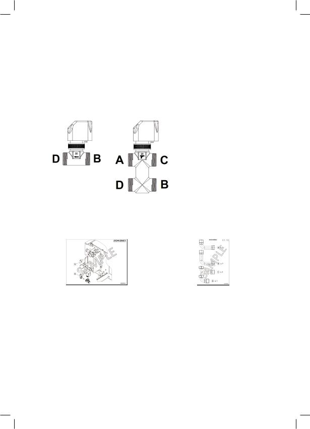
Figure 1
Figure2
The 2-way or 3-way ON/OFF valve kits, connected to the DAIKIN controllers, helps to set the room temperature by interrupting the water flow to the heat exchanger. The kits are available with various fittings for all FWE units, both for 2-pipe and for 4-pipe systems.
The position of water input, connections to heat exchanger and water returning to the circuit is shown in figure 1 (2 ways type) and figure 2 (3 ways type) according to the indications on the valve body.
A= Heat exchanger water outlet
B= Water inlet from circuit
C= Water returning to circuit
D= Heat exchanger water inlet
The connection must be made by using “Piping Connection Diagrams” and “Pipe Description Schemas” inside the kit box for each models. All fittings are specified in “Pipe Description Schema” with 1:1 scale to facilitate finding the correct fitting part.
Figure for; |
Figure for; |
4 Pipe / 2 Way Valve Model Piping Connection Diagram |
4 Pipe / 2 Way Valve Model Pipe Description Schema |
|
|
Piping Connection Diagram |
Pipe Description Schema |
In these files, the letters indicate the corresponding |
In these files, part drawings are scaled 1:1 and the |
fittings in “pipe description schema”. The numbers |
numbers at the right of the part drawings indicate |
indicated the assembly sequence that has to be |
quantity. |
followed. |
|
|
|
! WARNING:
•Forelectricalconnectiontothecontroller,refertothewiringdiagramofthecontroller.
•Eachunitrequiresaswitch(IL)onthefeederlinewithadistanceofatleast3mmbetweentheopeningcontacts,andasuitable safetyfuse(F).
y |
1 |
|
|

The KIT Consist Of;
•2 ways valve body with 2 connections and 3-ways valve body with 4 connections with built-in by-pass made of brass, maximum working pressure 16 bar.
•Electro-thermal actuator having the following specifications:
•Power supply; 230VAC, activation; NC (Normal Close) and ON/OFF,
•Total opening time: 3 minutes.
•Cable lenght: 1 meter
•Protection class: IP44 to EN 60529
•Power consumption (normal operation): 2,5W
!Caution: During mounting hydraulic kit to unit should be used the required amount of extra sealing material to seal between fitting connection points for unmounted units.
!Caution: After mounting hydraulic kit, installer must be ensured that there is no any leakage on all connection points.
Hydraulic kit for the installation of the valve on the heat exchanger.
The flow resistance of the valve is obtained from the following formula:
Pw = (Qw/Kv)2
Valve |
Kv Direct Passage |
Kv By-Pass |
|
|
|
2 Ways 3/4" |
2,8 |
- |
|
|
|
3 Ways 3/4" |
2,8 |
1,8 |
|
|
|
Where:
Pwistheflowresistanceexpressedinkg/cm2.
Qwisthewaterflowrateexpressedinm3/h.
Kvistheflowrateidentifiedinthetable.
2
Değerli Müşterimiz,
DAIKIN ürünlerini seçtiğiniz için teşekkür ederiz.
Bu kurulum kılavuzu, güvenlik, standart işletim ile ilgili açıklamaları içermektedir.
Satın aldığınız Fan Coil’in kurulumu ve işleme almadan önce bakım ve kurulum işlemi için güvenlik ve uyarıları dikkatlice okuyunuz ve kılavuzunuzu saklayınız.
Genel uyarılara önem veriniz.
Bu cihaz, mağazalar, hafif endüstri ve çiftliklerdeki uzmanlar veya eğitimli kullanıcılar tarafından veya meslekten olmayan kişilerce ticari amaçla kullanılmak üzere tasarlanmıştır.
Bu ürün “Atık Elektrikli ve Elektronik Eşyaların Kontrolü
!Yönetmeliği”ne tabidir. Atık ürünler belirlenen aktarma ve geri dönüştürme merkezlerine götürülmelidir.Ayrıntılar için ürünü satınaldığınız firmaya veya bağlı olduğunuz belediyenin ilgili birimine başvurunuz.
Bu sadece Avrupa Birliği ülkeleri için geçerlidir.
AEEE Yönetmeliğine uygundur.
İmalatçı Firma :
Daikin Isıtma ve Soğutma Sistemleri San. Tic. A.Ş.
Hürriyet Mah. Yakacık D-100 Kuzey Yan Yol No :49/1-2 Kartal/ İSTANBUL/TÜRKİYE
Tel |
: 0216 453 27 00 |
Fax |
: 0216 671 06 00 |
Üretim Yeri :
Daikin Isıtma ve Soğutma Sistemleri San. Tic. A.Ş. 2. OSB 54300 Hendek/SAKARYA
Tel |
: 0264 616 27 00 |
Fax |
: 0264 654 58 45-46 |
Kullanım Ömrü :
Gümrük ve Ticaret Bakanlığı Tüketicinin Korunması ve Piyasa Gözetimi Genel Müdürlüğü tarafından tespit edilen kullanım ömrü 10 yıldır.
444 999 0 • www.daikin.com.tr
Türkiye’de üretilmiştir.
ON/OFF VANA KİTLERİ
Model Adı |
Tanımlama |
|
|
EK2MV2B10C5 |
2 Borulu 2 Yollu Vana Kiti |
|
|
EK2MV3B10C5 |
2 Borulu 3 Yollu Vana Kiti |
|
|
EK4MV2B10C5 |
4 Borulu 2 Yollu Vana Kiti |
|
|
EK4MV3B10C5 |
4 Borulu 3 Yollu Vana Kiti |
|
|
Şekil1
Şekil2
DAIKIN oda termostatları ile 2 ya da 3 yollu ON / OFF vana kullanımı, set edilen oda sıcaklığında ısı eşanjöründen geçen su akışın kontrolünü sağlamaktadır. Vana kitleri çeşitli bağlantı elemanları ile tüm 2 borulu ve 4 borulu FWE model cihazlarda kullanılabilir.
Vana gövdesi üzerindeki işaretlemenin pozisyonu, su girişi, ısı eşanjörü bağlantıları ve devreye su dönüşü şekil 1 (2 yollu vana) ve şekil 2’de (3 yollu vana) gösterilmiştir.
A= Isı eşanjöründen su çıkış tarafı
B= Akış devresinden su giriş tarafı
C= Akış devresine su dönüşü tarafı
D= Isı eşanjörüne su giriş tarafı
Tüm modeller için bağlantılar, kit kutusu içerisinden çıkan “Boru Bağlantı Diyagramları” ve “Boru Tanıtım Şemaları” kullanılarak belirtilen şekilde yapılmalıdır. Bağlantı elemanlarını, kolayca ayırt edilebilmeleri için “Boru Tanıtım Şemaları”nda 1:1 ölçekle gösterilmiştir.
ÖrnekResim; |
ÖrnekResim; |
4 Borulu 2 Yollu Vanalı Model Boru Bağlantı Diyagramı |
4 Borulu 2 Yollu Vanalı Model Boru Tanıtım Şeması |
|
|
Boru Bağlantı Diyagramı |
Boru Tanıtım Şeması |
Bu dokümanlarda, harfler, “boru tanıtım |
Bu dokümanlarda, harfler, kullanılacak bağlantı |
şemaları”nda gösterilen bağlantı elemanlarını |
elemanlarını belirtmektedir. (1:1 ölçeğinde) |
belirtir. Sayılar, bağlantıların doğru bir şekilde |
Sayılar, kullanılacak bağlantı elemanı miktarlarını |
yapılması için montaj sırasını göstermektedir. |
göstermektedir. |
Montaj işlemi belirtilen işlem sırasıyla yapılmalıdır. |
|
|
|
! UYARI:
•Vanakablolarınınodakontrolünitesineelektrikbağlantısı,odakontrolünitesininelektrikdevreşemasınagöreyapılır.
•Herüniteiçin,beslemehattıüzerindeayırmatertibatıileuygungüvenliksigortasıarasındaenaz3mmmesafeolacakşekildebir anahtarbulundurmalıdır.
1
KİT İçeriği;
•Pirinç malzemeden 16 bar maksimum çalışma basıncına sahip 2 yollu vanalar 2 portlu, 3 yollu vanalar 4 portlu (by-pass özellikli) kullanılmaktadır.
•Elektro-termal aktuatör özellikleri:
•Güç beslemesi; 230VAC, çalışma; NC (Normalde Kapalı) ve ON/OFF,
•Toplam açılma süresi; 3 dakika
•Kablo uzunluğu; 1 metre
•Koruma sınıfı; IP44 (EN 60529)
•Güç tüketimi (normal çalışma); 2,5W
!Dikkat: Fabrika montajlı olmayan cihazlar için hidrolik kitin montajı esnasında bağlantı noktalarında sızıntı önleme amaçlı gerekli miktarda ilave sızdırmazlık malzemesi kullanılmalıdır.
!Dikkat: Su bağlantılarının montajı sonrası tüm bağlantılarda herhangi bir sızdırma olmadığından emin olunmalıdır.
Hidrolik kit, valflerin ısı eşanjörüne montajı amaçlı kullanılmalıdır.
Valf akış direnci aşağıda belirtilen formül ile hesaplanır.
Pw = (Qw/Kv)²
Vana |
Kv Direkt Geçiş |
Kv By-Pass |
|
|
|
2 Yollu 3/4" |
2,8 |
- |
|
|
|
3 Yollu 3/4" |
2,8 |
1,8 |
|
|
|
Birimler:
Pw;akışdirencinin“kg/cm2”olarakifadesidir.
Qw;suakışdebisinin“m3/h”olarakifadesidir
Kv;Tablodavanaakışdebisininifadesidir.
2
Sehr geehrte Kundin, Sehr geehrter Kunde,
Wir bedanken uns dafür, dass Sie sich für DAIKINProdukte entschieden haben.
Dieses Montagehandbuch beinhaltet Erläuterungen über die Sicherheit und den Standardbetrieb.
Bitte lesen Sie die Sicherheitsbestimmungen und Hinweise, bevor Sie die Montage und Wartung der Gebläsekonvektoren vornehmen und und halten Sie sich bei der Montage und den Wartungsabwicklungen an die Vorgaben dieses Handbuches.
Bitte beachten Sie die allgemeinen Hinweise.
Dieses Gerät ist dazu bestimmt, von Experten oder geschulten Anwendern in Geschäften, in der Leichtindustrie und auf Bauernhöfen oder für den gewerblichen Gebrauch durch Laien verwendet zu werden
Dieser unbehandelte Hausmüll, elektrische und elektronische Produkte dürfen
!System, Kühlmittel, Öl und andere Teile sollten von einem qualifizierten Installateur in Übereinstimmung mit den einschlägigen Rechtsvorschriften durchgeführt werden. Die Geräte sollten in speziellen Einrichtungen für die Wiederverwendung und das Recycling betrieben werden. Bitte helfen Sie bei der Verhütung möglicher negativer Folgen für Mensch und Umweltgesundheit, indem sie das Produkt ordnungsgemäß entsorgen. Für weitere Informationen kontaktieren Sie bitte eine zuständige Person oder den Monteur durchgeführtnicht vermischt werden. Zerlegen Sie das System nicht selbst. Removal
Herstellerfirma:
DAIKIN EUROPE N.V.
Zandvoordestraat 300, B-8400 Oostende, Belgien
Tel : (+32)59/55 81 11
Fax: (+32)59/55 88 99
Produktionsstätte:
Daikin Isıtma ve Soğutma Sistemleri San. Tic. A.Ş. 2. OSB 54300 Hendek/Sakarya, Türkei
Tel |
: +90264 |
616 27 00 |
Fax |
: +90264 |
654 58 45-46 |
Hergestellt in der Türkei

ON/OFF VENTIL-SETS
Modellname |
Beschreibung |
|
|
EK2MV2B10C5 |
2-Röhren-2-WegeVentil-Set |
|
|
EK2MV3B10C5 |
2-Röhren3-WegeVentil-Set |
|
|
EK4MV2B10C5 |
4-Röhren2-WegeVentil-Set |
|
|
EK4MV3B10C5 |
4-Röhren3-WegeVentil-Set |
|
|
Abbildung1
Abbildung2
Das2-Wege-oder3-Wege-Ventil-Set,angeschlossenandasDAIKIN Steuergerät, hilft bei der Regelung der Raumtemperatur durch die Unterbrechung des Wasserzuflusses zum Wärmetauscher. Die Sets sind erhaltbar mit verschiedenen Ausstattungen für alle FWEBaueinheiten, sowohl für 2-Röhren- als auch 4-Röhren-Systeme.
Der Stand der Wassereingabe, Verbindungen zum Wärmetauscher und des zum Kreislauf zurückfliessenden Wassers sind in Abbildung 1 (2-Wegetyp) und in Abbildung 2 (3-Wegetyp) entsprechend den Indikationen auf dem Ventilgehäuse dargestellt.
A= Wärmetauscher-Wasserabflussrohr
B= Wassereinfluss vom Kreislauf
C= Wasserrückfluss zum Kreislauf
D= Wassertauscher-Wasserzuflussrohr
Die Verbindungen sind anhand der “Rohrleitungsdiagramme” und der “Rohrbeschreibungsschemas” im Setkasten für jedes Modell durchzuführen. Alle Ausstattungen sind im “Rohrbeschreibungsschema” im Verhältnis 1:1 aufgezeigt, um die Auffindung des richtigen Ausstattungsteils zu erleichtern.
Abbildungfür: |
Abbildungfür: |
4-Röhren-/2-Wege-VentilmodellRohrleitungsdiagramm |
4-Röhren-/2-Wege-VentilmodellRohrbeschreibungsschema |
|
|
Rohrleitungsdiagramm |
Pipe Beschreibung Schema |
In diesen Akten weisen die Buchstaben |
In diesen Akten stehen die Zeichnungen der Teile |
auf die entsprechenden Ausstattungen im |
im Verhältnis 1:1 und die Nummern rechts der |
“Rohrbeschreibungsschema” hin. Die Nummern |
Teilezeichnungen weisen auf die Menge hin. |
weisen auf die Montagereihenfolge hin, die zu |
|
verfolgen ist. |
|
|
|
! WARNUNG:
•FürdieStromverbindungzumSteuergerätwirdaufdasSchaltungsdiagrammdesSteuergerätesverwiesen.
•JedeBaueinheitbedarfeinesSchalters(IL)aufderAnschlussliniemiteinemAbstandvonmindestens3mmzwischendenÖffnungskontakten,undeinerangemessenenGeräteschutzsicherung(F).
1
Das SET besteht aus;
•2-Wege-Ventilgehäuse mit 2Verbindungen und 3-Wege-Ventilgehäuse mit 4Verbindungen mit eingebauter Umgehung bestehend aus Messing, maximaler Betriebsdruck 16 Bar.
•Elektro-thermal Auslöser mit folgenden Spezifikationen:
•Stromversorgung; 230VAC, Aktivation; NC (Normaler Schluss) und ON/OFF,
•Gesamtöffnungszeit: 3 Minuten.
•Kabellänge: 1 Meter
•Schutzklasse: IP44 zu EN 60529
•Stromverbrauch (normaler Betrieb): 2,5W
!Achtung: Während der Montage der hydraulischen Ausstattung an die Baueinheit sollte die erforderliche Menge an extra Abdichtungsmaterial verwendet werden, um zwischen den Ausstattungsverbindungsstellen für nicht angebrachte Baueinheiten zu dichten
!Achtung: Nach der Montage des hydraulischen Ausstattung muss der Installateur sicherstellen, dass nichts aus den Verbindungsstellen ausläuft.
Hydraulische Ausstattung für die Installation des Ventils am Wärmetauscher.
Der Strömungswiderstand des Ventils wird anhand der folgenden Formel errechnet: Pw = (Qw/Kv)²
Ventil |
Kv Direktdurchfluss |
Kv Umgehung |
|
|
|
2 Ways 3/4" |
2,8 |
- |
|
|
|
3 Ways 3/4" |
2,8 |
1,8 |
|
|
|
Wobei:
PwstehtfürdenStrömungswiderstandausgedrcktinkg/cm2.
Qw stehtfürdasWasserdurchflussleistungausgedrücktin m3/h.
Kv stehtfürdas inderTabelleaufgeführteDurchflussleistung.
2
Cher client,
Nous vous remercions d’avoir choisi les produits DAIKIN.
Ce guide d’installation contient des explications concernant la sécurité et l’exploitation standard.
Avant l’installation et la maintenance des unités de ventiloconvecteurs, s’il vous plaît lire la sécurité et les avertissements et conservez ce manuel d’utilisation attentivement pour l’installation et le processus de maintenance.
S’il vous plaît donner de l’importance aux avertissements généraux.
Cet appareil est destiné à être utilisé par des utilisateurs expérimentés ou par des experts ayant pris la formation dans les magasins, dans l’industrie d’éclairage et dans les fermes ou bien par des personnes travaillant hors du secteur pour les fins commerciales.
Les produits non traités des déchets ménagers ne doivent pas être confondus
!par vousmême. Le système, le réfrigérant, l’huile, et les autres doivent être démontés par un plombier qualifié, conformément à la législation pertinente. La réutilisation et le recyclage des ces unités doivent être effectués dans les installations spéciales. S’il vous plaît aider à prévenir les conséquences négatives potentielles pour la santé humaine et l’environnement en fournissant la destructioncorrecteduproduit.Pourplusd’informationss’ilvousplaîtcontacter à la personne habilitée ou à la personne qui a effectué l’installation.avec ces produits électriques et électroniques. Ne pas démonter le système
Fabricant :
DAIKIN EUROPE N.V.
Zandvoordestraat 300, B-8400 Oostende, Belgique
Tel : (+32)59/55 81 11
Fax: (+32)59/55 88 99
Installation de production:
Daikin Isıtma ve Soğutma Sistemleri San. Tic. A.Ş. 2. OSB 54300 Hendek/Sakarya, Turquie
Tel |
: +90264 |
616 27 00 |
Fax |
: +90264 |
654 58 45-46 |
Fabriqué en Turquie
 Loading...