


DAR SERIES
COMMERCIAL AIR HANDLERS
ATTENTION INSTALLING PERSONNEL:
Prior to installation, thoroughly familiarize yourself with this Installation Manual. Observe all safety warnings. During installation or repair, caution is to be observed.
It is your responsibility to install the product safely and to educate the customer on its safe use.
 RECOGNIZE THIS SYMBOL
AS A SAFETY PRECAUTION.
IMPORTANT NOTE:
DAR models are suitable for Upflow and Horizontal Installations only. Do not use for Downflow Installations.
INSTALLATION INSTRUCTIONS
Index |
|
Important Safety Instructions .............................................. |
2 |
Product Identification .......................................................... |
3 |
Product Description ............................................................. |
3 |
Unit Inspection .................................................................... |
3 |
Codes & Regulations ............................................................ |
3 |
Replacement Parts ............................................................... |
3 |
Pre-Installation Instructions ................................................. |
3 |
Location ............................................................................... |
4 |
Ductwork ............................................................................. |
4 |
Supply Ductwork and Flanges ............................................ |
4 |
Return Ductwork ............................................................... |
4 |
Return Air Filters ............................................................... |
4 |
Electric Heat ........................................................................ |
4 |
Electrical Supply Wire and MOP ........................................... |
5 |
Building Electrical Service Inspection ................................. |
5 |
Wire Sizing ........................................................................ |
6 |
Maximum Overcurrent Protection (MOP) .......................... |
6 |
Conversion 0f 460 Electrical Power Supply ......................... |
7 |
Electrical Connections .......................................................... |
7 |
Supply Voltage .............................................................. |
7 |
Air Handler Only (Non-Heat Kit Models) ....................... |
7 |
Heater Kit Models ......................................................... |
7 |
Low Voltage Connections .............................................. |
8 |
Heat Kit Installation ............................................................. |
8 |
Refrigerant Lines .................................................................. |
8 |
Tubing Preparation ........................................................... |
9 |
Post Brazing ...................................................................... |
9 |
Piping Size ......................................................................... |
9 |
Evaporator Coil TXV ........................................................... |
10 |
Airflow ............................................................................... |
10 |
Belt Tension ....................................................................... |
10 |
Regular Maintenance ......................................................... |
11 |
Wiring Diagram .................................................................. |
12 |
IOD-4010 |
Our continuing commitment to quality products may mean a change in specifications without notice. |
|
© 2013 |
||
6/2013 |
||
5151 San Felipe St., Suite 500, Houston, TX 77056 |
||
|
||
|
www.daikincomfort.com |

Important Safety Instructions
The following symbols and labels are used throughout this manual to indicate immediate or potential safety hazards. It is the owner’s and installer’s responsibility to read and comply with all safety information and instructions accompanying these symbols. Failure to heed safety information increases the risk of personal injury, property damage, and/or product damage.
HIGH VOLTAGE!
Disconnect ALL power before servicing. 


 Multiple power sources may be present.

 Failure to do so may cause property damage, personal injury or death.
Installation and repair of this unit should be performed ONLY by individuals meeting (at a minimum) the requirements of an “entry level technician” as specified by the Air-Conditioning, Heating and Refrigeration Institute (AHRI). Attempting to install or repair this unit without such background may result in product damage, personal injury or death.
This product is factory-shipped for use with 208230/3/60 electrical power supply. However, the airhandler can be reconfigured to operate with a 460/3/60 power supply, provided the conversion noted in section “Conversion to 460 Electrical Supply” section of this manual is performed.
To avoid property damage, personal injury or death due to electrical shock, this unit MUST have an uninterrupted, unbroken electrical ground. The electrical ground circuit may consist of an appropriately sized electrical wire connecting the ground lug in the unit control box to the building electrical service panel.
Other methods of grounding are permitted if performed in accordance with the National Electric Code (NEC)/American National Standards Institute (ANSI)/National Fire Protection Association (NFPA) 70 and local/state codes. In Canada, electrical grounding is to be in accordance with the Canadian Electric Code (CSA) C22.1.
This airhandler is designed for Upflow or HorizontalLeft applications. DO NOT INSTALL IN THE DOWNFLOW OR HORIZONTAL-RIGHT ORIENTATION.
When installing or servicing this equipment, safety clothing, including hand and eye protection, is strongly recommended. If installing in an area that has special safety requirements (hard hats, etc.), observe these requirements.
Do not connect to or use any device that is not designcertified by Daikin for use with this unit. Serious property damage, personal injury, reduced unit performance and/or hazardous conditions may result from the use of such non-approved devices.
To prevent the risk of property damage, personal injury, or death, do not store combustible materials or use gasoline or other flammable liquids or vapors in the vicinity of this unit.
CARBON MONOXIDE POISONING HAZARD
Special Warning for Installation of Furnace or Air Handling Units in Enclosed Areas such as Garages, Utility Rooms or Parking Areas
Carbon monoxide producing devices (such as an automobile, space heater, gas water heater, etc.) should not be operated in enclosed areas such as unventilated garages, utility rooms or parking areas because of
the danger of carbon monoxide (CO) poisoning resulting from the exhaust emissions. If a furnace or air handler is installed in an enclosed area such as a garage, utility room or parking area and a carbon monoxide producing device is operated therein, there must be adequate, direct outside ventilation.
This ventilation is necessary to avoid the danger of CO poisoning which can occur if a carbon monoxide producing device continues to operate in the enclosed area. Carbon monoxide emissions can be (re)circulated throughout the structure if the furnace or air handler is operating in any
mode.
CO can cause serious illness including permanent brain damage or death.
B10259-216
-
2
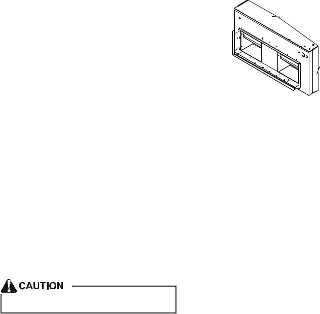
Product Identification
DAR |
Nominal Cooling Capacity |
Model Series
DAR
0904 - 90,000 Btuh (7 1/2 Tons)
1204 - 120,000 Btuh (10 Tons)
Product Description
When matched with DX11 and DZ11 condensers, this system complies with the minimum efficiency requirements found in ASHRAE 90.1-2007. See the Daikin DX11 and DZ11 specification sheets for details on these condensers. For other Daikin condenser(s) that can be matched with this airhandler to obtain ASHRAE 90.1-2007 compliance, consult with your local distributor.
The DAR series is intended for use with a room thermostat. This thermostat is not supplied with this equipment. Only thermostats that use 24 VAC control circuitry are to be used.
|
DAR0904 |
DAR1204 |
Net Weight (Lbs.) |
375 |
400 |
|
|
|
Shipping Weight (Lbs.) |
405 |
430 |
Refrigerant |
R-410A |
R-410A |
Blower Wheel (Dia x Width) |
11X10 |
11X10 |
Blower Wheel Quantity |
2 |
2 |
Motor Type |
Belt Drive |
Belt Drive |
Motor Qty |
1 |
1 |
Motor (HP) |
1 1/2 |
2 |
|
|
|
Motor (RPM) |
1750 |
1750 |
|
|
|
Motor Sheave Type |
Adjustable Variable Pitch |
|
|
|
|
Motor Sheave Diameter (in) |
1.9" - 2.9" |
2.8" - 3.8" |
Blower Wheel Pulley Type |
Fixed Diameter |
|
|
|
|
Blower Wheel Pulley Dia (in) |
5.9 |
5.9 |
Evaporator Coil Material |
Copper Tubes / Al Fins |
|
Face Area (Ft2) |
8.9 |
10.0 |
Number of Rows |
4 |
4 |
Suction Line Quantity |
1 |
2 |
Suction Line Connection (in) * |
1 1/8 |
1 1/8 |
|
|
|
Liquid Line Quantity |
1 |
2 |
Liquid Line Connection (in)* |
5/8 |
3/8 |
Metering Device |
Thermal Expansion Valve (TXV) |
|
|
|
|
TXV Type |
Non-adjustable (factory installed) |
|
|
|
|
TXV Quantity |
1 |
2 |
*Note: Consult with the condenser specifications for suction and liquid line sizing.
Unit Inspection
Upon delivery, the unit is to be inspected for damage. Any damage must be reported immediately to the carrier. Do not install this equipment if it is determined that the integrity or safety has been compromised by freight damage.
Using the table “Model Identification” section check the equipment model number to ensure the unit is appropriately sized for the condenser unit(s).
If an incorrect unit is supplied it must not be installed and it is to be returned to the supplier. The manufacturer assumes no responsibility for the installation of incorrect delivered units.
The evaporator coil contains a high-pressure inert gas holding charge.
Codes & Regulations
This product is designed and manufactured to comply with national codes. Installation in accordance with such codes and/or prevailing local codes/regulations is the responsibility of the installer. The manufacturer assumes no responsibility for equipment installed in violation of any codes or regulations.
The United States Environmental Protection Agency (EPA) has issued various regulations regarding the introduction and disposal of refrigerants. Failure to follow these regulations may harm the environment and can lead to the imposition of substantial fines. Should you have any questions please contact the local office of the EPA.
Replacement Parts
When reporting shortages or damages, or ordering repair parts, give the complete product model and serial numbers as stamped on the product. Replacement parts for this product are available through your contractor or local distributor. For the location of your nearest distributor consult the white business pages, the yellow page section of the local telephone book or contact:
CONSUMER AFFAIRS
DAIKIN NORTH AMERICA LLC
7401 SECURITY WAY
HOUSTON, TEXAS 77040 855-770-5678
If replacing an air handler, the system must be manufacturer approved and Air-Conditioning, Heating, and Refrigeration Institute (AHRI) matched. NOTE: Installation of unmatched systems is strongly discouraged.
Pre-Installation Instructions
Carefully read all instructions for the installation prior to installing product. Make sure each step or procedure is understood and any special considerations are taken into account before starting installation. Assemble all tools, hardware and supplies needed to complete the installation. Some items may need to be purchased locally. Make sure everything needed to install the product is on hand before starting.
3
Location
NOTE: Airhandlers are designed for indoor installation only.
When installing this airhandler in an enclosed area, such as a garage/parking area, as with any carbon monoxide producing device (i.e. and automobile, space heater, water heater, etc.), insure that the area is properly ventilated.
The DAR airhandler is suitable for installation in multiple locations including:
*Overhead (attic/mezzanine, etc.)
*Closet/mechanical room
When installing this airhandler, consideration is to be given to minimize the length of refrigerant tubing. Also, do not install the airhandler in a location either above or below the condenser that violates the instructions provided with the condenser.
The clearance from a combustible surface to the unit may be 0". However, service clearance is to take precedence. In addition allow a minimum of 36" in front of the unit for service clearance. Allow sufficient clearance to remove the heater elements for service or replacement in heat kits when utilized in application.
When installing in an area directly over a finished ceiling (such as an attic), an emergency drain pan is required directly under the unit. See local and state codes for additional requirements.
When installing this unit in an area that may become wet, elevate the unit with a study, non-porous material.
In installations that may lead to physical damage (warehouse, industrial sites, etc.), it is advised to install a protective barrier to prevent such damage.
Return Ductwork
DO NOT TERMINATE THE RETURN DUCTWORK IN AN AREA THAT CAN INTRODUCE TOXIC, OR OBJECTIONABLE FUMES/ODORS INTO THE DUCTWORK. The return ductwork is to be introduced into the air handler bottom (upflow configuration). The cabinet dimensions are 48” x 24”.
Return Air Filters
Each installation must include a return air filter. This unit is factory equipped with disposable return air filters. To ensure optimum performance, frequent filter replacement is advised. See the following table for the factory installed filter sizes.
Model |
Filter Size (in) |
Qty. |
|
|
|
|
|
DAR0904 |
16 x 20 x 2 |
4 |
|
|
|
|
|
DAR1204 |
16 x 20 x 2 |
2 |
|
20 x 20 x 2 |
2 |
||
|
|||
|
|
|
Ductwork
This DAR air handler is designed for a complete supply and return ductwork system.
Do not operate this product without all the ductwork attached.
To ensure correct system performance, the ductwork is to be sized to accommodate 375-425 CFM per ton of cooling with the static pressure not to exceed .5" WC. Inadequate duct work that restricts airflow can result in improper performance and compressor or heater failure. Ductwork is to be constructed in a manner that limits restrictions and maintains suitable air velocity. Ductwork is to be sealed to the unit in a manner that will prevent leakage.
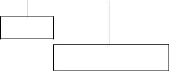
Supply Ductwork and Flanges
The supply ductwork flanges are shipped loose and required to be field installed. See the following sketch for further details: Dimensions are approximately 40" x 13-1/8".
Electric Heat
Refer to this manual in combination with the instructions provided with the heat kit for the correct installation procedure.
The electrical characteristics of the airhandler, the electric heat kit, and the building power supply must agree.
The air handlers listed in this manual do not have factory installed electric heat. Electric heat is available as an accessory. If installing this option, the ONLY heat kits that can be used are the AHKD series.
AHKD MODEL |
NOMINAL |
ELECTRICAL |
STAGES |
|
NUMBER |
KW |
CHARACTERISTICS |
||
|
||||
AHKD15-3 |
15 |
208-230/3/60 |
1 |
|
AHKD15-4 |
15 |
460/3/60 |
1 |
|
AHKD20-3 |
20 |
208-230/3/60 |
2 |
|
AHKD20-4 |
20 |
460/3/60 |
2 |
|
AHKD30-3 |
30 |
208-230/3/60 |
2 |
|
AHKD30-4 |
30 |
460/3/60 |
2 |
For all supply voltages, use the correction factors in the following tables, multiplied by KW and (or) temperature rise to have corrected results.
4
 Loading...