


INSTALLATION MANUAL
Electric heater kit
English language: Original Instructions
All other language: Translation of the Original Instruction
EEH01A6 |
|
|
EEH02A6 |
|
|
EEH03A6 |
|
|
EEH06A6 |
|
|
EEH10A6 |
Installation manual |
English |
|
Electric heater kit |
|
|
|
|
|
Installationsanleitung |
Deutsch |
|
Elektrisches Heizgerät |
|
|
|
|
|
Manuel d’installation |
Français |
|
Chauffage électrique |
|
|
|
|
|
Manual de instalación |
Español |
|
Calefactor eléctrico |
|
|
|
|
|
Manuale d’installazione |
Italiano |
|
Riscaldatore elettronico |
|
|
|
D A B C D G E F H I
+ J
1
E
J C B
|
|
|
|
|
|
|
|
|
|
|
|
|
|
2 |
|
|
3 |
|
4 |
|
5

NOTES

EEH01A6 EEH08A6 EEH02A6 EEH10A6 EEH03A6
Electric heater kit |
Installation manual |
Read this manual attentively before starting up the unit. Do not throw it away. Keep it in your files for future reference.
Improper installation or attachment of equipment or accessories could result in electric chock, short-circuit, leaks, fire or other damage to the equipment. Be sure only to use accessories made by Daikin which are specifically designed for the use with the equipment and have them installed by a professional.
If unsure of installation procedures or use, always contact your Daikin dealer for advice and information.
All field wiring and components must be installed by a licensed electrician and must comply with relevant local and national regulations.
Before installation
This is an option to be used in combination with Daikin units. Refer to the installation and operation manual of the units for installation and operation instructions.
Installation and maintenance should be carried out by technical personnel qualified for this type of machine, in compliance with current safety regulations.
When receiving the kit please check its state, verifying if any damage occurred during transport.
Identify model and version of the electrical heater series from the indications stated on the carton package.
Characteristics
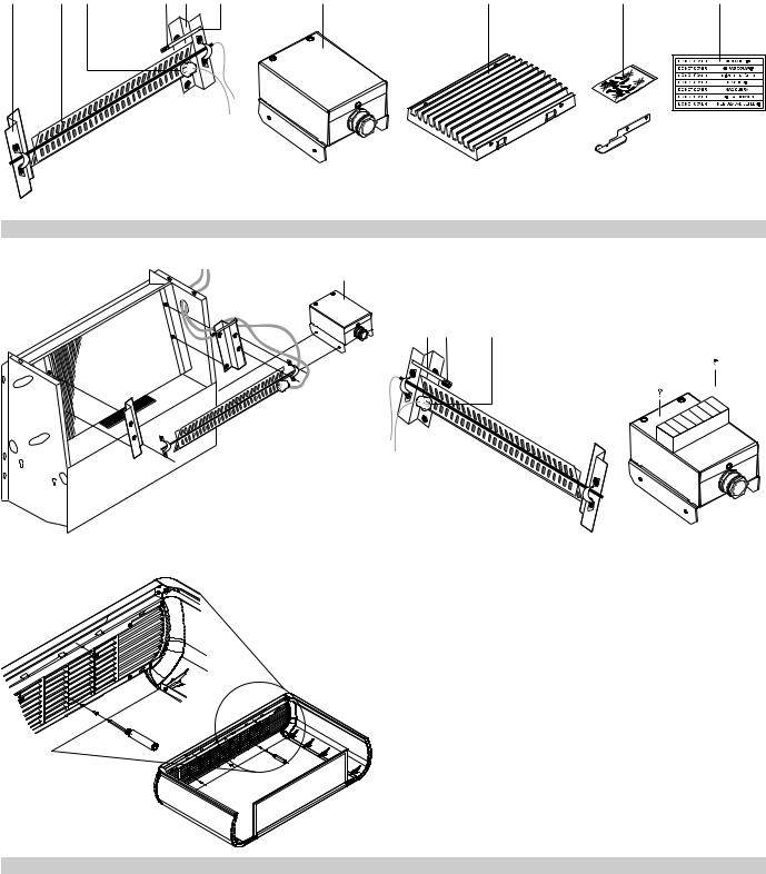
Supplied to supplement conventional hot water heating (e.g. fan coil units served by a heat pump). The optional EEH (electric heater kit) elements can be used on 2-pipe system and 3-rows heat exchanger
units ((FWV, FWL, FWM, FWZ, FWR and FWS). The kit shown in figure 1 consists of:
nElectric heater assembly made of:
A Electric heating element with finned aluminium cladding, designed for 230 V, 1-50 Hz power supply. The following table shows the power consumption (equivalent to the heating capacity) and the operating current;
|
|
|
|
Power consumption |
Operating current |
|
|
Unit |
Heater |
kW |
A |
|
|
FW01 |
EEH01 |
1.0 |
4.5 |
|
|
FW02+15 |
EEH02 |
1.5 |
6.8 |
|
|
FW03+25 |
EEH03 |
1.6 |
7.3 |
|
|
FW04+06+35 |
EEH06 |
2.0 |
9.1 |
|
|||||
|
|
FW08+10 |
EEH10 |
3.0 |
13.6 |
Bsafety thermostat with automatic reset fixed to the electric heating element, interrupting the operation in the event of overheating;
Cnon self-resetting safety switch (thermofuse) fixed to the supporting bracket, interrupting the operation only if the automatic safety thermostat fails to operate;
Dheating element brackets;
nOther elements of the kit:
E box containing electrical wiring and operating relays; F set of intermediate heat-resistant plastic grilles;
G fuse support to be used for units with water connections on the left;
H package of screws;
I sticker with the warning DO NOT COVER;
Jadditional fuse support to be used for units with water connections on the right.
The EEH heating element must be combined with one of the following controllers:
Features |
FWEC1 |
FWEC2 |
FWEC3 |
|
|
|
|
LCD Display & keys |
|
|
|
Digital inputs |
|
|
|
Water temp probe |
|
|
|
ECONOMY function on digital input |
|
|
|
4th fan speed for 4 pipes system and water |
|
|
|
valves |
|
||
|
|
|
|
Relative Humidity probe |
|
|
|
Serial communication (RS485 modbus) |
|
|
|
Display backlight |
|
|
|
Configurable digital outputs (voltage free) |
|
|
|
0-10V outputs for floating devices |
|
|
|
Clock - time zones |
|
|
|
|
|
|
|
These controllers guarantee that the heating element will work safely, thanks to the function of supplementing the hot water heating system and the post-ventilation function. Refer to the manual delivered with the dedicated controller for more information.
Installation
Important! Before obtaining access to terminals, all power circuits must be interrupted.
Proceed as follows to install the electric heater
1Remove the cabinet covering the unit, where present, and replace the existing intermediate grilles with the heat-resistant grilles supplied in the accessory kit. Figure 5 shows how to fix the heat resistant grille on the cabinet.
2Remove the front panel from wall-mounted models and the condensation tray from ceiling-mounted models.
3Install the heating element complete with its supporting brackets on the shoulders of the heat exchanger (4 fastening screws). The wires must come out on the side opposite the water connections.
4Pass the wires of the heating element and safety devices through the opening provided on the side of the base unit; make sure you first thread the wires through the bushing (see figure 2, standard configuration with water connections on the left).
If you are installing the heating element on a unit with water connections on the right, it will be necessary to change the position of the safety devices (see figure 3):
-the safety thermostat (B) must be installed on the front fin at the bottom, always on the side where the wires come out;
-the fuse (C) must be installed using the new additional fuse support (J) supplied with the kit and repositioned on the top part of the heating element, on the side where the wires come out.
Installation manual |
EEH01~10A6 |
1 |
Electric heater kit |
4PW17553-3 |

Notes on installation |
NOTES |
Each unit requires a switch (IL) on the power supply line with a distance of at least 3 mm between the opening contacts, and a suitable safety fuse (F).
The minimum wire section of the power cables are specified in the table below:
Model |
FW01 |
FW02~06 |
FW08~10 |
|
|
|
|
Gauge of power cables (mm2) |
1.5 |
2.5 |
4 |
To guarantee the efficiency of a unit equipped with a supplementary
EEH heating element, comply with the following directions:
nOn completing installation, make sure that the minimum airflow is guaranteed.
|
Minimum air flow rate |
Model |
(m3/h) |
FW01 |
196 |
FW02+15 |
232 |
FW03+25 |
265 |
FW04+35 |
397 |
FW06 |
517 |
FW08 |
627 |
FW10 |
706 |
The maximum temperature of air intake into the unit is 25°C.
nCheck the airflow rate periodically.
nDo not obstruct the air outlet or inlet of the unit in any way.
nDo not place damp or wet clothing on the air outlet grille of the unit
nDo not turn off the unit using switch IL or by cutting off power to the entire electric system. This would disable the post-ventilation function and thus the air and components in the vicinity of the heating element would risk overheating. Always use the controllers to switch off the unit.
nKeep the air filter clean.
nDo not pour liquids inside the equipment.
Operation
Refer to the manual of the controller.
|
|
|
|
|
|
|
|
EEH01~10A6 |
Installation manual |
|
|
Electric heater kit |
2 |
|
|
4PW17553-3 |
|
||
 Loading...