


Operation Manual
intelligent Touch Controller
Model
DCS601B51
●Thank you for purchasing intelligent Touch Controller.
●This operation manual contains notes for safe use of the product.
For correct use, be sure to read this manual carefully before use.
Store this manual close at hand so that it can be referred to as required.
Before use
Safety Instructions
Be sure to follow the instructions below |
1 |
use |
|
System Overview |
3 |
||
|
|||
Features and Functions |
4 |
Before |
|
Part Names and Functions |
5 |
||
|
|||
Part Names on the Monitoring |
|
|
|
Screen and the Functions |
9 |
|
|
List |
|
||
Icon |
11 |
|
|
|
|
|
|
Operation |
|
|
|
Operation |
13 |
Operation |
|
Quick Reference |
|||
|
|||
Air Conditioner Operation |
14 |
|
|
Monitoring the Operation of Air Conditioner |
22 |
|
|
System Setup Menu |
25 |
|
|
|
|
|
|
Maintenance |
56 |
Maintenance |
|
Precautions |
|
||
Maintenance |
57 |
|
|
LCD Maintenance |
|
||
When Leaving the Product |
57 |
|
|
Turned OFF for a Long Time |
|
||
Troubleshooting |
58 |
|
|
|
|
Information |
|
For Your Information |
65 |
||
|
|||
Error Diagnostic Functions |
|
||
Options |
67 |
|
|
Double intelligent Touch Controllers |
67 |
|
|
Specification |
68 |
YourFor |
|
After-sales Service |
69 |
||
|
|||
|
|
|
Use smart and save smart
We use recycled paper for making this operation manual.
Safety Instructions Be sure to follow the instructions below
Read the manual carefully in advance for correct use
Instructions given here are classified into the following two categories. Instructions in both categories are important for safety and must be duly followed.
 Warning
 Caution
Failure to follow the instruction may lead to serious consequences including death or serious injury.
Failure to follow the instruction may cause injury or material damage, which, in some cases, leads to serious consequences.
The symbol given in the manual shows the following:
Do not attempt to do things described in the instruction.
Be sure to follow the instruction.
When you have read this manual, be sure to store it in a place where the operator can conveniently refer to at anytime.
In case of personnel change, be sure to give the manual to the new operator.
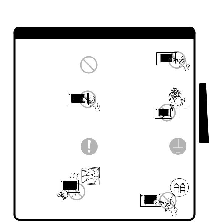
 Warning Notes on use for users
When any abnormality (such as burnt smell) is generated, turn the power OFF and contact the dealer you purchased the product from.
Continuing to operate with the abnormality left unattended may cause failure, electric shock or fire.
For remodelling or repair, contact the dealer you purchased the product from.
Failure to remodel or repair properly may cause water leak, electric shock or fire.
For transferring or reinstallation, contact the dealer you purchased the product from.
Failure to install properly may cause water leak, electric shock or fire.
Do not touch the inside of the controller.
Do not remove the front panel. Touching the inside is dangerous
and may cause failure. For inspection and adjustment
of the inside of the controller, contact the dealer you purchased the product from.
1
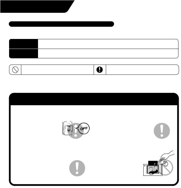
 Caution Notes on use for users
Be sure to operate with the touch pen provided.
Failure to follow the instruction may lead to damage or failure.
To clean, be sure to stop operation and turn the power OFF.
Failure to follow the instruction may lead to electric shock or injury.
Do not install in a place subject to flammable gas.
Leakage of gas resulting in accumulation around the unit may lead to ignition.
Do not install in a place subject to direct sunlight.
Failure to follow the instruction may lead to discoloring of the LCD that hinders proper display. 
Do not wash the controller with water.
Washing may lead to electric shock.
Do not install the controller in a place subject to water.
Water in the device may lead to electrical leak and failure in the electronic components inside.
Be sure to provide grounding.
Do not connect the grounding wire to any gas pipe, water pipe, lightning rod or telephone grounding.
Inappropriate grounding may lead to electric shock.
Do not wipe the surface of the controller touch panel with benzine, thinner or chemicallytreated dust cloth.
Failure to follow the instruction may lead to discoloring or peeling of the
paint. Any soiling must be wiped off
benzine thinner
with a piece of cloth soaked in a diluted neutral
detergent and
wrung sufficiently. Wipe again with a
dry piece of cloth.
Before use
2
System Overview
This intelligent Touch Controller is capable of controlling/monitoring up to 64 groups of indoor units (hereafter “groups”).
The main functions of the intelligent Touch Controller include:
1.Collective starting/stopping of operation of the indoor units connected to the intelligent Touch Controller.
2.Starting/stopping of operation, temperature setting, switching between temperature control modes and enabling/disabling of operation with the hand-held remote control by zone or group .
3.Scheduling by zone or group .
4.Monitoring of the operation status by zone or group .
5.Display of the air conditioner operation history.
6.Compulsory contact stop input from the central monitoring panel (non-voltage, normally-open contact).
7.Power distribution of the air conditioners. (With the optional DCS002A51)
A group of indoor units include:
q One indoor unit without a remote control. w One indoor unit controlled with one or two remote controls.
|
Indoor unit |
|
|
No remote control |
|
or |
|
Remote control |
Remote control |
||
|
e Up to 16 indoor units controlled with one or two remote controls.
Remote control |
Up to 16 units |
Two remote controls |
Up to 16 units |
Zone control with the intelligent Touch Controller
Zone control, which allows collective settings for more than one group, is available with the intelligent Touch Controller, which facilitates the setting operations.
Zone 1 |
Zone 2 |
Zone 3 |
Zone 4 |
intelligent Touch Controller
Zone 5
•One setting makes the same setting for all of the units in one zone.
•Up to 128 zones can be set with one intelligent Touch Controller. (The maximum number of groups in one zone is 64.)
•Groups can be zoned at will with the intelligent Touch Controller.
•Units in one group can be divided into more than one zone.
3
Features and Functions
Operation Menu
intelligent Touch Controller is capable of starting/stopping of the operation by the group or zone. Collective starting/stopping is also available.
Air Conditioner Detail Setup
Temperature setting, switching between temperature control modes, switching of speed and direction of wind and remote control mode setting are available by the group, by the zone or collectively.
Monitoring of Various Information on Indoor Units
Information on operation such as the operation mode and temperature setting of the indoor units, maintenance information including the filter or element cleaning sign, troubleshooting information such as error codes can be displayed by the group or the zone.
Diversified Operation Modes
Operation can be controlled both with the main unit and the remote control to provide diversified operation management. Setting with the main unit allows the following remote control settings by the group, by the zone or collectively:
1. Start/Stop |
2. Operation Mode |
3.Temperature Setting |
:(Remote control) Inhibited |
:(Remote control) Inhibited |
:(Remote control) Inhibited |
:(Remote control) Permitted :(Remote control) Permitted :(Remote control) Permitted
:Priority
Zone Control Simplifying Complicated Setting Operations
Up to 64 groups can be controlled with the intelligent Touch Controller.
More than one group can be consolidated into a zone, which can be registered, to allow the following settings by the zone. This eliminates the need for repeating the same setting operation for each group. Function to allow collective setting for all groups is also available.
•Start/stop
•Temperature setting
•Switching between operation modes
•Setting of direction and fan speed
•Disabling/enabling the remote control
Detailed Scheduled Operation Control
The intelligent Touch Controller allows detailed scheduled operation by the group, by the zone or collectively. Up to 8 options for annual schedule can be set. Each schedule can include four types of plans: for Weekdays, Holidays, Special days 1 and Special days 2. Each of the plans allows setting of up to 16 operations.
Handy Automated Control
The Intelligent Touch Controller can do the following.
• Change Over Settings: automatically switches between cooling and heating according to the room temperature.
• Temperature Limit Settings: prevents the temperature from rising too high or too low in unmanned rooms.
• Heating Optimization Settings: stops uncomfortable hot air from blowing when the heating thermo is off.
See pages
14 to 16
See pages
17 to 21
See pages
22 to 24
See page 21
See pages
14 to 24
26
See pages
27 to 28
See pages
29 to 38
Before use
4
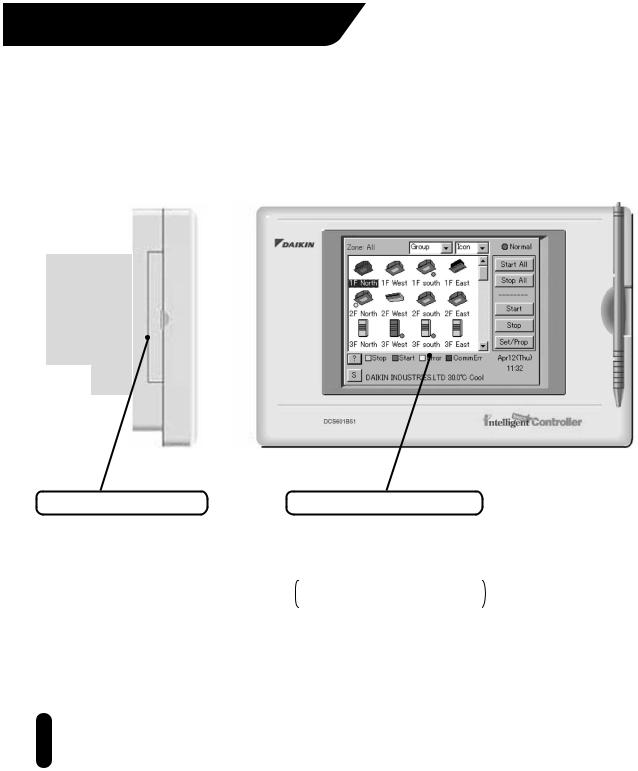
Part Names and Functions
PCMCIA Card Slot |
Color LCD with Touch Panel |
Used when using the optional power distribution (DCS002A51) or updating the intelligent Touch Controller software to a newer version.
Provides a display for monitoring and operation.
Be sure to use the touch pen provided for operation.
The display shows the Monitoring and System Setup screens.
Note
 Be sure to use the touch pen for operation of the touch panel of the intelligent Touch Controller. Operating with an object other than the touch pen provided may cause damage and failure.
5
Touch Pen
Use the touch pen for operation. Be sure to use the touch pen for operation.
Use caution not to lose the touch pen.
When the pen is lost, contact the dealer you purchased the product from.
Before use
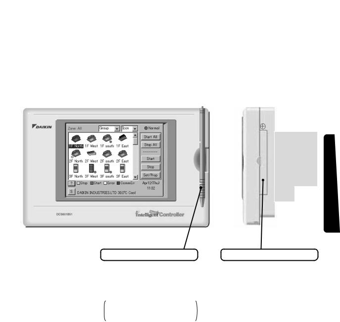
Maintenance Door
Generally not used. Close the door for general use.
Use the door when adjusting the contrast of the LCD or luminance of the backlight.
6
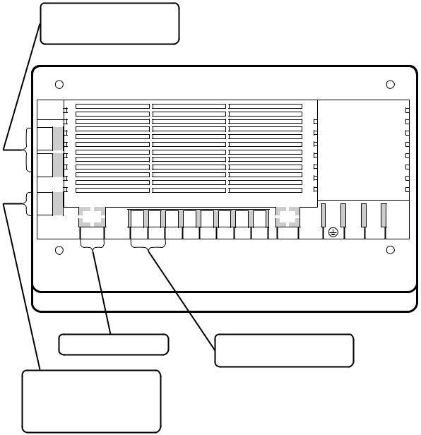
Terminals on the Back of intelligent Touch Controller
Use these ports for modem communication when using the AIRNET Service.
CN2 2-232C 1-232C
Ethernet |
COM Dil Pi3 COM Pi2 Pi1 F2 F1 |
LON |
L2 L1 |
This port is not used with this model.
Connect the collective remote control adapter to this connector for “collective start of operation,” “collective stop of operation” or “error monitoring” remotely with a contact signal.
Connect a non-voltage contact for collective stopping of operation with a contact signal.
7
Before use
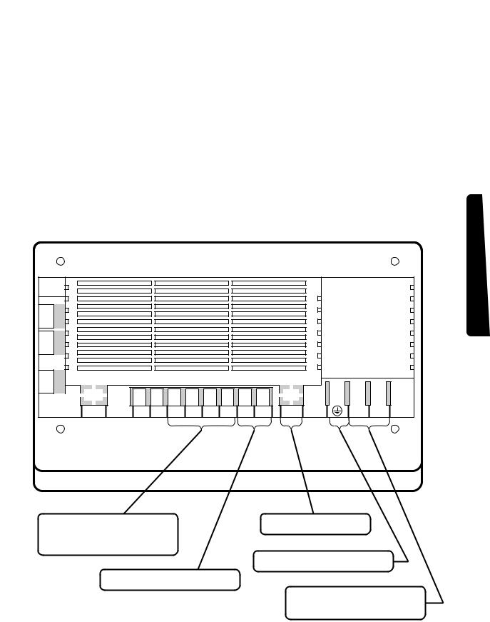
CN2 2-232C 1-232C
Ethernet |
COM Dil Pi3 COM Pi2 Pi1 F2 F1 |
LON |
L2 L1 |
Connect a watt-hour meter when using the optional power distribution function software (DCS002A51).
Terminals for communication with air conditioning system.
This port is not used with this model.
Terminal for the grounding wire.
Terminals for the power supply. Connect single-phase power of 100 to 240 VAC, 50/60 Hz.
8

Part Names on the Monitoring Screen and the Functions
List
Contents of the List Currently Displayed
•When Group List is displayed “Zone: Zone Name”
•When Zone List is displayed “Zone List”
Filter/Element Sign
Displayed when there is any air conditioner showing a filter or element sign in the zone or the group.
Zone/Group Name
Set the names in the Group Registration or Zone Registration in the System Setup Mode.
Target of Automatic Control
Displayed when there is any air conditioner with the registration of scheduled or change over or temperature limit or heating mode optimization operation in the zone or in the group.
Monitoring Screen Legend
Pressing the “?” button shows more detailed legend.
Description of Zone/Group
Set the names in the Group Registration or Zone Registration in the System Setup Mode.
Button to Switch to the System Setup Mode
Use this button for settings including the time, group, zone and schedule.
System Status Display Area
Area for displaying the system status (compulsory stop, etc.).
Display Mode Selection
Select between Zone and Group.
Zone/Group Currently Displayed
The name of the zone/group currently selected is highlighted.
Information on Zone/Group Currently Displayed
Generally, the temperature setting and the operation mode are displayed.
If any error occurs in the air conditioner, the error code is displayed.
9
Display Type Selection
Select the type between Icon and List.
The example below shows the List Display. For Icon Display, see pages 11,12 .
Scroll Bars
Use the bars to monitor any area of the group/zone list not currently shown.
Sliding the bars up/down and left/right changes the range monitored.
Display for Collective Monitoring of Air
Conditioners Connected to intelligent Touch Controller
When operation is normal and any air conditioner is in operation:
Red/Normal
When operation is normal and all air conditioners are in stoppage:
Green/Normal
When there is any air conditioner generating an error:
Yellow/Abnormal
When there is any air conditioner with communication error:
Blue/Abnormal
Start All Button
Button to collectively start all the air conditioners connected to intelligent Touch Controller.
Stop All Button
Button to collectively stop all the air conditioners connected to intelligent Touch Controller.
Group/Zone Start Button
Button to start operation of the group/zone selected.
Group/Zone Stop Button
Button to stop operation of the group/zone selected.
Group/Zone Set/Prop Button
Makes detailed settings (temperature setting, temperature control mode, etc.) and display of the group/zone selected.
Current Time Display
Shows the current date and time.
Before use
10
 Loading...