


Daikin DWSC 079, DWSC 087, DWSC 100, DWSC 113, DWSC 126 Operation manuals
...REV |
09 |
Date |
January 2020 |
Supersedes |
D-EIMC00808-16_08EN |
|
|
Installation, Operation and Maintenance Manual
D-EIMWC00808-16_09EN
Original Instructions
Single/Dual Compressor Centrifugal Chillers – Vintage B
DWSC/DWDC 079, 087, 100, 113, 126, Cooling Only

 IMPORTANT
The units described in the present manual represent a valuable investment. Maximum care should be taken to ensure correct installation and appropriate working conditions of the units.
THIS MANUAL, WIRING DIAGRAMS AND DIMENSIONAL DRAWINGS MUST BE CONSIDERED ESSENTIALS, KEEP A COPY OF THESE DOCUMENTS ALWAYS AVAILABLE INSIDE THE UNIT.
Installation and maintenance must be performed by qualified and specifically trained personnel only.
Correct maintenance of the unit is indispensable for its safety and reliability. Manufacturer’s service centres are the only having adequate technical skill for maintenance.
The unit is made of metal, plastic and electronic parts. All of these components must be disposed of in accordance with local disposal laws and if in scope with the national laws implementing the Directive 2012/19/EU (RAEE).
Lead batteries must be collected and sent to specific waste collection centres.
Avoid the escape of refrigerant gases into the environment by using suitable pressure vessels and tools for transferring the fluids under pressure. This operation must be carried out by qualified personnel in refrigeration systems and in compliance with the laws in force in the country of installation.
 IMPORTANT
READ THIS DOCUMENT IN ITS ENTIRETY BEFORE BEGINNING ANY WORK ON THE UNIT. ALL FEDERAL, STATE, LOCAL ENVIRONMENTAL AND SAFETY REGULATIONS INCLUDING DAIKIN
SAFETY RULES MUST BE FOLLOWED.
All appropriate Personal Protective Equipment (“PPE”) must be used, and a Job Hazard Analysis (“JHA”) must be completed, before beginning any work on the unit.
Technicians performing this work must be properly trained on Daikin WSC, WDC, DWSC, DWDC Centrifugal equipment.
Important Note: In case of any procedure requires accessing the refrigerant circuit of these units, remember that refrigerant is under pressure and oils are contained in these circuits.
Ensure that all appropriate pump-down or pump-out service valves are in the correct position, open or closed as required and holding.
Solenoid valves and expansion valves can trap refrigerant and oils, these devices must be operated manually to release any trapped gases and oils while in pump-down or pump-out operation.
All refrigerant lines and components of the unit must be evacuated to at least 30 kPa vacuum and verified before opening any charging valves, venting schrader valves or testing ports.
These devices must be open and vented while accessing the refrigerant system. In some cases, cross connection lines may be required to ensure recovery of all refrigerant in all sections of the affected system or components.
D–EIMWC00808-16HU - 3/64

 CAUTION
All units are delivered from factory as complete sets which include wiring diagrams and dimensional drawings with size, weight and features of each model.
In case of any discrepancy between this manual and the two aforesaid documents, please refer to the wiring diagram and dimensional drawings.
Power Wiring
•Qualified and licensed electricians must perform wiring. Shock hazard exists.
•Connections to terminals must be made with copper lugs and copper wire.
•Before any installation and connection work, the system must be switched off and secured. After switching off the unit, when an inverter is installed, the intermediate circuit capacitors of the inverter are still charged with high voltage for 5 minutes.
•Before taking any action, switch off the main switch to cut off electricity to the machine.
When the machine is off but the disconnecting switch is in the closed position, unused circuits are always live. Never open the terminal board box of the compressors unless the main switch of the machine has been switched off.
•The units of the series can be provided with non-linear high power electrical components (inverters) which introduce higher harmonics, can cause considerable leakage to earth, (higher than 300 mA). The electricity supply system protection must take the above values into account.
WARNING
Before starting the installation of the unit, please read this manual carefully. Starting up the unit is absolutely forbidden if all instructions contained in this manual are not clear.
•Commissioning of the unit (first start up) must be performed by Daikin representative
•It is absolutely forbidden to remove all the protections of the moving parts of the unit
•If the unit mounts suction and discharge valves they need to be secured in open position when the unit is installed, by means of a lead seal or equivalent. This to avoid they are put in closed position. The use of this valve is intended for compressor maintenance.
•If refrigerant charge of the unit is more than 500 kg it is necessary to install gas sensor on water circuit to catch an eventual gas leakage.
•Verify that the unit has not zero pressure in the refrigerant circuit before charging water into the heat exchangers. In case there is not pressure in the refrigerant circuit, do not charge water.
•Do not use oxygen or a mixture of R-22 and air to build up pressure as explosion can occur causing serious personal injury.
Warnings for the operator
The operator must read this manual before using the unit.
The operator must be trained and instructed on how to use the unit.
The operator must strictly follow local safety regulation and laws.
D–EIMWC00808-16HU - 4/64

The operator must strictly follow all instruction and limitation given for the unit.
The operator is not authorized to perform maintenance. Maintenance has to be performed only by trained technicians, please contact DAIKIN representative.
The operator must apply all the safety standard regarding personal protective equipment and working tools.
Key to symbols
Important note: failure to respect the instruction can damage the unit or compromise functioning
Note regarding safety in general or respect of laws and regulations
Note concerning electrical safety
 Note concerning pressure equipment
Safe use and maintenance of the unit, as explained in this manual, is fundamental to prevent accidents during operation and maintenance and repair work.
Therefore, it is highly recommended that this document be read carefully, complied with and stored safely.
D–EIMWC00808-16HU - 5/64
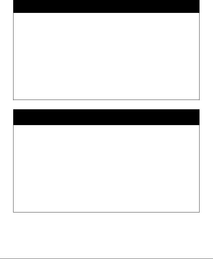
Description of the labels applied to the electrical panel
Compressor Starter Panel
1 – Manufacturer’s logo |
3 – Cable tightening warning |
2 – Hazardous Voltage warning |
4 – Electrical hazard symbol |
|
|
|
|
|
|
|
|
|
|
8 |
|
|
|
|
|||||||
|
|
Unit Control Panel |
|||||||||||||||||||
1 – Non flammable gas symbol |
|
|
|
|
|
5 – Unit nameplate data |
|||||||||||||||
2 – Electrical hazard symbol |
|
|
|
6 – Unit characteristics technical |
|||||||||||||||||
3 – Gas type |
|
|
|
|
|
|
|
7 – Emergency stop |
|||||||||||||
4 – Control panel code |
|
|
|
|
|
8 – Label: unit under pressure |
|||||||||||||||
|
|
|
|
|
|
|
|
|
|
|
|
|
|
|
|
|
|
|
|
|
|
|
|
|
|
|
|
|
|
|
|
|
|
|
|
|
|
|
|
|
|
|
|
|
|
|
|
|
|
|
|
|
|
|
|
|
|
|
|
|
|
|
|
|
|
|
|
|
|
|
|
|
|
|
|
|
|
|
|
|
|
|
|
|
|
|
|
|
|
|
|
|
|
|
|
|
|
|
|
|
|
|
|
|
|
|
|
|
|
|
|
|
|
|
|
|
|
|
|
|
|
|
|
|
|
|
|
|
|
|
|
|
|
|
|
|
|
|
|
|
|
|
|
|
|
|
|
|
|
|
|
|
|
Compressor Control Panel
|
1 – Components layout |
3 – Electrical hazard symbol |
|
|
2 – Hazardous Voltage warning |
4 – Compressor control panel code |
|
|
|
|
|
|
|
|
|
|
|
D–EIMWC00808-16HU - 6/64 |
|

Motor Terminal Box
1 – Terminal box fixing |
3 – Electrical hazard symbol |
2 – Manufacturer’s logo |
4 – Terminal connection |
1
Label on Compressor
1 – Label: Device Under Pressure
D–EIMWC00808-16HU - 7/64

Table of Contents |
|
Warnings for the operator ....................................................................................... |
Errore. Il segnalibro non è definito. |
Introduction .................................................................................................................................... |
10 |
General Description ........................................................................................................................................................ |
10 |
Application ..................................................................................................................................................................... |
10 |
Nomenclature.................................................................................................................................................................. |
10 |
Installation ...................................................................................................................................... |
11 |
Receiving and Handling ................................................................................................................................................. |
11 |
Location and Mounting................................................................................................................................................... |
12 |
Operating/Standby Limits............................................................................................................................................... |
12 |
Safety .............................................................................................................................................................................. |
13 |
System Water Volume ..................................................................................................................................................... |
14 |
Low Condenser Water Temperature Operation............................................................................................................... |
14 |
Water Piping ................................................................................................................................................................... |
16 |
Field Insulation Guide .................................................................................................................................................... |
20 |
Physical Data and Weights.............................................................................................................................................. |
22 |
Oil Coolers...................................................................................................................................................................... |
23 |
Oil Heater ....................................................................................................................................................................... |
26 |
Relief Valves ................................................................................................................................................................... |
27 |
Electrical ......................................................................................................................................................................... |
28 |
Power Wiring .................................................................................................................................................................. |
28 |
Remote Starter Display Wiring....................................................................................................................................... |
30 |
Control Power Wiring..................................................................................................................................................... |
30 |
Multiple Chiller Setup .................................................................................................................................................... |
35 |
Prestart System Checklist ............................................................................................................................................... |
38 |
Operation ........................................................................................................................................ |
39 |
Operator Responsibilities................................................................................................................................................ |
39 |
Standby Power ................................................................................................................................................................ |
39 |
MicroTech II Control .................................................................................................................................................. |
39 |
Capacity Control System ................................................................................................................................................ |
40 |
Surge and Stall ................................................................................................................................................................ |
43 |
Lubrication System ......................................................................................................................................................... |
43 |
Hot Gas Bypass .............................................................................................................................................................. |
44 |
Condenser Water Temperature ........................................................................................................................................ |
45 |
Maintenance ................................................................................................................................... |
46 |
Pressure/Temperature Chart............................................................................................................................................ |
46 |
Routine Maintenance ...................................................................................................................................................... |
47 |
Annual Shutdown ........................................................................................................................................................... |
51 |
Annual Startup ................................................................................................................................................................ |
52 |
Repair of System ............................................................................................................................................................ |
52 |
Oil Analysis .................................................................................................................................................................... |
56 |
Maintenance Schedule ................................................................................................................... |
59 |
Service Programs ........................................................................................................................... |
62 |
Operator Schools............................................................................................................................ |
63 |
Warranty Statement ...................................................................................................................... |
64 |
Important information regarding the refrigerant used.............................................................. |
65 |
Information and illustrations cover the Daikin products at the time of publication and we reserve the right to make changes in design and construction at anytime |
|
without notice. |
|
|
D–EIMWC00808-16HU - 8/64 |

D–EIMWC00808-16HU - 9/64

Introduction
General Description
Daikin Centrifugal Water Chillers are complete, self-contained, automatically controlled fluid chilling units. Each unit is completely assembled and factory tested before shipment. Models DWSC/DWDC are cooling-only.
In the DWSC, each unit has one compressor connected to a condenser and evaporator. The DWDC series is equipped with two compressors operating in parallel on a single evaporator and condenser. Information in this manual referring to all DWSC and DWDC units except where specifically noted.
The chillers use refrigerant R-134a (or R513A) to reduce the size and weight of the package compared to negative pressure refrigerants, and since these refrigerants operates at a positive pressure over the entire operation range, no purge system is required.
The controls are pre-wired, adjusted and tested. Only normal field connections such as piping, electrical and interlocks, etc. are required, thereby simplifying installation and increasing reliability. Most necessary equipment protection and operating controls are factory installed in the control panel.
The basic sizes of units are the 079, 087, 100, 113 and 126. They provide a cooling capacity range from 80 tons to 2500 tons. In this manual all references to the DWSC models will equally apply to other models unless specifically referenced otherwise.
Application
The procedures presented in this manual apply to the standard DWSC/DWDC family of chillers. Refer to the Operating Manual, OM CentrifMicro II (latest version available on www.daikineurope.com), for details on operation of the MicroTech II unit controller.
All Daikin centrifugal chillers are factory tested prior to shipment and must be initially started at the job site by a factory trained Daikin service technician. Failure to follow this startup procedure can affect the equipment warranty.
The standard limited warranty on this equipment covers parts that prove defective in material or workmanship. Specific details of this warranty can be found in the warranty statement furnished with the equipment.
Cooling towers used with Daikin centrifugal chillers are normally selected for maximum condenser inlet water temperatures between 75°F and 90°F (24°C and 32°C). Lower entering water temperatures are desirable from the standpoint of energy reduction, but a minimum does exist.
Nomenclature
|
D W D C 079 |
D = Daikin |
Chiller Model, Based on |
W = Water-cooled |
Impeller Diameter |
|
|
D = Dual Compressor |
Centrifugal Compressor |
|
|
S = Single Compressor |
|
D–EIMWC00808-16HU - 10/64
Installation
Receiving and Handling
The unit should be inspected immediately after receipt for possible damage.
All Daikin centrifugal water chillers are shipped FOB factory and all claims for handling and shipping damage are the responsibility of the consignee.
Insulation corners from the evaporator's rigging hole locations are shipped loose and should be glued in place after the unit is finally placed. Neoprene vibration pads are also shipped loose. Check that these items have been delivered with the unit.
If so equipped, leave the shipping skid in place until the unit is in its final position. This will aid in handling the equipment.
Extreme care must be used when rigging the equipment to prevent damage to the control panels or refrigerant piping. See the certified dimension drawings included in the job submittal for the center of gravity of the unit. Consult the local Daikin sales office for assistance if the drawings are not available.
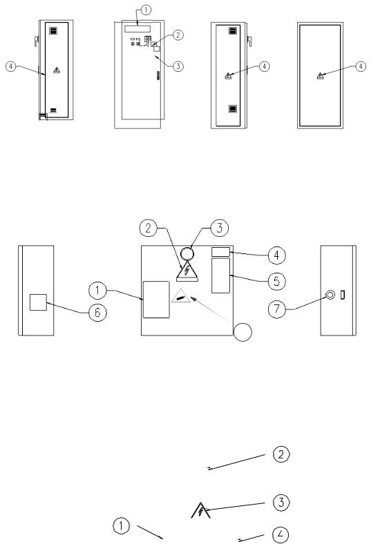
The unit can be lifted by fastening the rigging hooks to the four corners of the unit where the rigging eyes are located (see Figure 1). Spreader bars must be used between the rigging lines to prevent damage to the control panels, piping and motor terminal boxes.
|
|
Figure 1, DWSC Major Component Locations |
|
Operator Interface |
||||
|
|
|
|
|
|
|
||
|
|
|
|
|
|
|
Panel |
|
|
|
|
|
|
Unit Control |
|
|
|
|
|
|
|
|
|
|
Rigging |
|
|
|
|
|
|
Panel |
|
|
|
|
|
Compressor Control |
|
|
||||
|
|
|
|
|
Locations |
|||
|
|
Panel, At Rear |
|
|
|
|||
|
|
|
|
|
(6) Available |
|||
|
|
|
|
|
|
|
|
|
|
|
|
|
|
|
|
|
|
|
|
|
|
|
|
|
||
|
|
Rigging |
|
|
|
|
|
|
|
|
Locations |
|
|
|
|
|
|
|
|
(6) Available |
|
|
|
|
|
|
|
|
|
|
|
|
|
||
|
|
|
|
|
|
|
|
|
|
|
|
|
|
|
|
|
|
|
Evaporator |
|
|
|
|
|
|
|
|
|
|
|
|
|
|
|
|
Compressor Starter,
Mounting Optional
Condenser
D–EIMWC00808-16HU - 11/64
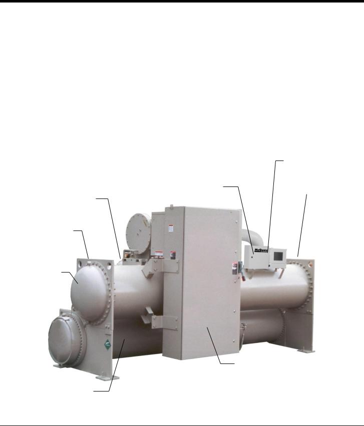
Figure 2, DWDC Major Component Location
Note: 1. Chilled water and condenser connection location can vary. Check markings on unit or consult unit certified drawings for connection locations on specific units.
Location and Mounting
The unit must be mounted on a level concrete or steel base and must be located to provide service clearance at one end of the unit for possible removal of evaporator tubes and/or condenser tubes. Evaporator and condenser tubes are rolled into the tube sheets to permit replacement if necessary. The length of the vessel should be allowed at one end. Doors or removable wall sections can be utilized for tube clearance. Minimum clearance at all other points, including the top, is 3 feet (1 meter). The National Electric Code (NEC) can require four feet or more clearance in and around electrical components and must be checked.
Operating/Standby Limits
Equipment room temperature, standby
•Water in vessels and oil cooler: 32 F to 122 F (0 C to 50 C)
•Without water in vessels and oil cooler: 0 F to 140 F (-18 C to 60 C) 55°C
•WSC without water in vessels: 0 F to 130 F (-18 C to 54.4 C)
Equipment room temperature, operating: 32 F to 104 F (0 C to 40 C)
Maximum entering condenser water temperature, startup: design plus 5 degrees F (2.7 degrees C) Maximum entering condenser water temperature, operating: job specific design temperature
D–EIMWC00808-16HU - 12/64

Minimum entering condenser water temperature, operating: see page 14.
Minimum leaving chilled water temperature: 38 F (3.3 C)
Minimum leaving chilled fluid temperature with correct anti-freeze fluid: 15 F (9.4 C)
Maximum entering chilled water temperature, operating: 90 F (32.2 C)
Maximum oil cooler/VFD entering temperature: 90 F (32.2 C)
Minimum oil cooler/VFD entering temperature: 42 F (5.6 C)
Vibration Pads
The shipped-loose neoprene vibration pads should be located under the corners of the unit (unless the job specifications state otherwise). They are installed to be flush with the sides and outside edge of the feet. Most DWSC units have six mounting feet although only the outer four are required. Six pads are shipped and the installer can place pads under the middle feet if desired.
Mounting
Make sure that the floor or structural support is adequate to support the full operating weight of the complete unit.
It is not necessary to bolt the unit to the mounting slab or framework; but should this be desirable, 1 1/8" (28.5 mm) mounting holes are provided in the unit support at the four corners.
Note: Units are shipped with refrigerant and oil valves closed to isolate these fluids for shipment. Valves must remain closed until start-up by the Daikin technician.
Nameplates
There are several identification nameplates on the chiller:
•The unit nameplate is located on the side of the Unit Control Panel. It has a Style No. XXXX and Serial No. XXXX, both are unique to the unit and will identify it. These numbers should be used to identify the unit for service, parts, or warranty questions. This plate also has the unit refrigerant charge.
•Vessel nameplates are located on the evaporator and condenser. Along with other information, they have a National Board Number (NB) and a serial number, either of which identify the vessel (but not the entire unit).
•A compressor nameplate is located on the compressor itself and contains identification numbers.
Safety
The machine must be firmly secured to the ground.
It is essential to observe the following instructions:
-The machine must be raised only by the lifting points. Only these points can support the whole weight of the unit.
-Do not allow unauthorised and/or unqualified personnel to access the machine.
-It is forbidden to access the electrical components without having opened the machine's general disconnecting switch and switched off the power supply.
-It is forbidden to access the electrical components without using an insulating platform. Do not access the electrical components if water and/or moisture are present.
-All operations on the refrigerant circuit and on components under pressure must be carried out by qualified personnel only.
-Replacement of a compressor or addition of lubricating oil must be carried out by qualified personnel onlySharp edges can cause wounds. Avoid direct contact.
-Avoid introducing solid bodies into the water pipes while the machine is connected to the system.
-A mechanical filter must be installed on the water pipe connected to the heat exchanger inlet.
-The machine is supplied with safety valves, that are installed on both the high and the low pressure sides of the refrigerant circuit.
D–EIMWC00808-16HU - 13/64

WARNING
If the unit mounts suction and discharge valves they need to be secured in open position when the unit is installed, by means of a lead seal or equivalent. This to avoid they are put in closed position. The use of this valve is intended for compressor maintenance.
In case of sudden stop of the unit, follow the instructions on the Control Manual Operating Manual which is part of the on-board documentation delivered to the end user with this manual.
It is recommended to perform installation and maintenance with other people. In case of accidental injury or unease, it is necessary to:
- keep calm |
|
- press the alarm button if present in the installation site |
|
- move the injured person in a warm place far from the unit and in rest position |
|
- contact immediately emergency rescue personnel of the building or if the Health Emergency |
Service |
- wait without leaving the injured person alone until the rescue operators come |
|
- give all necessary information to the the rescue operators |
|
System Water Volume
All chilled water systems need adequate time to recognize a load change, respond to that load change and stabilize, without undesirable short cycling of the compressors or loss of control. In air conditioning systems, the potential for short cycling usually exists when the building load falls below the minimum chiller plant capacity or on close-coupled systems with very small water volumes.
Some of the things the designer should consider when looking at water volume are the minimum cooling load, the minimum chiller plant capacity during the low load period and the desired cycle time for the compressors.
Assuming that there are no sudden load changes and that the chiller plant has reasonable turndown, a rule of thumb of
“gallons of water volume equal to two to three times the chilled water gpm flow rate” is often used.
A properly designed storage tank should be added if the system components do not provide sufficient water volume.
Low Condenser Water Temperature Operation
When ambient wet bulb temperature are lower than design, the condenser water temperature can be allowed to fall. Lower temperatures will improve chiller performance.
Daikin centrifugal chillers all across the range are equipped with electronic expansion valves (EXV) and will start and run with entering condenser water temperatures as low as shown in Figure 3 or as calculated from the following equation on which the curves are based.
D–EIMWC00808-16HU - 14/64
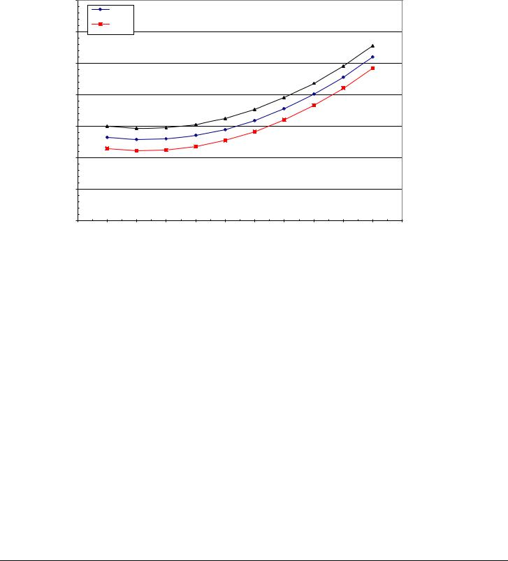
Figure 3, Minimum Entering Condenser Water Temperature (EXV)
Minimum Entering Condenser Water Temperature - 10 F Range
65,0 |
|
|
|
|
|
|
|
|
|
|
|
|
|
44 |
|
|
|
|
|
|
|
|
|
|
|
LChWT |
|
|
|
|
|
|
|
|
|
|
|
42 |
|
|
|
|
|
|
|
|
|
60,0 |
|
LChWT |
|
|
|
|
|
|
|
|
|
55,0 |
|
|
|
|
|
|
|
|
|
|
|
50,0 |
|
|
|
|
|
|
|
|
|
|
|
| <![if ! IE]> <![endif]>ECWT,F |
|
|
|
|
|
|
|
|
|
|
|
45,0 |
|
|
|
|
|
|
|
|
|
|
|
40,0 |
|
|
|
|
|
|
|
|
|
|
|
35,0 |
|
|
|
|
|
|
|
|
|
|
|
30,0 |
|
|
|
|
|
|
|
|
|
|
|
0 |
10 |
20 |
30 |
40 |
50 |
60 |
70 |
80 |
90 |
100 |
110 |
Percent Load
Min. ECWT = 5.25 + 0.88*(LWT) - DTFL*(PLD/100) + 22*(PLD/100)2
•ECWT = Entering condenser water temperature
•LWT = Leaving chilled water temperature
•DTFL = Chilled Water Delta-T at full load
•PLD = The percent chiller load point to be checked
For example; at 44 F LWT, 10 degree F Delta-T, and 50% full load operation, the entering condenser water temperature could be as low as 44.5 F. This provides excellent operation with water-side economizer systems.
Depending on local climatic conditions, using the lowest possible entering condenser water temperature may be more costly in total system power consumed than the expected savings in chiller power would suggest, due to the excessive fan power required.
Cooling tower fans must continue to operate at 100% capacity at low wet bulb temperatures. As chillers are selected for lower kW per ton, the cooling tower fan motor power becomes a higher percentage of the total peak load chiller power.
Even with tower fan control, some form of water flow control, such as tower bypass, is recommended.
Figure 5 illustrates two temperature actuated tower bypass arrangements. The “Cold Weather” scheme provides better startup under cold ambient air temperature conditions. The check valve may be required to prevent entraining air at the pump inlet.
D–EIMWC00808-16HU - 15/64
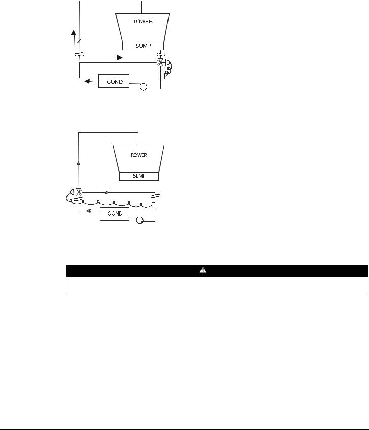
Figure 4, Bypass, Cold Weather Operation
Figure 5, Bypass, Mild Weather Operation
Water Piping
WARNING
If refrigerant charge of the unit is more than 500 kg it is necessary to install gas sensor on water circuit to catch an eventual gas leakage.
Water Pumps
Avoid the use of 3600/3000-rpm (two-pole motor) pump motors. It is not uncommon to find that these pumps operate with objectionable noise and vibration.
It is also possible to build up a frequency beat due to the slight difference in the operating rpm of the pump motor and the Daikin centrifugal motor. Daikin encourages the use of 1750/1460 rpm (four-pole) pump motors.
Vessel Drains at Start-up
Unit vessels are drained of water in the factory and are shipped with the drain plugs in the heads removed and stored in the control panel or with open ball valves in the drain hole. Be sure to replace plugs or close the valves prior to filling the vessel with fluid.
D–EIMWC00808-16HU - 16/64
Evaporator and Condenser Water Piping
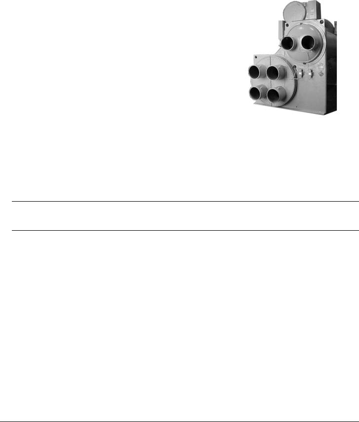
All evaporators and condensers come standard with Victaulic AWWA C-606 groove nozzles (also suitable for welding), or optional flange connections. The installing contractor must provide matching mechanical connections or transitions of the size and type required. A heat recovery chiller, DHSC, (shown on the right) has two sets of condenser piping; one for the tower, one for the heating system.
The tower connections are always the inboard pair of connections. In the figure to the right, the condenser connections are “left-hand” when viewed from the front of the unit (Unit Control Panel and Interface Panel side), so in this case, the right-hand condenser connections would be for the tower.
If the condenser connections were on the other end (“right-hand”), the tower connections would be the left-hand pair of
Important Note on Welding
If welding is to be performed on the mechanical or flange connections, remove
the solid-state temperature sensor and thermostat bulbs from the wells to prevent damage to those components. Also properly ground the unit or severe damage to the MicroTech II unit controller can occur.
Water pressure gauge connection taps and gauges must be provided in the field piping at the inlet and outlet connections of both vessels for measuring the water pressure drops. The pressure drops and flow rates for the various evaporators and condensers are job specific and the original job documentation can be consulted for this information. Refer to the nameplate on the vessel shell for identification.
Be sure that water inlet and outlet connections match certified drawings and stenciled nozzle markings. The condenser is connected with the coolest water entering at the bottom to maximize subcooling.
Note: When common piping is used for both heating and cooling modes, care must be taken to provide that water flowing through the evaporator cannot exceed 110°F which can cause the relief valve to discharge refrigerant or damage controls.
The piping must be supported to eliminate weight and strain on the fittings and connections. Piping must also be adequately insulated. A cleanable 20-mesh water strainer must be installed in both water inlet lines. Sufficient shutoff valves must be installed to permit draining the water from the evaporator or condenser without draining the complete system.
Flow Switch
A water flow switch must be installed to signal the presence of adequate water flow to the vessels before the unit can start. They also serve to shut down the unit in the event that water flow is interrupted to guard against evaporator freezeup or excessive discharge pressure.
Thermal dispersion flow switches are available from Daikin as a factory-mounted option. It is mounted in an evaporator and condenser water nozzle and factory wired.
A paddle type flow switch can be supplied by the owner for field mounting and wiring.
D–EIMWC00808-16HU - 17/64
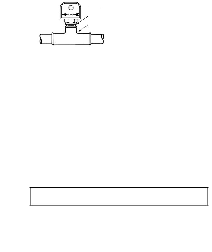
Figure 6, Flow Switch Mounting
Flow direction marked  on switch
I in. (25mm) NPT flow switch connection
Tee
If flow switches, by themselves, are being used, electrical connections in the Unit Control Panel must be made from the common T3-S terminal to terminal CF for the condenser switch and T3-S to terminal EF for the evaporator switch. See Figure 14, Field Wiring Diagram on page 34. The normally open contacts of the flow switch must be wired between the terminals. Flow switch contact quality must be suitable for 24 VAC, low current (16ma). Flow switch wire must be in separate conduit from any high voltage conductors (115 VAC and higher).
Table 1, Flow Switch Flow Rates
Pipe Size |
inch |
1 1/4 |
1 1/2 |
2 |
2 1/2 |
3 |
4 |
5 |
6 |
8 |
||
(NOTE !) |
mm |
32 (2) |
38 (2) |
51 |
63 (3) |
76 |
102 (4) |
127 (4) |
153 (4) |
204 (5) |
||
|
Flow |
gpm |
5.8 |
7.5 |
13.7 |
18.0 |
27.5 |
65.0 |
125.0 |
190.0 |
205.0 |
|
Min. |
Lpm |
1.3 |
1.7 |
3.1 |
4.1 |
6.2 |
14.8 |
28.4 |
43.2 |
46.6 |
||
|
||||||||||||
Adjst. |
No |
gpm |
3.7 |
5.0 |
9.5 |
12.5 |
19.0 |
50.0 |
101.0 |
158.0 |
170.0 |
|
|
Flow |
Lpm |
0.8 |
1.1 |
2.2 |
2.8 |
4.3 |
11.4 |
22.9 |
35.9 |
38.6 |
|
|
Flow |
gpm |
13.3 |
19.2 |
29.0 |
34.5 |
53.0 |
128.0 |
245.0 |
375.0 |
415.0 |
|
Max. |
Lpm |
3.0 |
4.4 |
6.6 |
7.8 |
12.0 |
29.1 |
55.6 |
85.2 |
94.3 |
||
|
||||||||||||
Adjst. |
No |
gpm |
12.5 |
18.0 |
27.0 |
32.0 |
50.0 |
122.0 |
235.0 |
360.0 |
400.0 |
|
|
Flow |
Lpm |
2.8 |
4.1 |
6.1 |
7.3 |
11.4 |
27.7 |
53.4 |
81.8 |
90.8 |
|
NOTES:
1.A segmented 3-inch paddle (1, 2, and 3 inches) is furnished mounted, plus a 6-inch paddle loose.
2.Flow rates for a 2-inch paddle trimmed to fit the pipe.
3.Flow rates for a 3-inch paddle trimmed to fit the pipe.
4.Flow rates for a 3-inch paddle.
5.Flow rates for a 6-inch paddle
6.There is no data for pipe sizes above 8-inch. A switch minimum setting should provide protection against no flow and close well before design flow is reached.
Alternatively, for a higher margin of protection, normally open auxiliary contacts in the pump starters can be wired in series with the flow switches as shown in Figure 14, Field Wiring Diagram on page 34.
 CAUTION
Freeze Notice: Neither the evaporator nor the condenser is self-draining; both must be blown out to help avoid damage from freezing.
The piping should also include thermometers at the inlet and outlet connections and air vents at the high points.
The water heads can be interchanged (end for end) so that the water connections can be made at either end of the unit. If this is done, new head gaskets must be used and control sensors relocated.
In cases where the water pump noise can be objectionable, vibration isolation sections are recommended at both the inlet and outlet of the pump. In most cases, it will not be necessary to provide vibration eliminator sections in the condenser inlet and outlet water lines. But they can be required where noise and vibration are critical.
D–EIMWC00808-16HU - 18/64

Cooling Towers
The condenser water flow rate must be checked to be sure that it conforms to the system design. Some form of temperature control is also required if an uncontrolled tower can supply water below about 65 F (18 C). If tower fan control is not adequate, a tower bypass valve is recommended. Unless the system and chiller unit are specifically for condenser bypass or variable condenser flow is not recommended since low condenser flow rates can cause unstable operation and excessive tube fouling.
The condenser water pumps must cycle on and off with the unit. See Figure 14, Field Wiring Diagram on page 34 for wiring details.
Tower water treatment is essential for continued efficient and reliable unit operation. If not available in-house, competent water treatment specialists can be contracted.
D–EIMWC00808-16HU - 19/64

Field Insulation Guide
Figure 7, Insulation Requirements, Cooling-only Units
D–EIMWC00808-16HU - 20/64

D–EIMWC00808-16HU - 21/64
Physical Data and Weights
Evaporator
The standard insulation of cold surfaces includes the evaporator and non-connection water head, suction piping, compressor inlet, motor housing, and motor coolant outlet line.
Insulation is UL recognized (File # E55475). It is 3/4" thick ABS/PVC flexible foam with a skin. The K factor is 0.28 at 75°F. Sheet insulation is fitted and cemented in place forming a vapor barrier, then painted with a resilient epoxy finish that resists cracking.
The insulation complies to, or has been tested in accordance, with the following:
ASTM-C-177 |
ASTM-C-534 Type 2 |
UL 94-5V |
ASTM-D-1056-91-2C1 |
ASTM E 84 |
MEA 186-86-M Vol. N |
CAN/ULC S102-M88 |
|
|
Refrigerant-side design pressure is 200 psi (1380 kPa) on DWSC units and 180 psi (1242 kPa) on DWDC units. Waterside is 150 psi (1034 kPa) on all.
In the event insulation is to be field-installed, none of the cold surfaces identified above will be factory insulated. Required field insulation is shown beginning on page 20. Approximate total square footage of insulation surface required for individual packaged chillers is tabulated by evaporator code and can be found below.
Table 2, Evaporator Physical Data
|
|
|
Refrigerant |
Evaporator |
Insulation |
|
|
||||
Evaporator |
|
|
Water |
Vessel Weight |
Number of |
||||||
DWSC |
DWDC |
Charge |
Area |
||||||||
Code |
Capacity, gal |
lb. (kg) |
Relief Valves |
||||||||
|
|
lb. (kg) |
Sq. Ft. (m2) |
||||||||
|
|
|
|
|
|
(L) |
|
|
|
|
|
E2209 |
X |
|
729 |
(331) |
54 |
(206) |
66 |
(6.1) |
3285 (1488) |
2 |
|
E2212 |
X |
|
500 |
(227) |
45 |
(170) |
90 |
(8.3) |
2877 (1305) |
2 |
|
E2212 |
|
X |
645 |
(291) |
63 |
(240) |
90 |
(8.3) |
3550 (1609) |
2 |
|
E2216 |
|
X |
1312 (595) |
79 |
(301) |
144 |
(13.4) |
4200 (1903) |
4 |
||
E2412 |
|
X |
1005 (456) |
88 |
(335) |
131 |
(12.1) |
4410 (1999) |
2 |
||
E2416 |
|
X |
1424 (646) |
110 (415) |
157 |
(14.6) |
5170 (2343) |
4 |
|||
E2609 |
X |
|
531 |
(249) |
54 |
(295) |
76 |
(7.1) |
2730 (1238) |
2 |
|
E2612 |
X |
|
708 |
(321) |
72 |
(273) |
102 (9.4) |
3640 (1651) |
2 |
||
E2612 |
|
X |
925 |
(418) |
101 (381) |
102 (9.4) |
4745 (2150) |
2 |
|||
E2616 |
|
X |
1542 (700) |
126 (478) |
162 |
(15.0) |
5645 (2558) |
4 |
|||
E3009 |
X |
|
676 |
(307) |
67 |
(252) |
86 |
(8.0) |
3582 (1625) |
2 |
|
E3012 |
X |
|
901 |
(409) |
89 |
(336) |
115 |
(10.6) |
4776 (2166) |
2 |
|
E3016 |
|
X |
2117 (960) |
157 (594) |
207 |
(19.2) |
7085 (3211) |
4 |
|||
E3609 |
X |
|
988 |
(720) |
118 (445) |
155 14.4) |
5314 (2408) |
2 |
|||
E3612 |
X |
|
1317 (597) |
152 (574) |
129 |
(11.9) |
6427 (2915) |
4 |
|||
E3616 |
|
X |
3320 |
(1506) |
243 (918) |
239 |
(22.2) |
9600 (4351) |
4 |
||
E3620 |
|
|
4150 |
(1884) |
434 |
(1643) |
330 |
(30.6) |
12500 (5675) |
2 |
|
E4212 |
X |
|
1757 (797) |
222 (841) |
148 |
(13.7) |
8679 (3937) |
4 |
|||
E4216 |
|
X |
4422 |
(2006) |
347 |
(1313) |
264 |
(24.5) |
12215 (5536) |
4 |
|
E4220 |
|
X |
4713 |
(2138) |
481 |
(1819) |
330 |
(30.6) |
15045 (6819) |
6 |
|
E4812 |
X |
|
2278 |
(1033) |
327 |
(1237) |
169 |
(15.6) |
10943 (4964) |
4 |
|
E4816 |
|
X |
4690 |
(2128) |
556 |
(2106) |
302 |
(28.1) |
16377 (7429) |
6 |
|
E4820 |
|
X |
5886 |
(2670) |
661 |
(2503) |
377 |
(35.0) |
17190 (7791) |
6 |
|
1.Refrigerant charge is approximate since the actual charge will depend on other variables. Actual charge will be shown on the unit nameplate.
2.Water capacity is based on standard tube configuration and standard dished heads.
3.The evaporator charge includes the maximum condenser charge available with that evaporator and is therefore the maximum charge for a total unit with the evaporator. Actual charge for a specific selection can vary with tube count and can be obtained from the Daikin Selection Program. The program will not allow a selection where the unit charge exceeds the condenser pumpdown capacity.
Condenser
With positive pressure systems, the pressure variance with temperature is always predictable, and the vessel design and relief protection are based upon pure refrigerant characteristics. R-134a requires ASME vessel design, inspection and testing and uses spring-loaded pressure relief valves. When an over pressure condition occurs, spring-loaded relief valves purge only that refrigerant required to reduce system pressure to their set pressure, and then close.
D–EIMWC00808-16HU - 22/64
 Loading...