Daikin CTXG09QVJUW, CTXG12QVJUW, CTXG18QVJUW, CTXG09QVJUS, CTXG12QVJUS Installation Manual
...
DAIKIN ROOM AIR CONDITIONER
INSTALLATION MANUAL
R410A Split Series
Installation manual
Manuel d’installation
Manual de instalación
Español Français English
MODELS
CTXG09QVJUW
CTXG12QVJUW
CTXG18QVJUW
CTXG09QVJUS
CTXG12QVJUS
CTXG18QVJUS

Contents |
|
|
Safety Considerations ..................................... |
1 |
|
Accessories ...................................................... |
3 |
|
Choosing an Installation Site .......................... |
3 |
|
1. |
Indoor unit.................................................................... |
3 |
2. |
Wireless remote controller ........................................... |
3 |
Indoor Unit Installation Diagram ..................... |
4 |
|
Indoor Unit Installation .................................... |
5 |
|
1. |
Installing the mounting plate ........................................ |
5 |
2. |
Drilling a wall hole and installing wall embedded pipe ... |
5 |
3. |
Installing the indoor unit ............................................... |
5 |
4. |
Wiring........................................................................... |
8 |
5. |
Drain piping.................................................................. |
9 |
Refrigerant Piping Work .................................. |
9 |
|
1. |
Flaring the pipe end ..................................................... |
9 |
2. |
Refrigerant piping....................................................... |
10 |
Installation Tips .............................................. |
11 |
|
1. |
Removing and installing the upper front panel........... |
11 |
2. |
Removing and installing the front grille...................... |
11 |
3. |
How to set the different addresses ............................ |
12 |
4. |
When connecting a wireless LAN connecting adapter..... |
12 |
5. |
When connecting to an HA system............................ |
13 |
Trial Operation and Testing .......................... |
14 |
|
1. |
Trial operation and testing ......................................... |
14 |
2. |
Test items .................................................................. |
14 |
Safety Considerations
Read these Safety Considerations for Installation carefully before installing an air conditioner or heat pump. After completing the installation, make sure that the unit operates properly during the startup operation.
Instruct the user on how to operate and maintain the unit. Inform users that they should store this installation manual with the operation manual for future reference.
Always use a licensed installer or contractor to install this product. Improper installation can result in water or refrigerant leakage, electric shock, fire, or explosion.
Meanings of DANGER, WARNING, CAUTION, and NOTE
Symbols:
DANGER ···············Indicates an imminently hazardous
situation which, if not avoided, will result in death or serious injury.
WARNING ·············Indicates a potentially hazardous
situation which, if not avoided, could result in death or serious injury.
CAUTION ··············Indicates a potentially hazardous
situation which, if not avoided, may result in minor or moderate injury. It may also be used to alert against unsafe practices.
NOTE ·····················Indicates situations that may result in
equipment or property-damage accidents only.
 DANGER
•Refrigerant gas is heavier than air and replaces oxygen. A massive leak can lead to oxygen depletion, especially in
basements, and an asphyxiation hazard could occur leading to serious injury or death.
•Do not ground units to water pipes, gas pipes, telephone wires, or lightning rods as incomplete grounding can cause a severe shock hazard resulting in severe injury or death. Additionally, grounding to gas pipes could cause a gas leak and potential explosion causing severe injury or death.
•If refrigerant gas leaks during installation, ventilate the area immediately. Refrigerant gas may produce toxic gas if it comes into contact with fire. Exposure to this gas could cause severe injury or death.
•After completing the installation work, check that the refrigerant gas does not leak throughout the system.
•Do not install unit in an area where flammable materials are present due to risk of explosions that can cause serious injury or death.
•Safely dispose all packing and transportation materials in accordance with federal/state/local laws or ordinances. Packing materials such as nails and other metal or wood parts, including plastic packing materials used for transportation may cause injuries or death by suffocation.
 WARNING
•Only qualified personnel must carry out the installation work. Installation must be done in accordance with this installation manual. Improper installation may result in water leakage, electric shock, or fire.
•When installing the unit in a small room, take measures to keep the refrigerant concentration from exceeding allowable safety limits. Excessive refrigerant leaks, in the event of an accident in a closed ambient space, can lead to oxygen deficiency.
•Use only specified accessories and parts for installation work. Failure to use specified parts may result in water leakage, electric shock, fire, or the unit falling.
•Install the air conditioner or heat pump on a foundation strong enough that it can withstand the weight of the unit. A foundation of insufficient strength may result in the unit falling and causing injuries.
•Take into account strong winds, typhoons, or earthquakes when installing. Improper installation may result in the unit falling and causing accidents.
1 |
English■ |

•Make sure that a separate power supply circuit is provided for this unit and that all electrical work is carried out by qualified personnel according to local, state, and national regulations. An insufficient power supply capacity or improper electrical construction may lead to electric shock or fire.
•Make sure that all wiring is secured, that specified wires are used, and that no external forces act on the terminal connections or wires. Improper connections or installation may result in fire.
•When wiring, position the wires so that the electrical wiring box cover can be securely fastened. Improper positioning of the electrical wiring box cover may result in electric shock, fire, or the terminals overheating.
•Before touching electrical parts, turn off the unit.
•It is recommended to install a ground fault circuit interrupter if one is not already available. This helps prevent electric shock or fire.
•Securely fasten the outdoor unit terminal cover (panel). If the terminal cover/panel is not installed properly, dust or water may enter the outdoor unit causing fire or electric shock.
•When installing or relocating the system, keep the refrigerant circuit free from substances other than the specified refrigerant (R410A) such as air. Any presence of air or other foreign substance in the refrigerant circuit can cause an abnormal pressure rise or rupture, resulting in injury.
•Do not change the setting of the protection devices. If the pressure switch, thermal switch, or other protection device is shorted and operated forcibly, or parts other than those specified by Daikin are used, fire or explosion may occur.
 CAUTION
•Do not touch the switch with wet fingers. Touching a switch with wet fingers can cause electric shock.
•Do not allow children to play on or around the unit to prevent injury.
•The heat exchanger fins are sharp enough to cut. To avoid injury wear gloves or cover the fins while working around them.
•Do not touch the refrigerant pipes during and immediately after operation as the refrigerant pipes may be hot or cold, depending on the condition of the refrigerant flowing through the refrigerant piping, compressor, and other refrigerant cycle parts. Your hands may suffer burns or frostbite if you touch the refrigerant pipes. To avoid injury, give the pipes time to return to normal temperature or, if you must touch them, be sure to wear proper gloves.
•Install drain piping to proper drainage. Improper drain piping may result in water leakage and property damage.
•Insulate piping to prevent condensation.
•Be careful when transporting the product.
•Do not turn off the power immediately after stopping operation. Always wait for at least 5 minutes before turning off the power. Otherwise, water leakage may occur.
•Do not use a charging cylinder. Using a charging cylinder may cause the refrigerant to deteriorate.
•Refrigerant R410A in the system must be kept clean, dry, and tight.
(a)Clean and Dry -- Foreign materials (including mineral oils such as SUNISO oil or moisture) should be prevented from getting into the system.
(b)Tight -- R410A does not contain any chlorine, does not destroy the ozone layer, and does not reduce the earth’s protection again harmful ultraviolet radiation. R410A can contribute to the greenhouse effect if it is released. Therefore take proper measures to check for the tightness of the refrigerant piping installation. Read the chapter Refrigerant Piping Work and follow the procedures.
•Since R410A is a blend, the required additional refrigerant must be charged in its liquid state. If the refrigerant is charged in a state of gas, its composition can change and the system will not work properly.
•The indoor unit is for R410A. See the catalog for indoor models that can be connected. Normal operation is not possible when connected to other units.
•Remote controller (wireless kit) transmitting distance can be shorter than expected in rooms with electronic fluorescent lamps (inverter or rapid start types). Install the indoor unit far away from fluorescent lamps as much as possible.
•Indoor units are for indoor installation only. Outdoor units can be installed either outdoors or indoors. This unit is for indoor use.
•Do not install the air conditioner or heat pump in the following locations:
(a)Where a mineral oil mist or oil spray or vapor is produced, for example, in a kitchen.
Plastic parts may deteriorate and fall off or result in water leakage.
(b)Where corrosive gas, such as sulfurous acid gas, is produced.
Corroding copper pipes or soldered parts may result in refrigerant leakage.
(c)Near machinery emitting electromagnetic waves. Electromagnetic waves may disturb the operation of the control system and cause the unit to malfunction.
(d)Where flammable gas may leak, where there is carbon fiber, or ignitable dust suspension in the air, or where volatile flammables such as thinner or gasoline are handled. Operating the unit in such conditions can cause a fire.
•Take adequate measures to prevent the outdoor unit from being used as a shelter by small animals. Small animals making contact with electrical parts can cause malfunctions, smoke, or fire. Instruct the user to keep the area around the unit clean.
 NOTE
NOTE
•The indoor unit should be positioned where the unit and interunit wires (outdoor to indoor) are at least 3.3ft (1m) away from any televisions or radios. (The unit may cause interference with the picture or sound.) Depending on the radio waves, a distance of 3.3ft (1m) may not be sufficient to eliminate the noise.
•Dismantling the unit, treatment of the refrigerant, oil and additional parts must be done in accordance with the relevant local, state, and national regulations.
•Do not use the following tools that are used with conventional refrigerants: gauge manifold, charge hose, gas leak detector, reverse flow check valve, refrigerant charge base, vacuum gauge, or refrigerant recovery equipment.
•If the conventional refrigerant and refrigerator oil are mixed in R410A, the refrigerant may deteriorate.
•This air conditioner or heat pump is an appliance that should not be accessible to the general public.
•As design pressure is 604 psi, the wall thickness of fieldinstalled pipes should be selected in accordance with the relevant local, state, and national regulations.
FTN001-U
English■ |
2 |
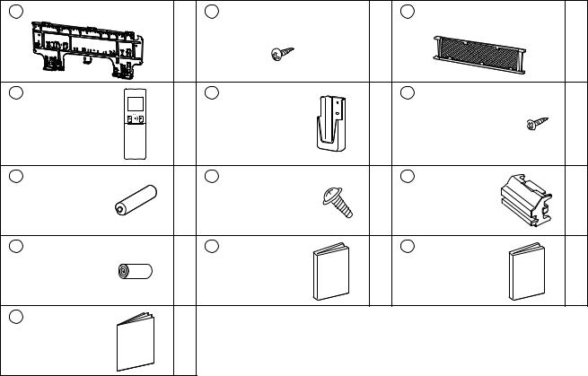
Accessories
A Mounting plate |
|
B Mounting plate fixing screw |
|
C Titanium apatite photocatalytic |
|
|
|
|
M4 × 1” (M4 × 25mm) |
|
|
air-purifying filter |
|
|
1 |
|
5 |
|
|
2 |
D Wireless remote |
|
E Remote |
|
F |
Remote |
|
controller |
|
controller holder |
|
|
controller holder |
|
|
1 |
|
1 |
|
fixing screw |
2 |
|
|
|
M3 × 13/16” |
|||
|
|
|
|
|
|
|
|
|
|
|
|
(M3 × 20mm) |
|
G Dry battery |
|
H Indoor unit |
|
J |
Screw cover |
|
AAA. LR03 |
2 |
fixing screw |
2 |
|
|
2 |
(alkaline) |
M4 × 1/2” |
|
|
|||
|
|
(M4 × 12mm) |
|
|
|
|
K Insulation tape |
|
L Operation |
|
M Installation |
|
|
|
1 |
manual |
1 |
|
manual |
1 |
|
|
|
|
|||
N Warranty
1
Choosing an Installation Site
Before choosing the installation site, obtain user approval.
1. Indoor unit
The indoor unit should be positioned in a place where:
1)the restrictions on the installation requirements specified in “Indoor Unit Installation Diagram” on page 4 are met,
2)both the air inlet and air outlet are unobstructed,
3)the unit is not exposed to direct sunlight,
4)the unit is away from sources of heat or steam,
5)there is no source of machine oil vapor (this may shorten the indoor unit service life),
6)cool/warm air is circulated throughout the room,
7)the unit is away from electronic ignition type fluorescent lamps (inverter or rapid start type) as they may affect the remote controller range,
8)no laundry equipment is nearby.
2.Wireless remote controller
Turn on all the fluorescent lamps in the room, if any, and find a location where the remote controller signals are properly received by the indoor unit (within 19-11/16ft (6m)).
3 |
English■ |
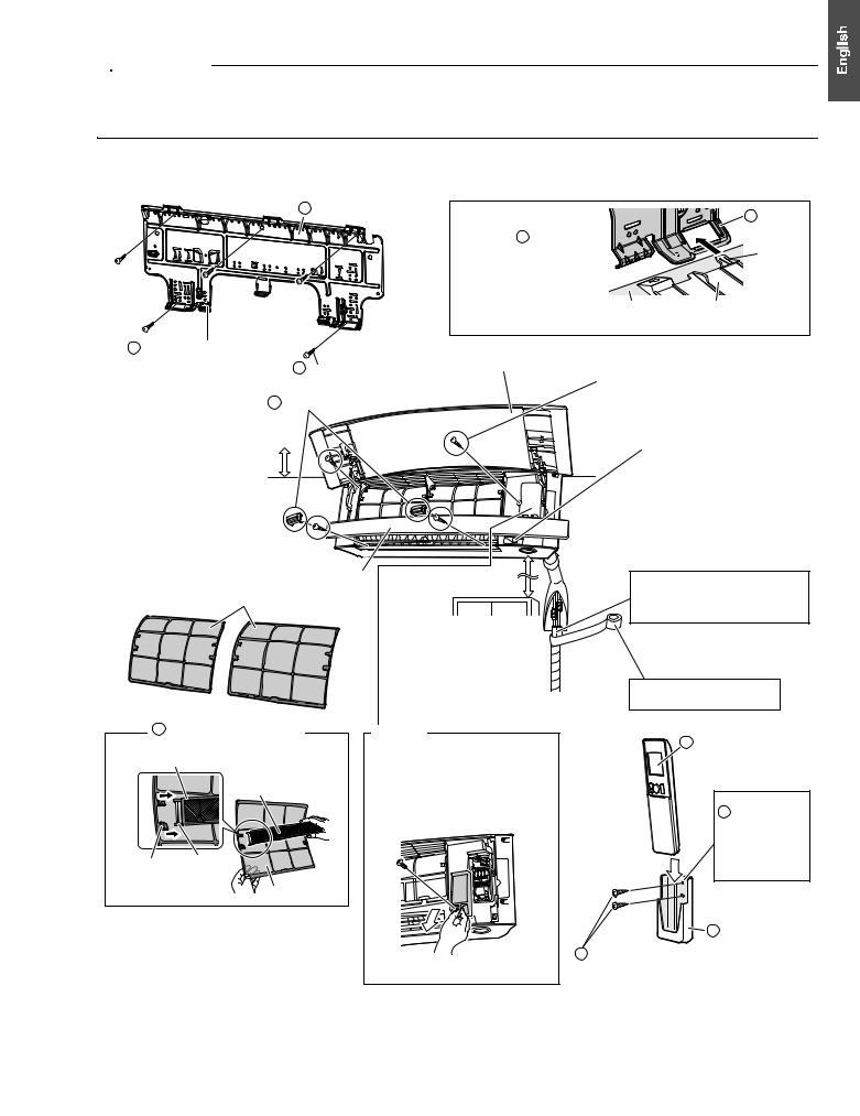
Indoor Unit Installation Diagram
 CAUTION
•Do not hit or violently push the INTELLIGENT EYE sensor. This can lead to damage and malfunction.
•Do not place large objects near the INTELLIGENT EYE sensor. Also keep heating units or humidifiers outside the sensor’s detection area.
A Mounting plate |
How to attach the indoor unit |
|
|
|
Hook the hooks of the bottom |
|
frame to the A mounting plate. |
|
If the hooks are difÞcult to hook, |
|
remove the front grille. |
How to remove the indoor unit
Push up the lower part of the front grille to release the hooks. If it is difÞcult to release, remove the front grille.
A Mounting
plate


 Hook
Hook
Front grille |
Bottom frame |
The A mounting plate should |
|
|
be installed on a wall which |
B Mounting plate Þxing |
Upper front panel |
can support the weight of the |
||
indoor unit. |
screws M4 × 1Ó (M4 × 25mm) |
|
|
|
|
J Screw covers
1-3/16Ó (30mm) or more from ceiling
1-15/16Ó (50mm) or more from walls (on both sides) 
Lower front panel
19-11/16Ó (500mm) or more
Air Þlters
Make sure that there are no obstacles within 19-11/16 inch (500mm) under the signal receiver.
Such obstacles, if any, may have an adverse inßuence on the reception performance of the receiver and the reception distance may be shortened.
Screws M4 × 5/8Ó (M4 × 16mm)
When dismounting the front grille, refer
to “2. Removing and installing the front grille” on page 11.
INTELLIGENT EYE sensor
Cut thermal insulation pipe to an appropriate length and wrap it with tape, making sure that no gap is left in the insulation pipeÕs cut line.
Wrap the insulation pipe with the Þnishing tape from bottom to top.
C Titanium apatite photocatalytic |
Service lid |
|||
|
air-purifying Þlter (2) |
|||
|
The service lid is removable. |
|||
|
|
|
||
Filter frame |
Titanium apatite |
Opening method |
||
|
|
photocatalytic |
1) |
Remove the service lid screws. |
|
|
2) |
Pull out the service lid diagonally |
|
|
|
air-purifying Þlter |
||
|
|
|
down in the direction of the arrow. |
|
|
|
|
|
|
|
|
|
3) |
Pull down. |
Claw |
Tab |
|
|
|
|
|
|
|
|
|
|
Air Þlter |
|
|
D Wireless remote controller
Before screwing the E remote controller holder to the wall, make sure that control signals are properly received by indoor unit.
E Remote controller holder
FRemote controller holder Þxing screws
M3 × 13/16Ó (M3 × 20mm)
English■ |
4 |
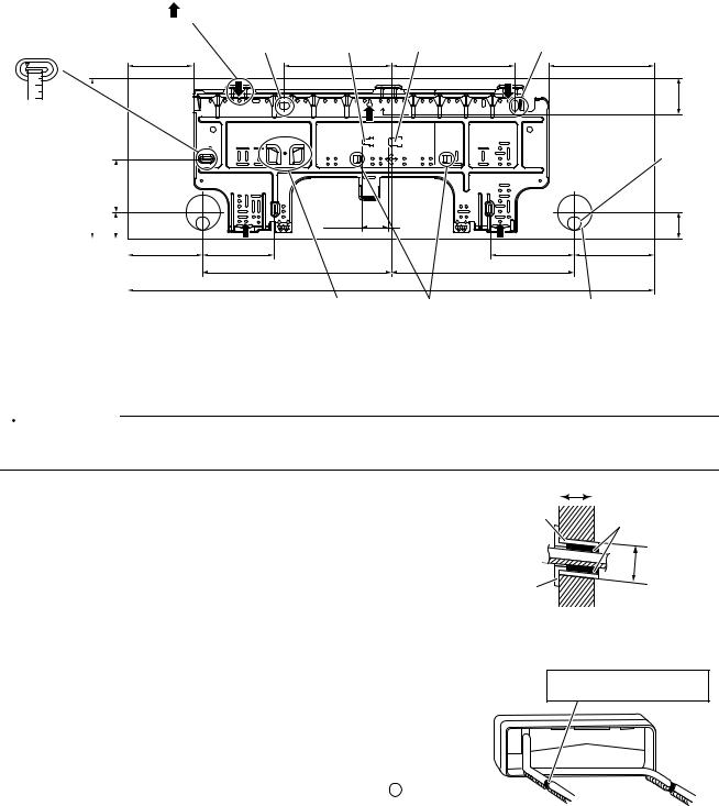
Indoor Unit Installation
1. Installing the mounting plate
The mounting plate should be installed on a wall which can support the weight of the indoor unit.
1)Temporarily secure the mounting plate to the wall, make sure that the plate is completely level, and mark the drilling points on the wall.
2)Secure the mounting plate to the wall with screws.
Recommended mounting plate retention spots and dimensions
Recommended mounting plate retention spots (5 spots in all)
(Bolt size: 3/8 (M10)) Liquid pipe end |
Gas pipe end |
(Bolt size: 3/8 (M10)) |
Use a tape measure as shown.
Position the end of the tape measure at  .
.
11-15/16 (303) |
|
3-15/16 |
(100) |
|
|
|
|||||
|
|
1-15/16 |
(49) |
|
|
|
|
|
|||
|
|||||
|
|
||||
|
|
|
|
|
|
4-7/8 (124) |
8 (203) |
9-3/16 (234) |
7-7/8 (200) |
|
|
|
|
2-5/8 |
(67) |
|
|
|
Drain hose |
|
|
|
|
position |
|
|
1-15/16 |
|
15/16-1 |
(49) |
|
(50) |
|
||
|
|
|
|
|
5-9/16 (142) |
5-5/16 (135) |
6-5/16 (160) |
5-15/16 (151) |
|
|
14-1/16 (357) |
13-11/16 (348) |
|
|
|
|
39-5/16 (998) |
|
|
Place the pipe port |
Place a leveler |
Through-the-wall hole |
cover in this pocket. |
on these tabs. |
φ2-9/16 (65) |
|
|
unit: inch (mm) |
2. Drilling a wall hole and installing wall embedded pipe
 WARNING
For metal frame or metal board walls, be sure to use a wall embedded pipe and wall hole cover in the feed-through hole to prevent possible heat, electric shock, or fire.
• Be sure to caulk the gaps around the pipes with caulking material to |
Inside |
Outside |
prevent condensation. |
1)Drill a feed-through hole with a 2-9/16 inch (65mm) diameter through the wall at a downward angle toward the outside.
2)Insert a wall embedded pipe into the hole.
3)Insert a wall hole cover into wall pipe.
4)After completing refrigerant piping, wiring, and drain piping, caulk the pipe hole gap with putty.
3.Installing the indoor unit
Wall embedded pipe |
Caulking |
|
(Þeld supply) |
||
(Þeld supply) |
||
|
||
|
φ2-9/16Ó |
|
|
(65mm) |
|
Wall hole cover |
|
|
(Þeld supply) |
|
•The recommended installation method is back piping.
•When performing bottom piping or left side piping, refer to “3-4. Bottom or left side piping” on page 7.
•Right side piping cannot be performed.
3-1. Right-back piping
1)Attach the drain hose to the underside of the refrigerant pipes with adhesive vinyl tape.
2)Wrap the refrigerant pipes and drain hose together with K insulation tape.
Bind refrigerant pipe and drain hose together with adhesive vinyl tape.
Right back piping |
Left back piping |
5 |
English■ |
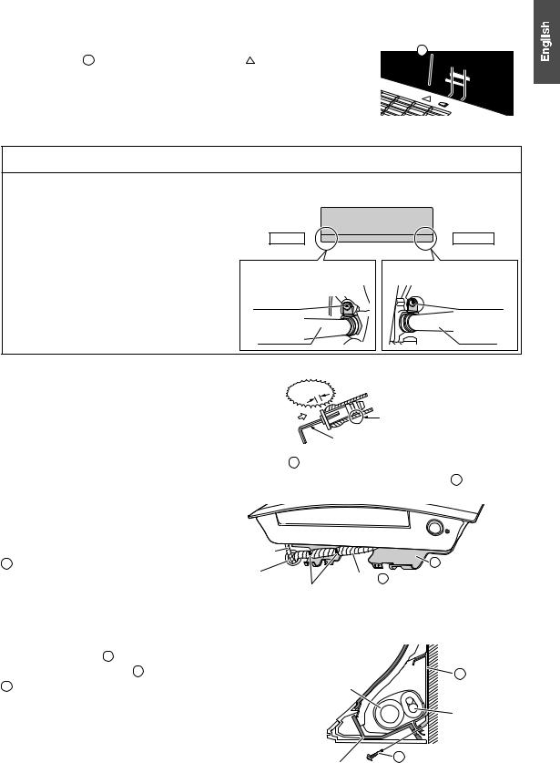
3) Pass the drain hose and refrigerant pipes through the wall hole, then position the |
A Mounting plate |
|
indoor unit on the A mounting plate hooks, using the markings at the top of |
||
|
||
the indoor unit as a guide. |
|
3-2. Left-back piping
1) Replace the drain plug and drain hose.
How to replace the drain plug and drain hose
Replacing onto the left side
1)Remove the Þxing screw on the right side and remove the drain hose.
2)Remove the drain plug on the left side and attach it to the right side.
3)Insert the drain hose and tighten with the included Þxing screw. Forgetting to tighten this may cause water leakages.
Drain hose attachment position
The drain hose is on the back of the unit.
Left side |
Right side |
Front side of unit |
|
Attachment on the left side |
Attachment on the right side |
|
(factory default) |
Fixing screw |
Fixing screw |
Drain hose |
Drain hose |
2)Attach the drain hose to the underside of the refrigerant pipes with adhesive vinyl tape.
3)Be sure to connect the drain plug to the drain port in place of without drain hose.
How to set the drain plug
|
gap |
Do not apply lubricating oil (refrigerant |
|
No |
oil) to the drain plug when inserting it. |
||
|
|||
|
|
||
|
|
The application of lubrication oil to the |
|
|
|
drain plug will deteriorate the plug to |
|
|
|
cause drain leakage from the plug. |
|
|
|
Insert a hexagonal wrench (3/16 inch (4mm)). |
4)Shape the refrigerant pipes along the pipe path marking on the A mounting plate.
5)Pass the drain hose and refrigerant pipes through the wall hole, then position the indoor unit on the A mounting
plate hooks, using the  markings at the top of the indoor unit as a guide. 6) Connect the refrigerant pipes.
7) In case of pulling the drain hose through the |
|
|
|
|
back of the indoor unit, wrap the refrigerant |
|
|
|
|
pipes and drain hose together with |
Drain hose |
|
|
|
K insulation tape as shown in the figure. |
|
|
|
A Mounting plate |
|
Caulk this hole |
|
Wrap |
K insulation tape around the bent |
|
with putty or |
Bind with |
portion of the refrigerant pipe. |
|
|
caulking material. |
adhesive |
Overlap at least half the width of the tape |
|
|
|
vinyl tape. |
with each turn. |
|
8) Press the bottom edge of the indoor unit with both hands until it |
|
|
|
|
is firmly caught by the A mounting plate hooks. |
|
|
|
|
Secure the indoor unit to the A mounting plate with the |
|
|
A Mounting plate |
|
H indoor unit fixing screws M4 × 1/2” (M4 × 12mm). |
Drain hose |
|
||
|
|
|
|
Refrigerant pipes |
|
|
|
|
H Indoor unit Þxing screw |
|
|
Bottom frame |
M4 × 1/2Ó (M4 × 12mm) |
|
|
|
|
|
(2 points) |
English■ |
6 |
Indoor Unit Installation
3-3. Wall embedded piping
Follow the instructions given under left-back piping.
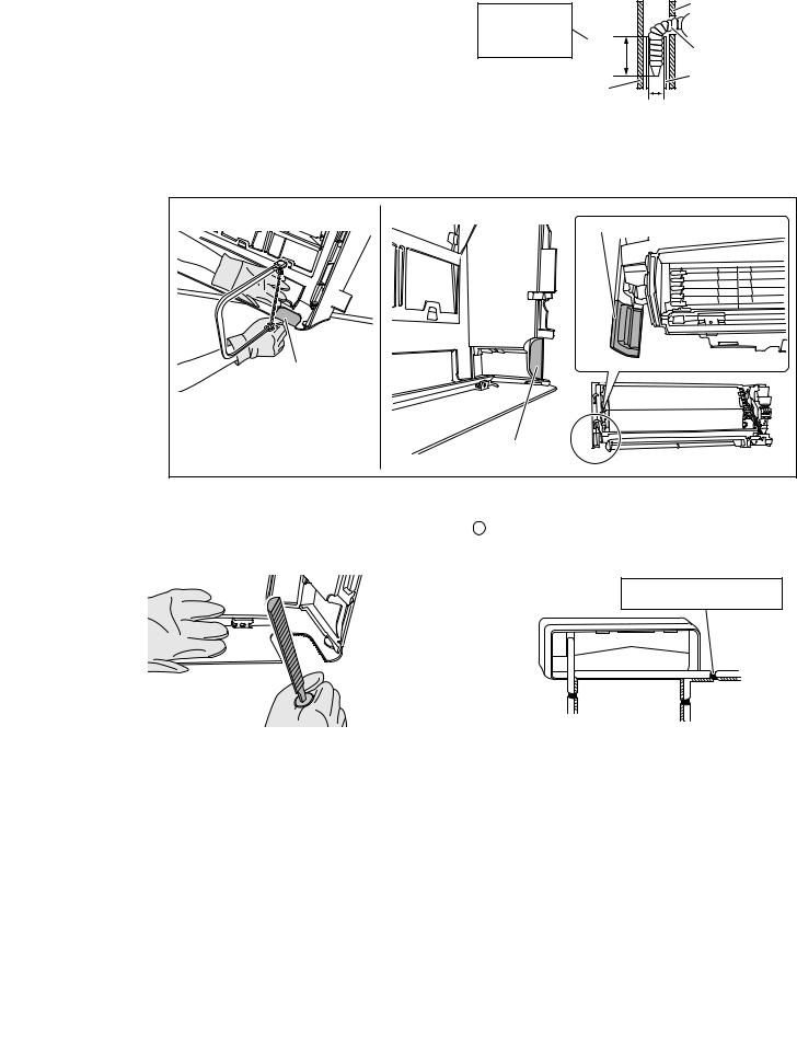
1)Insert the drain hose to this depth so it won’t be pulled out of the drain pipe.
3-4. Bottom or left side piping
Insert the drain |
|
Inner wall |
|
|
|
||
hose to this depth |
|
|
|
so it wonÕt be pulled |
1-15/16Ó |
|
|
out of the drain pipe. |
Drain hose |
||
(50mm) |
|||
|
|||
|
|
||
|
or more |
Vinyl chloride |
|
|
|
||
Outer wall |
drain pipe (VP-30) |
||
|
φ1-3/16Ó (30mm) or more |
||
1)Cut off the pipe port cover with a copping saw.
•For bottom piping: On the bottom of the front grille
•For left side piping: On the side cover (front grille side and unit side)
Apply the blade of the copping saw to the notch, and cut off the pipe port cover along the uneven inner surface.
Side cover (unit side)
Front grille side
The figure shows the case of left-bottom piping.
Side cover (front grille side)
2)After cutting off the pipe port cover, perform filing.
Remove the burrs along the cut section using a half round needle file.
3)Wrap the refrigerant pipes and drain hose together with K insulation tape.
Then, insert the drain hose and refrigerant pipes into the wall hole after inserting them into the cut out piping hole
opened.
Bind refrigerant pipe and drain hose together with adhesive vinyl tape.
|
Left side |
|
piping |
Right bottom piping |
Left bottom piping |
NOTE
•Be careful not to let chips enter the driving section of the arm.
•Be careful not to put pressure on the lower front panel.
7 |
English■ |
4. Wiring
Refer to the installation manual for the outdoor unit also.
 WARNING
•Do not use tapped wires, extension cords, or starburst connections, as they may cause overheating, electric shock, or fire.
•Do not use locally purchased electrical parts inside the product. (Do not branch the power for the drain pump, etc., from the terminal block.) Doing so may cause electric shock or fire.
•Do not connect the power wire to the indoor unit. Doing so may cause electric shock or fire.
 CAUTION
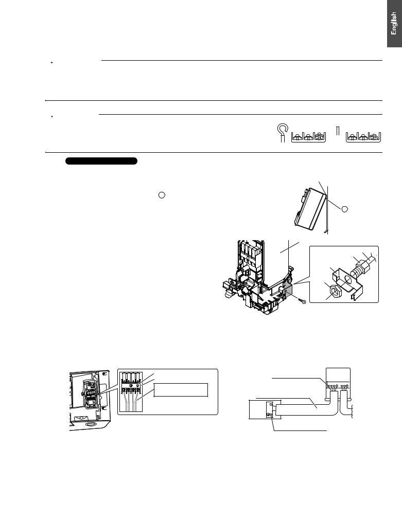
When connecting the connection wire to the terminal block using a single core wire, be sure to perform curling.
Problems with the installation may cause heat and fires.
Good Wrong
With a multi indoor unit , install as described in the installation manual supplied with the multi outdoor
unit.
1)Remove the upper front panel, then remove the service lid. (Refer to the opening method on page 4.)
2)Lift up the unit and place it on the A mounting plate hooks.
3)Remove the front grille.
(Refer to the removal method on page 11.)
4) Remove the conduit mounting plate and then secure the conduit to the conduit mounting plate with the lock nut, as shown in the illustration.
5) Strip wire ends (3/4 inch (20mm)).
6) Match wire colors with terminal numbers on the indoor and outdoor unit’s terminal blocks and firmly secure the wires in the corresponding terminals with the screws.
7) Connect the ground wire to the corresponding terminals. 8) Pull the wires lightly to make sure they are securely
connected.
9)In case of connecting to an adapter system, run the remote controller cable and attach the S21.
(Refer to “5. When connecting to an HA system” on page 13.)
10)Attach the conduit mounting plate.
11)Shape the wires so that the service lid fits securely.
12)Attach the front grille.
13)Attach the service lid and the upper front panel.
Hang indoor unit on the hooks of mounting plate.
A Mounting plate
Electrical wiring box
Conduit pipe
Conduit
Conduit mounting plate
Lock nut
Screw
Terminal block
Electrical wiring box
1 |
2 |
3 |
Shape wires so that the |
|
|
|
|
|
|
|
service lid will Þt securely. |
 Use the speciÞed wire type.
Firmly Þx the wires with the terminal screws.
Outdoor
unit
1 2 3

 L1 L2
L1 L2

Wire size and length must comply with local codes.
1
Indoor 2 unit 3
Firmly Þx the wires with the terminal screws.
English■ |
8 |
Indoor Unit Installation
5. Drain piping
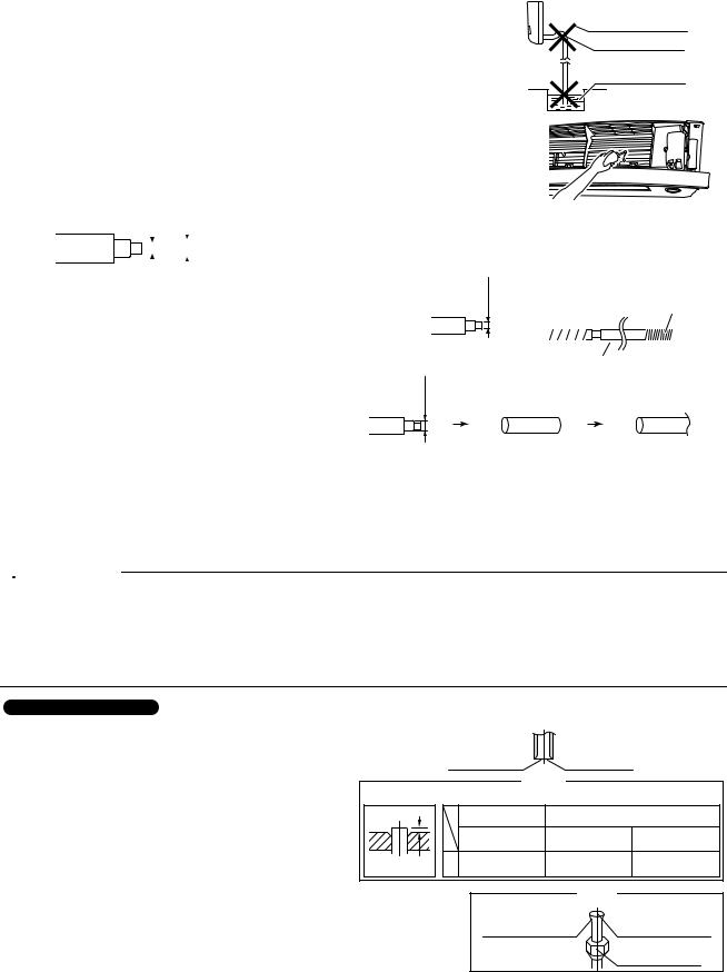
1)Connect the drain hose, as described on the right.
2)Remove the upper front panel and the air filters. (Refer to removal method on page 11.) Pour some water into the drain pan to check the water flows smoothly.
3)If drain hose extension or embedded drain piping is required, use appropriate parts that match the hose front end.
Figure of hose front end
ϕ5/8Ó (ϕ16mm) |
|
ϕ11/16Ó (ϕ18mm) |
|
||||
|
|
|
|
|
|
|
|
|
|
|
|
|
|
|
|
|
|
|
|
|
|
|
|
|
|
|
|
|
|
|
|
|
|
|
|
|
|
|
|
The drain hose should be inclined downward.
No trap is permitted.
Do not put the end of the hose in water.
•When drain hose requires extension, obtain an extension hose with an inner diameter of 5/8 inch (16mm).
Be sure to thermally insulate the indoor section of the extension hose.
ϕ5/8Ó (ϕ16mm)
Drain hose supplied with the indoor unit
Indoor unit |
Extension drain hose |
|||
drain hose |
|
|
|
|
|
|
|
|
|
|
|
|
|
|
Heat insulation tube (Þeld supply)
•When connecting a rigid polyvinyl chloride pipe (nominal diameter 1/2 inch (13mm)) directly to the drain hose attached to the indoor unit as with embedded piping work, use any commercially available drain socket (nominal diameter 1/2 inch (13mm)) as a joint.
ϕ11/16Ó (ϕ18mm)
Drain hose supplied with |
Commercially available |
Commercially available |
the indoor unit |
drain socket |
rigid polyvinyl chloride pipe |
|
(nominal diameter 1/2 inch |
(nominal diameter 1/2 inch |
|
(13mm)) |
(13mm)) |
Refrigerant Piping Work
 WARNING
•Do not apply mineral oil on flared part.
•Prevent mineral oil from getting into the system as this would reduce the service life of the units.
•Never use piping which has been used for previous installations. Only use parts which are delivered with the unit.
•Never install a dryer to this R410A unit in order to guarantee its service life.
•The drying material may dissolve and damage the system.
•Incomplete flaring may result in refrigerant gas leakage.
With a multi indoor unit , install as described in the installation manual supplied with the multi outdoor unit.
1. Flaring the pipe end |
|
Cut exactly at |
|
|
||
1) |
Cut the pipe end with a pipe cutter. |
|
|
|
||
|
right angles. |
Remove burrs. |
|
|||
2) |
Remove burrs with the cut surface facing downward |
|
|
Flaring |
|
|
|
so that the filings do not enter the pipe. |
|
|
|
||
|
Set exactly at the position shown below. |
|
|
|||
3) |
Put the flare nut on the pipe. |
A |
|
Flare tool for |
Conventional ßare tool |
|
4) |
Flare the pipe. |
|
R410A |
|||
|
|
|
||||
|
|
Clutch-type |
Clutch-type |
Wing-nut type |
||
|
|
|
|
|||
5) |
Check that the flaring has been done correctly. |
|
|
(Rigid-type) |
(Imperial-type) |
|
|
|
|
||||
|
|
Die |
A |
0-0.020 inch |
0.039-0.059 inch |
0.059-0.079 inch |
|
|
(0-0.5mm) |
(1.0-1.5mm) |
(1.5-2.0mm) |
||
|
|
|
||||
|
|
|
|
|||
|
Check |
The ßare's inner |
The pipe end must |
surface must be |
be evenly ßared in a |
ßaw-free. |
perfect circle. |
|
Make sure that the |
|
ßare nut is Þtted. |
9 |
English■ |
2. Refrigerant piping
 CAUTION
•Use the flare nut fixed to the main unit. (This is to prevent the flare nut from cracking as a result of deterioration over time.)
•To prevent gas leakage, apply refrigeration oil only to the inner surface of the flare. (Use refrigeration oil for R410A.)
•Use a torque wrench when tightening the flare nuts to prevent damage to the flare nuts and gas leakage.
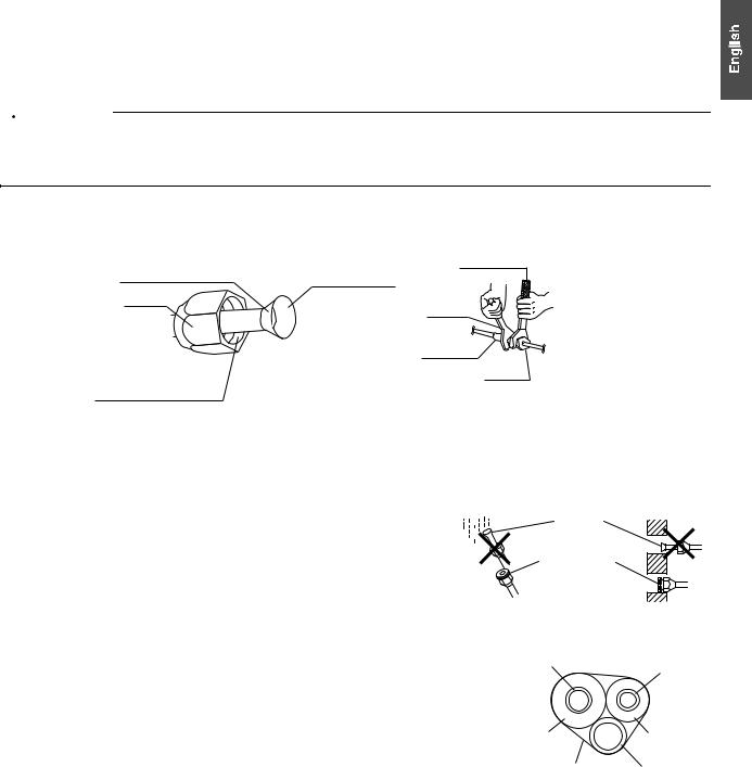
•Align the centers of both flares and tighten the flare nuts 3 or 4 turns by hand, then tighten them fully with a spanner and a torque wrench.
Do not apply refrigeration oil to the outer surface.
Flare nut
Do not apply refrigeration oil to the ßare nut to avoid tightening with excessive torque.
Apply oil
Apply refrigeration oil only to the inner surface of the ßare.
Tighten
Torque wrench
Spanner
Piping union
Flare nut
|
Piping size |
Flare nut tightening torque |
|
|
|
|
|
Gas side |
O.D. 3/8 inch (9.5mm) |
24-1/8–29-1/2ft • Ibf (32.7-39.9N • m) |
|
|
|
||
O.D. 1/2 inch (12.7mm) |
36-1/2–44-1/2ft • lbf (49.5-60.3N • m) |
||
|
|||
|
|
|
|
Liquid side |
O.D. 1/4 inch (6.4mm) |
10-1/2–12-3/4ft • lbf (14.2-17.2N • m) |
|
|
|
|
2-1. Caution on piping handling
• Protect the open end of the pipe against dust and moisture. |
|
|
|
|
|
|
|
||
|
|
|
||
• All pipe bends should be as gentle as possible. Use a pipe bender for |
|
|
|
|
|
|
|
||
Rain |
||||
bending. |
||||
|
|
|
||
Be sure to |
Wall |
place a cap. |
|
If no ßare cap is available, cover the ßare mouth with tape to keep dirt and water out.
2-2. Selection of copper and heat insulation materials
When using commercial copper pipes and fittings, observe the following:
•Insulation material: Polyethylene foam
Heat transfer rate: 0.041 to 0.052W/mK (0.024 to 0.030Btu/fth°F (0.035 to 0.045kcal/mh°C))
Be sure to use insulation that is designed for use with HVAC Systems.
•ACR Copper only.
Gas pipe
Liquid pipe
Gas pipe |
Liquid pipe |
|
insulation |
||
insulation |
||
|
||
Finishing tape |
Drain hose |
• Be sure to insulate both the gas and liquid piping and observe the insulation dimensions as below.
|
Piping size |
Minimum bend radius |
Piping thickness |
Thermal insulation size |
Thermal insulation |
|
|
thickness |
|||||
|
|
|
|
|
||
|
|
|
|
|
|
|
|
O.D. 3/8 inch |
1-3/16 inch (30mm) |
|
I.D. 15/32-19/32 inch |
|
|
Gas side |
(9.5mm) |
or more |
|
(12-15mm) |
|
|
|
|
0.031 inch (0.8mm) |
|
|
||
O.D. 1/2 inch |
1-9/16 inch (40mm) |
I.D. 9/16-5/8 inch |
13/32 inch |
|||
|
||||||
|
(12.7mm) |
or more |
(C1220T-O) |
(14-16mm) |
(10mm) Min. |
|
|
|
|
|
|
|
|
Liquid side |
O.D. 1/4 inch |
1-3/16 inch (30mm) |
|
I.D. 5/16-13/32 inch |
|
|
(6.4mm) |
or more |
|
(8-10mm) |
|
||
|
|
|
||||
|
|
|
|
|
|
• Use separate thermal insulation pipes for gas and liquid refrigerant pipes.
English■ |
10 |
Installation Tips
1. Removing and installing the upper front panel
•Removal method
1)Open the upper front panel.
2)Slide the front panel locks on the back of the front panel upward to release the locks (left and right sides).
3)Remove the panel shafts on both sides from the shaft holes, and dismount the upper front panel.
Back of the upper front panel
Front panel shaft
 3-2) Pull
Back of the upper front panel
Shaft hole |
|
3-1) Slide |
|
|
|
|
2) Slide |
||
|
|
|
|
|
|
|
|
|
|
Front panel lock
• Installation method
1) Slide the front panel locks on the back of the front panel upward to release the locks (left and right sides).
2) Insert the panel shafts on both sides of the upper front panel into the shaft holes. 3) Slide the front panel locks on each side downward to lock them.
4) Close the upper front panel slowly. (See Fig. 1) 5) Do not push on the panel to close it. (See Fig. 2)
6) Turn on the unit using the remote controller. Wait till the upper and lower front panels are completely open. Then, turn off the unit using the remote controller again. (See Fig. 3)
7) Once the both panels close completely, gently push the upper front panel to hook it into position. (See Fig. 4)
2. Removing and installing the front grille
The upper front panel does not open any more than as shown in the figure. Do not force it open any further than that.
Fig. 1


Fig. 2
Fig. 3
ON/OFF
Fig. 4
“click” |
“click” |
 CAUTION
Be sure to wear protection gloves.
•Removal method
1)Remove the upper front panel and air filters.
2)Remove the service lid. (Refer to the opening method on page 4.)
3)Disconnect the wire harnesses from the wire clamp, and remove the wire harnesses from the connectors.
4)Push the lower front panel up until it stops.
5)Dismount the flap (large).
6)Open the 2 screw covers, and remove 4 screws from the front grille. (The screw covers are not factory-mounted.)
Wire clamp
Connectors 

Wire harnesses 
JScrew covers
•Opening method
Downward 

4 screws
Use a long ßat plate such as a ruler and wrap it in a cloth so as not to damage the product.
pushing to the right while bending it slightly
11 |
English■ |
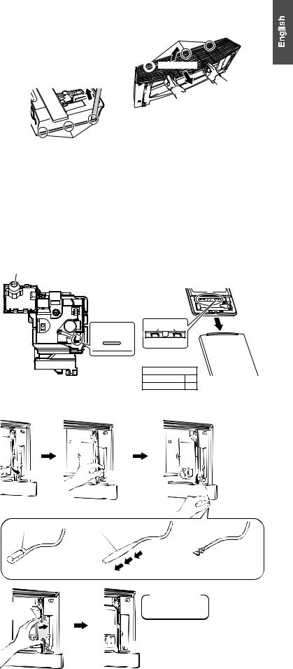
7)Wear protection gloves and insert both hands under the front grille as shown in the figure.
8)Remove the front grille from the 3 upper hooks by pushing up the top side of the front grille, pull the front grille toward you by holding both ends
of the front grille, and dismount the front grille. |
|
• If the grille is hard to remove, insert a long flat plate* |
|
through the gap in the side cover as shown in the |
|
figure, and turn the plate inwards to disengage the |
|
hooks (3 hooks each on the right and left sides) so |
|
that you can remove the grille easily. |
|
* Such as a ruler wrapped in a cloth |
Side hooks |
Upper hooks


 8-1) Push
 up.
up.


 8-2) Pull toward you.
•Installation method
1)Install the front grille and firmly engage the upper hooks (3 locations), right and left sides hooks (each 3 locations).
2)Install 4 screws of the front grille, and close the 2 screw covers.
3)Mount the flap (large).
4)Lower the lower front panel to the original position.
5)Attach the wire harnesses to the 2 connectors and secure the wire harnesses with the wire clamp.
6)Install the air filters and then mount the upper front panel.
3.How to set the different addresses
When 2 indoor units are installed in one room, the 2 wireless remote controllers can be set for different addresses. Change the address setting of one of the two units. When cutting the jumper be careful not to damage any of the surrounding parts.
1)Remove the upper front panel and front grille. (Refer to the removal method on page 11.)
2)Cut the address jumper (JA) on the printed circuit board.
3)Cut the address jumper (J4) in the remote controller.
• Be careful not to cut jumper (J8).
Indoor unit
INTELLIGENT EYE sensor
ADDRESS : JA
EXIST : 1
CUT : 2
JA
Bottom of electrical wiring box
Remote controller
Jumper
(J8) (J4)
ADDRESS
EXIST 1
CUT 2
4. When connecting a wireless LAN connecting adapter
• Connection method
1) Remove the upper front panel. (Refer to the removal method on page 11.)
2) Open the cover, grab the connecting cord with your fingers and pull it out.
2-1) Open |
2-2) Grab the |
2-3) Pull |
out the |
the |
connecting |
connecting |
|
cover |
cord |
cord |
|
3)Remove the binding band and pull the insulation tube off the connecting cord.
4)Connect the wireless LAN connecting adapter.
(For details on connection procedures, refer to the installation manual for the wireless LAN connecting adapter.)
5)Place the adapter case into the indoor unit and close the cover.
6)Install the upper front panel.
(Refer to the installation method on page 11.)
Binding band |
Insulation tube |
3-1) Cut and remove |
3-2) Pull off the |
the binding band |
insulation tube |
 CAUTION
Adapter case 


 Cover
Cover 


 Close
Close
 Connector
(white)
English■ |
12 |

Installation Tips
5. When connecting to an HA system
(wired remote controller, central remote controller etc.)
•Removal methods for metal plate electrical wiring box covers
1)Remove the upper front panel and front grille. (Refer to the removal method on page 11.)
2)Remove the electrical wiring box. (1 screw)
3)Remove the 4 tabs and dismount the metal plate electrical wiring box cover (A).
4)Pull down the hook on the metal plate electrical wiring box cover (B), and remove a single tab.
5)Remove the 2 tabs on the top part and dismount the metal plate electrical wiring box cover (B).
Metal plate electrical wiring box cover (A)
Screw
Metal plate electrical wiring box cover (B)
From back side
Single tab
Pull down
•Attachment methods of connection cord
1)Remove the factory-mounted connector from S21.
2)Tie the harnesses in a bundle as shown in the figure so that the removed connector does not interfere with the printed circuit board.
3) Attach the connection cord to the S21 connector and pull the harness out through the notched part in the figure.
Screw
• Attachment methods for
metal plate electrical wiring box covers
1) Hook the top part of the metal plate electrical wiring box cover (B) on the 2 tabs.
2) Press in the hook on the bottom to catch a single tab, and mount the metal plate electrical wiring box cover (B).
3) Insert the connector into the hole, and hook and mount the metal plate electrical wiring box cover (A) onto the 4 tabs.
4) Install the electrical wiring box. (1 screw)
5) Install the upper front panel and front grille. (Refer to the installation method on page 11.)


 Factory-mounted
connector
HA connector (S21)
Metal plate electrical wiring box cover (B)
Metal plate 


 electrical wiring


 box cover (A)


13 |
English■ |
 Loading...