


 WIRED REMOTE CONTROLLER
INSTALLATION MANUAL
English
Français
Español
Mode |
On/Off |
|
Menu |
|
OK |
Fan |
Cancel |
Speed |
MODEL BRC1E73
Be sure to read this installation manual before installing this product.
Veillez à lire ce manuel d’installation avant d’installer ce produit.
Asegúrese de leer este manual de instalación antes de instalar este producto.

Contents
1. |
Safety Considerations ...................... |
2 |
2. |
Accessories ....................................... |
4 |
3. |
Remote Controller Installation |
|
|
Procedure .......................................... |
4 |
4. |
Functions and Menu Items |
|
|
of Remote Controller Buttons ........ |
10 |
5. |
Power-on.......................................... |
12 |
6. |
Field Settings .................................. |
13 |
7. |
Test Operation ................................. |
15 |
8. |
Procedure for Checking |
|
|
Error History .................................... |
18 |
9. |
Adding Maintenance Contact |
|
|
Information ...................................... |
19 |
10. |
Confirming Registered Details ...... |
20 |
11. |
Clock & Calendar ............................ |
20 |
12. |
Language ......................................... |
21 |
English |
1 |
1. Safety Considerations
The original instructions are written in English. All other languages are translations of the original instructions.
All phases of the field-installation, including, but not limited to, electrical, piping, safety, etc. must be in accordance with manufacturer’s instructions and must comply with national, state, provincial and local codes.
Read these SAFETY CONSIDERATIONS carefully before installing the remote controller.
After completing the installation, ensure that the remote controller operates properly during the startup operation.
Train the customer to operate and maintain the remote controller. Inform customers that they should store this Installation Manual with the Operation Manual for future reference.
Always use a licensed installer or contractor to install this product. Improper installation can result in electrical shock, fire, or explosion.
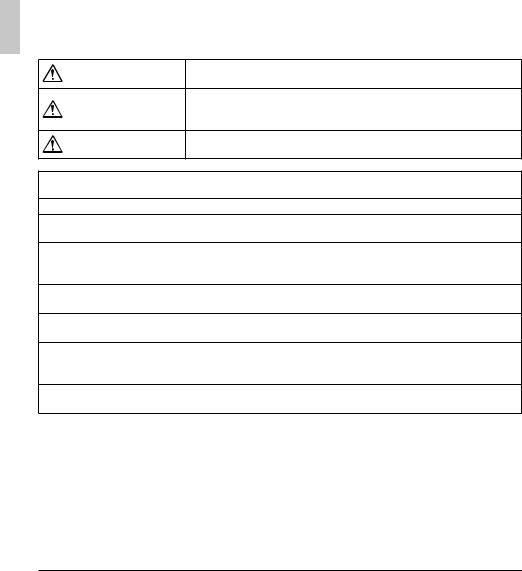
Meanings of WARNING, CAUTION, and NOTE Symbols.
WARNING |
Indicates a potentially hazardous situation which, if not avoided, could |
result in death or serious injury. |
Indicates a potentially hazardous situation which, if not avoided, may CAUTION result in minor or moderate injury.
It may also be used to alert against unsafe practices.
NOTE |
Indicates situations that may result in equipment or property-damage |
accidents only. |
 WARNING
Only qualified personnel must carry out the installation work.
Consult your Daikin dealer regarding relocation and reinstallation of the remote controller. Improper installation work may result in electric shocks or fire.
Electrical work must be performed in accordance with relevant local and national regulations and with instructions in this installation manual.
Improper installation may cause electrical shocks or fire.
Use only specified accessories and parts for installation work.
Failure to use specified parts may result in electric shocks, fire, or the unit falling.
Do not disassemble, reconstruct, or repair.
Electric shock or fire may occur.
Make sure that all wiring is secured, that specified wires are used, and that no external forces act on the terminal connections or wires.
Improper connections or installation may result in fire.
Before touching electrical parts, confirm the power-off to the unit.
2 |
English |
 CAUTION
Keep water out of the remote controller.
To avoid electric shock due to entry of water or insects, fill the wiring through-hole with putty. Do not wash the remote controller with water as it may result in electrical shocks or fire.
Do not touch the remote controller buttons with wet fingers.
Touching the buttons with wet fingers can cause an electric shock.
Do not install the remote controller in the following locations:
(a)Where a mineral oil mist or oil spray or vapor is produced, for example, in a kitchen. Plastic parts may deteriorate.
(b)Where corrosive gas, such as sulfurous acid gas, is produced.
(c)Near machinery emitting electromagnetic waves.
Electromagnetic waves may disturb the operation of the control system and cause the unit to malfunction.
(d)Where flammable gas may leak, where there is carbon fiber or ignitable dust suspensions in the air, or where volatile flammables such as thinner or gasoline are handled.
Operating the unit in such conditions can cause a fire.
(e)High temperature area or direct flame. Overheating and/or fire can occur.
(f)Moist area, where there is exposure to water. If water enters the inside of the remote controller, it may cause electric shock and electrical components may fail.
 NOTE
NOTE
Install the control wires for the indoor and the remote controller at least 3.5 feet (1 meter) away from televisions or radios to prevent image interference or noise. Depending on the radio waves, a distance of 3.5 feet (1 meter) may not be sufficient to eliminate the noise.
When remote controller’s temperature sensor is used, select the installation location as per the following:
●A place where average temperature in the room can be detected.
●A place where it is not exposed to direct sunlight.
●A place where it is far away from any heat source.
●A place where it is not affected directly by outside air.
English |
3 |
2. Accessories
The following accessories are included.
Drywall screw Drywall anchor |
Wire tie |
Operation |
Installation |
Wiring retainer |
|||||||
manual |
manual |
||||||||||
|
|
|
|
|
|||||||
|
|
|
|
|
|
|
|
|
|
|
|
|
|
|
|
|
|
|
|
|
|
|
|
|
|
|
|
|
|
|
|
|
|
|
|
|
|
|
|
|
|
|
|
|
|
|
|
(2 pcs.) |
(2 pcs.) |
(1 pc.) |
(1 pc.) |
(1 pc.) |
(1 pc.) |
3. Remote Controller Installation Procedure
3-1 Determine where to install the remote controller.
Make sure to follow the Safety Considerations when determining the location.
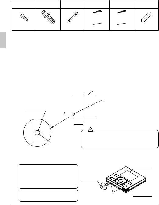
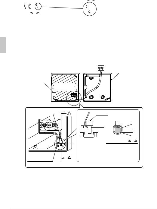
3-2 If the control wire for the remote controller is to be routed from the rear, consider the location of the access hole in the lower case for making a hole in the wall.
[Unit : inch] External view of the remote controller
Lower case
Through-hole
1-9/16


ΦΦ5/16-3/8
Align the center of the wall hole with the center of the access hole on the controller lower case when planning the installation.
|
|
1-15/16 |
|
|
|
|
|
|
NOTE |
|
|
|
|
|
|
|
|
Access |
|
If the hole size is too large or not in the proper |
|||
|
location, it may be seen after the remote |
||||
hole |
|
|
|||
|
controller is installed. |
||||
ΦΦ5/16-3/8 |
|
||||
|
|
|
|
||
3-3 Remove upper case.
Insert a screwdriver in the recess of lower case to remove the upper case (2 points).
Remote controller printed-circuit board is installed on the upper case. Be careful not to damage the printed-circuit board with the screwdriver.
Be careful not to let dust or moisture touch the printed-circuit board.
Upper case
Screwdriver
Insert and twist the screwdriver  Lower case lightly for removal.
4 |
English |
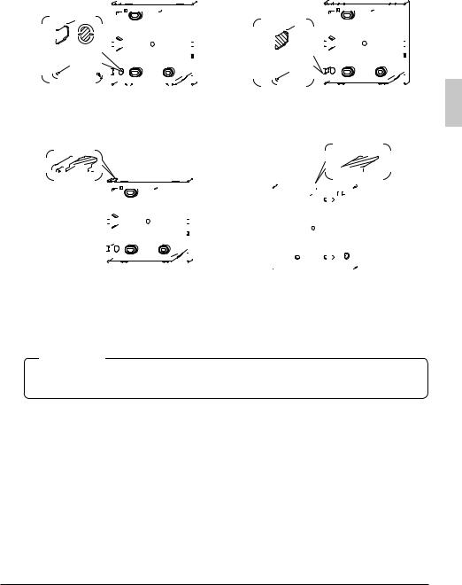
3-4 Determine the location where the wiring will enter the remote controller (back, left side, top left, top center).
3-4-1 Back outlet |
|
|
|
|
|
|
|
|
|
|
3-4-2 Left outlet |
|
|
|
|
|
|
|
|
|
|
|
|
|
|
|
|||||||||||||||||||||||||||||||||||||||||
|
|
|
|
|
|
|
|
|
|
|
|
|
|
|
|
|
|
|
|
|
|
|
|
|
|
|
|
|
|
|
|
|
|
|
|
|
|
|
|
|
|
|
|
|
|
|
|
|
|
|
|
|
|
|
|
|
|
|
|
|
|
|
|
|
|
|
|
|
|
|
|
|
|
|
|
|
|
|
|
|
|
|
|
|
|
|
|
|
|
|
|
|
|
|
|
|
|
|
|
|
|
|
|
|
|
|
|
|
|
|
|
|
|
|
|
|
|
|
|
|
|
|
|
|
|
|
|
|
|
|
|
|
|
|
|
|
|
|
|
|
|
|
|
|
|
|
|
|
|
|
|
|
|
|
|
|
|
|
|
|
|
|
|
|
|
|
|
|
|
|
|
|
|
|
|
|
|
|
|
|
|
|
|
|
|
|
|
|
|
|
|
|
|
|
|
|
|
|
|
|
|
|
|
|
|
|
|
|
|
|
|
|
|
|
|
|
|
|
|
|
|
|
|
|
|
|
|
|
|
|
|
|
|
|
|
|
|
|
|
|
|
|
|
|
|
|
|
|
|
|
|
|
|
|
|
|
|
|
|
|
|
|
|
|
|
|
|
|
|
|
|
Cut off resin area (notched area).
Cut the plastic at the notched area and remove any remaining burrs.
3-4-3 Top left outlet |
3-4-4 Top center outlet |
|
|
|
||||||||||||||||||||||||||||||||||||||||||||
|
|
|
|
|
|
|
|
|
|
|
|
|
|
|
|
|
|
|
|
|
|
|
|
|
|
|
|
|
|
|
|
|
|
|
|
|
|
|
|
|
|
|
|
|
|
|
|
|
|
|
|
|
|
|
|
|
|
|
|
|
|
|
|
|
|
|
|
|
|
|
|
|
|
|
|
|
|
|
|
|
|
|
|
|
|
|
|
|
|
|
|
|
|
|
|
|
|
|
|
|
|
|
|
|
|
|
|
|
|
|
|
|
|
|
|
|
|
|
|
|
|
|
|
|
|
|
|
|
|
|
|
|
|
|
|
|
|
|
|
|
|
|
|
|
|
|
|
|
|
|
|
|
|
|
|
|
|
|
|
|
|
|
|
|
|
|
|
|
|
|
|
|
|
|
|
|
|
|
|
|
|
|
|
|
|
|
|
|
|
|
|
|
|
|
|
|
|
|
|
|
|
|
|
|
|
|
|
|
|
|
|
|
|
|
|
|
|
|
|
|
|
|
|
|
|
|
|
|
|
|
|
|
|
|
|
|
|
|
|
|
|
|
|
|
|
|
|
|
|
|
|
|
|
|
|
|
|
|
|
|
|
|
|
|
|
|
|
|
|
|
|
|
|
|
|
|
|
|
|
|
|
|
|
|
|
|
|
|
|
|
|
|
|
|
|
|
|
|
|
|
|
|
|
|
|
|
|
|
|
|
|
|
|
|
|
|
|
|
|
|
|
|
|
|
|
|
|
|
|
|
|
|
|
|
|
|
|
|
|
|
|
|
|
|
|
|
|
|
|
|
|
|
|
|
|
|
|
|
|
|
|
|
|
|
|
|
|
|
|
|
|
|
|
|
|
|
|
|
|
|
|
|
|
|
|
|
|
|
|
|
|
|
|
|
|
|
|
|
|
|
|
|
|
|
|
|
|
|
|
|
|
|
|
|
|
|
|
|
|
|
|
|
|
|
|
|
|
|
|
|
|
|
|
|
|
|
|
|
|
|
|
|
|
|
|
|
|
|
|
|
|
|
|
|
|
|
|
|
|
|
|
|
|
|
|
|
|
|
|
|
|
|
|
|
|
|
|
|
|
|
|
|
|
|
|
|
|
|
|
|
|
|
|
|
|
|
|
|
|
|
|
|
|
|
|
|
|
|
|
|
|
|
|
|
|
|
|
|
|
|
|
|
|
|
|
|
|
|
|
|
|
|
|
|
|
|
|
|
|
|
|
|
|
|
|
|
|
|
|
|
|
|
|
|
|
|
|
|
|
|
|
|
|
|
|
|
|
|
|
|
|
|
|
|
|
|
|
|
|
|
|
|
|
|
|
|
|
|
|
|
|
|
|
|
|
|
|
|
|
|
|
|
|
|
|
|
|
|
|
|
|
|
|
|
|
|
|
|
|
|
|
|
|
|
|
|
|
|
|
|
|
|
|
|
|
|
|
|
|
|
|
|
|
|
|
|
|
|
|
|
|
|
|
|
|
|
|
|
|
|
|
|
|
|
|
|
|
|
|
|
|
|
|
|
|
|
|
|
|
|
|
|
|
|
|
Cut the plastic at the notched area and remove any remaining burrs.
Cut the plastic at the notched area and remove any remaining burrs.
3-5 Install wiring.
 NOTE
NOTE
1.Switch box and control wiring are filed supplied.
2.Do not touch the remote controller printed-circuit board.
Wiring Specifications
Wiring Type |
Non-shielded, 2-conductor, stranded copper wire |
Wiring Size |
AWG-18 |
Wiring Length |
Maximum 1640 feet (500m) |
English |
5 |
Prepare the wiring for connection to the remote controller following these instructions:
|
|
|
|
|
|
|
|
|
|
Approx. 3/8 inch |
|
|
|
|
|
|
|
|
|
|
|
To simplify the wiring, maintain |
|
|
|
|
|
|
|
|
|
|
|
||
|
|
|
|
Remove the wire jacket |
|
|
|
|
|
a 3/8in difference between the |
|
|
|
|
|
|
|
|
|
|
|||
|
|
|
|
|
|
|
|
|
length of the two conductors. |
||
|
|
|
|
and insulation |
Cutting guideline |
||||||
|
|
|
|
|
|||||||
Length of jacket to be removed:
●Approx. 6 inch for top left outlet
●Approx. 8 inch for top center outlet
Connect the terminals (P/P1, N/P2) of the remote controller to the terminals (P1, P2) of the indoor unit. (P1 and P2 are not polarity sensitive.)
3-5-1 Back outlet
Indoor unit
P1P2
Lower case
Upper case
Printed-circuit 
 board
board 

Wire tie
Wire attachment point
Wire tie
Cross-section |
- |
Secure the wire at the attachment point by using furnished wire tie.
<Wire attachment guideline>
6 |
English |

3-5-2 Left outlet |
|
|
|
Indoor unit |
|
|
P1P2 |
|
|
|
Lower case |
Upper case |
|
|
Printed-circuit |
|
|
board |
|
|
3-5-3 Top left outlet |
|
|
Wiring retainer |
Upper case |
|
Wiring retainer |
||
Wire |
|
As shown to the left, |
|
|
install the furnished |
|
|
wiring retainer to |
Cross-section |
- |
prevent the wires |
from being pinched |
||
|
|
during installation. |
Indoor unit |
|
|
P1P2 |
|
|
|
|
Lower case |
Upper case |
|
|
Printed- |
|
|
circuit board |
|
|
3-5-4 Top center outlet |
|
|
Indoor unit |
|
|
|
P1P2 |
|
Wiring retainer |
|
|
|
|
Lower case |
Upper case |
|
|
Printed-circuit |
|
|
board |
|
|
English |
7 |
 NOTE
NOTE
●To prevent electrical noise and possible communication errors, avoid installing the remote controller wiring parallel to or in the vicinity of line voltage circuits.
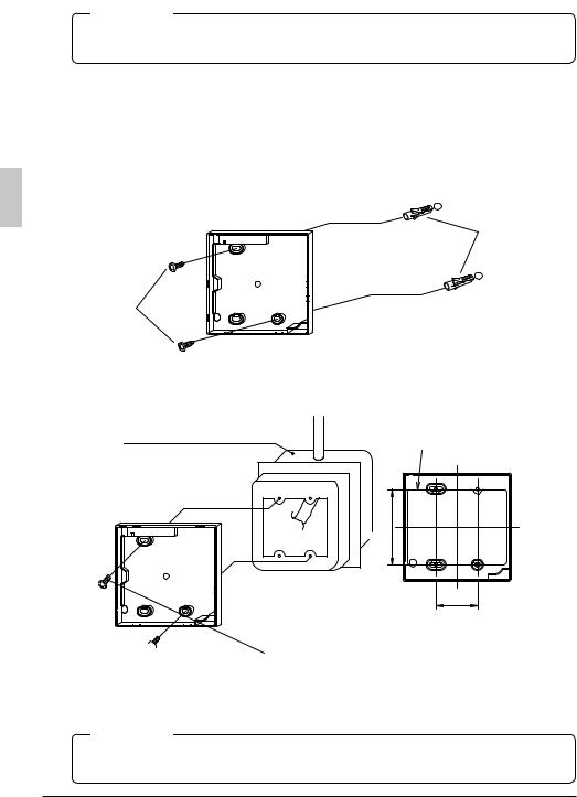
3-6 Installation procedure for the lower case.
When wiring the remote controller through the top center or rear access points, attachment of the wire to the lower case is required before it is wall mounted. Closely follow the wiring
procedures.
3-6-1 Wall installation
Secure by using furnished drywall anchors and screws (2 pcs.).
Drywall anchors
Drywall screws
3-6-2 Switch box installation
Secure by using field supplied machine screws (2 pcs.).
Switch box
(field supply) or
(use optional accessory KJB211A)
 5/16-3
[Unit : inch]
Switch box
1-13/16 |

 Machine screws (field supply) or
(use optional accessory KJB211A)
 NOTE
NOTE
●Install the control on a flat surface only.
●To prevent deformation of the lower case, avoid over-tightening the installation screws.
8 |
English |
3-7 Install the upper case.
●Align the upper case with tabs of the lower case (6 points), insert and install the upper case.
●Install the wiring with care to prevent pinching.
●Peel off the protective membrane which overlays the upper case.
|
|
|
|
|
|
|
|
|
|
|
|
|
|
|
|
|
|
|
|
|
|
|
|
|
|
|
|
|
|
|
|
|
|
|
|
|
|
|
|
|
|
|
|
|
|
|
|
|
|
|
|
|
|
|
|
|
|
|
|
|
|
|
|
|
|
|
|
|
|
|
|
|
|
|
|
|
|
|
|
|
|
|
|
|
|
|
|
|
|
|
|
|
|
|
|
|
|
|
|
|
|
|
|
|
|
|
|
|
|
|
|
|
|
|
|
|
|
|
|
|
|
|
|
|
|
|
|
|
|
|
|
|
|
|
|
|
|
|
|
|
|
|
|
|
|
|
|
|
|
|
|
|
|
|
|
|
|
|
|
|
|
|
|
|
|
|
|
|
|
|
|
|
|
|
|
|
|
|
|
|
|
|
|
|
|
|
|
|
|
|
|
|
|
|
|
|
|
|
|
|
|
|
|
|
|
|
|
|
|
|
|
|
|
|
|
|
|
|
|
|
|
|
|
|
|
|
|
|
|
|
|
|
|
|
|
|
|
|
|
|
|
|
|
|
|
|
|
|
|
|
|
|
|
|
|
|
|
|
|
|
|
|
|
|
|
|
|
|
|
|
|
|
|
|
|
|
|
|
|
|
|
|
|
|
|
|
|
|
|
|
|
|
|
|
|
|
|
|
|
|
|
|
|
|
|
|
|
|
|
|
|
|
|
|
|
|
|
|
|
|
|
|
|
|
|
|
|
|
|
|
|
|
|
|
|
|
|
|
|
|
|
English |
9 |
|
|||||||||||||||
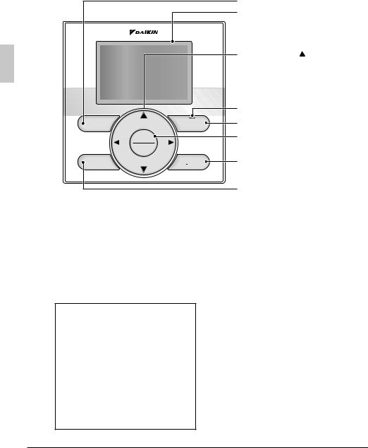
4.Functions and Menu Items of Remote Controller Buttons
4-1 Functions and menu items
Mode |
On/Off |
|
Menu |
|
OK |
Fan |
Cancel |
Speed |
(1) Operation mode selector button
(11) LCD (with backlight)
(4) Up button
(5)Down button 
(6)Right button 
(7)Left button 
(9)Operation lamp
(8)On/Off button
(3)Menu/OK button
(10)Cancel button
(1)Operation mode selector button
Used to change the mode.
(2)Fan speed control button
Used to change the fan control.
(3)Menu/OK button
●Used to access the main menu.
(For details of the main menu, see the operation manual.)
●Used to enter the item selected.
Main Menu
Airflow DirectionIndividual Airflow Direction
Ventilation
Schedule
Off Timer
Celsius / Fahrenheit
Filter Auto Clean
Maintenance Information Configuration
Current Settings
Clock & Calendar
Daylight Saving Time
Language
Depending on connected model
(2)Fan speed control button
(4)Up button
●Used to raise the setpoint temperature.
●The previous menu items will be highlighted.
(The highlighted items will be scrolled continuously when the button is pressed continuously.)
●Used to change the selected item.
(5)Down button
●Used to lower the setpoint temperature.
●Items below the currently selected item will be highlighted.
(The highlighted items will be scrolled continuously when the button is pressed continuously.)
●Used to change the selected item.
(6)Right button
●Used to highlight items to the right of the currently selected item.
●Display contents are changed to next screen per page.
10 |
English |
(7)Left button 
●Used to highlight items to the left of the currently selected item.
●Display contents are changed to previous screen per page.
(8)On/Off button
Press once to operate, and press once again to stop.
(9)Operation lamp
Green lamp lights up during operation. The lamp will flash if a malfunction occurs.
(10)Cancel button
●Used to return to the previous screen.
●Press and hold this button for 4 seconds or longer to display service settings menu.
(11)LCD (with backlight)
The backlight will illuminate for approximately 30 seconds by pressing any operation button.
Service Settings menu
Test Operation Maintenance Contact Field Settings
Energy Saving Options Prohibit Function
Min Setpoints DifferentialOutdoor unit AirNet Address Error History
Indoor Unit Status
Outdoor Unit Status Forced Fan ON
Switch Main Sub Controller Filter IndicatorBrush/Filter Ind.
Disable Filter Auto Clean
Depending on connected model
 NOTE
NOTE
●Operate the button while the backlight is illuminated.
●When one indoor unit is controlled by two remote controllers (main / sub) only the first controller to be accessed by the user will illuminate it’s backlight.
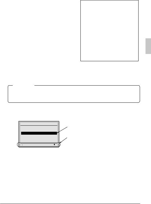
4-2 Button menu display descriptions
<Service settings menu screen>
Service Settings |
1/3 |
Test Operation
Maintenance Contact
Field Settings
Energy Saving Options
Prohibit Function
Min Setpoints Differential
Setting
Highlighted display (selected items)
In the highlighted display (selected items) setting screen, button operation descriptions are displayed.
English |
11 |
5. Power-on
●Check for completion of indoor/outdoor unit wiring.
●Ensure that covers have been replaced on electrical component boxes for both indoor and outdoor units prior to restoring power.
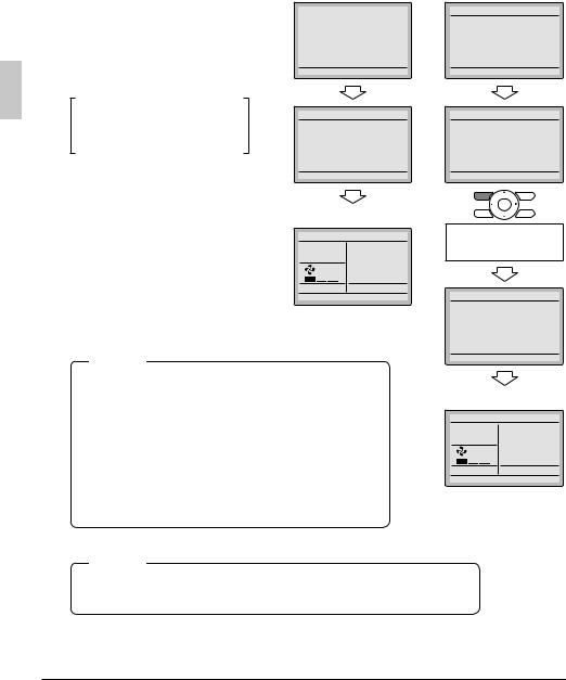
5-1 The following message is displayed after power-on.
Checking the connection. Please stand by.
When the above message is displayed, the backlight will not be ON.
In the case that 1 indoor unit is controlled by
2 remote controllers:
Make sure to set the sub remote controller when the above message is displayed. Hold Mode button for 4 seconds or longer to set.
When the display is changed from “Main RC” to “Sub RC” the setting is completed.
5-2 Basic screen is displayed.
<Main remote controller>
5-1 Off reminder Timer |
5-1 |
|
|
|
|
Checking the connection.
Please stand by.
Main RC
Error Code U5
Checking the connection.
Please stand by.
Main RC
<Basic screen>
5-2
Fan Set temperature
28°C
ReturnPress the menu button
NOTE
If sub remote controller is not set at power-on in the case of one indoor unit controlled by two remote controllers,
Error Code: U5 is displayed in the connection checking 5-2 screen.
Select the sub remote controller by pressing Mode button of either one of the remote controllers for 4 seconds or longer.
If the basic screen is not displayed in 2 minutes after the “Sub RC” is displayed, shut off the power supply and check the wiring.
<Sub remote controller>
Off reminder Timer
Checking the connection.
Please stand by.
Main RC
Error Code U5
Checking the connection.
Please stand by.
Main RC
Press and hold 4 seconds or longer Mode button of sub remote controller side.
Off reminder Timer
Checking the connection.
Please stand by.
Sub RC
<Basic screen>
Fan Set temperature
28°C
ReturnPress the menu button
NOTE
When selecting a different language, refer to Chapter 12. Language. (See page 21.)
12 |
English |
6. Field Settings
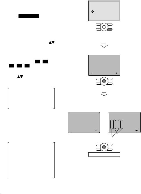
6-1 Press and hold Cancel button for
4 seconds or longer. Service settings menu is displayed.
6-2 Select Field Settings in the Service Settings menu, and press Menu/OK button.
Field settings screen is displayed.
6-3 Highlight the mode, and select desired “Mode No.” by using (Up/Down) button.
6-4 In the case of setting per indoor unit during group control (When Mode No. such as 20 , 21 , 22 , 23 , 25 are selected), highlight the unit No. and select “Indoor unit No.” to be set by using (Up/Down) button. (In the case of group setting, this operation is not needed.)
In the case of individual setting per indoor unit, current settings are displayed. And, SECOND CODE NO. “ - ” means no function.
6-5 Highlight SECOND CODE NO. of the FIRST CODE NO. to be changed, and select desired “SECOND CODE NO.” by using  (Up/Down) button. Multiple identical mode number settings are available.
In the case of setting for all indoor units in the remote control group, available SECOND CODE NO. is displayed as “ ” which means it can be changed.
When SECOND CODE NO. is displayed as “ - ”, there is no function.
<Basic screen>
6-1
|
|
|
|
|
|
|
Fan |
|
Set temperature |
|
|
|
|
|
|
|||||||||
|
|
|
|
|
|
|
|
|
|
|
|
|
|
28°C |
|
|
|
|
|
|
||||
|
|
|
|
|
|
|
|
|
|
|
|
|
|
|
|
|
|
|
|
|||||
|
|
|
|
|
|
|
|
|
|
|
|
|
|
|
|
|
|
|
|
|
|
|
|
|
|
|
|
|
|
|
|
|
|
|
|
|
|
|
|
|
|
|
|
|
|
|
|
||
|
|
|
|
|
|
|
ReturnPress the menu button |
|
|
|
|
|
|
|||||||||||
|
|
|
|
|
|
|
|
|
|
|
|
|
|
|
|
|
|
|
|
|
|
|
||
|
|
|
|
|
|
|
|
|
|
|
|
|
|
|
|
|
|
|||||||
|
|
|
|
|
|
Press and hold Cancel |
|
|
|
|
|
|
||||||||||||
|
|
|
|
|
|
button for 4 seconds or |
|
|
|
|
|
|
||||||||||||
|
|
|
|
|
|
longer during backlight lit. |
|
|
|
|
|
|
||||||||||||
|
|
|
|
|
<Service settings menu screen> |
|
|
|
|
|||||||||||||||
|
|
|
|
|
|
|
|
|
||||||||||||||||
|
|
|
6-2 |
|
|
|
|
|
|
|
|
|
|
|
|
|
||||||||
|
|
|
|
Service Settings |
1/3 |
|
|
|
|
|
|
|||||||||||||
|
|
|
|
|
|
|
Test Operation |
|
|
|
|
|
|
|
|
|
|
|||||||
|
|
|
|
|
|
|
Maintenance Contact |
|
|
|
|
|
|
|
|
|
|
|||||||
|
|
|
|
|
|
|
Field Settings |
|
|
|
|
|
|
|
|
|
|
|
|
|||||
|
|
|
|
|
|
|
Energy Saving Options |
|
|
|
|
|
|
|
|
|
|
|||||||
|
|
|
|
|
|
|
Prohibit Function |
|
|
|
|
|
|
|
|
|
|
|||||||
|
|
|
|
|
|
|
Min Setpoints Differential |
|
|
|
|
|
|
|||||||||||
|
|
|
|
|
|
|
|
|
|
|
|
|
Setting |
|
|
|
|
|
|
|
|
|
|
|
|
|
|
|
|
|
|
|
|
|
|
|
|
|
|
|
|
||||||||
|
|
|
|
|
|
Press Menu/OK button. |
|
|
|
|
|
|
||||||||||||
|
|
|
|
|
<Service settings screen> |
|
|
|
|
|||||||||||||||
|
In the case of individual |
|
|
In the case of group total |
|
|||||||||||||||||||
|
|
setting per indoor unit |
|
|
|
|
|
|
|
setting |
|
|
|
|||||||||||
6-3 |
|
|
|
|
|
|
|
|
|
|
|
6-3 |
|
|
|
|
|
|
|
|
|
|||
|
Field Settings |
|
|
|
|
|
|
|
|
|
Field Settings |
|
|
|
|
|||||||||
6-4 |
|
0 |
|
20 |
|
|
|
|
|
|
|
|
6-5 |
|
0 |
|
|
|
10 |
|
|
|
||
|
|
Unit No |
Mode |
|
|
|
|
|
|
|
|
|
Unit No |
|
Mode |
|
|
|
||||||
6-5 |
|
0–01 |
1–01 |
|
2–02 |
3–01 |
|
|
|
|
|
0– |
01 |
|
1– |
2– |
3– |
|
|
|||||
|
|
|
|
|
|
|
||||||||||||||||||
|
|
4––– |
5––– |
|
6––– |
7––– |
|
|
|
|
|
4––– |
|
5––– |
6––– |
7––– |
|
|
||||||
|
|
8––– |
9––– |
|
10––– |
11––– |
|
|
|
|
8––– |
9––– |
10––– |
11––– |
|
|
||||||||
|
|
12––– |
13––– |
|
14––– |
15––– |
|
|
|
|
12––– |
13––– |
14––– |
15––– |
|
|
||||||||
|
|
|
Setting |
|
|
|
|
|
|
|
|
|
|
|
|
|
Setting |
|
|
|
||||
SECOND CODE NO.
FIRST CODE (SW) NO.
Press Menu/OK button.
English |
13 |
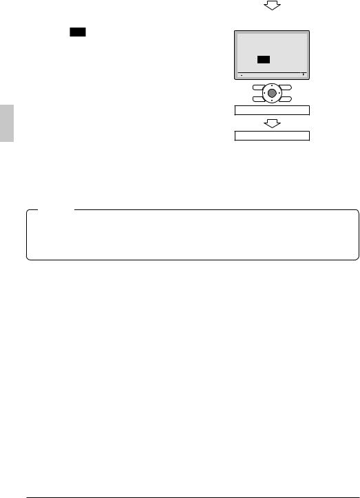
6-6 Press Menu/OK button. Setting confirmation screen is displayed.
6-7 Select Yes and press Menu/OK button. Setting details are determined and field settings screen returns.
6-8 In the case of multiple setting changes, repeat “6-3” to “6-7”.
6-9 After all setting changes are completed, press Cancel button twice.
6-10 Backlight goes out, and [Checking the connection. Please stand by.] is displayed for initialization. After the initialization, the basic screen returns.
<Setting confirmation screen>
6-6 |
Field Settings |
6-7 |
Save the settings? |
Yes No
Setting
Press Menu/OK button.
Setting confirmation
NOTE
●Installation of optional accessories on the indoor unit may require changes to field settings. See the manual of the optional accessory.
●For field setting details related to the indoor unit, see installation manual shipped with the indoor unit.
Mode |
First |
|
|
Second Code No. (Note 2) |
|
||
|
(Items in bold are factory default settings) |
|
|||||
No. |
Code |
Description |
|
||||
(Note 1) |
No. |
|
01 |
02 |
03 |
|
04 |
|
|
|
|
|
|
|
|
|
|
|
The return air |
The remote |
|
|
|
|
|
|
thermistor is |
controller |
Only the |
|
|
|
|
Priority of thermistor |
primary and the |
thermistor is not |
remote |
|
|
|
2 |
sensors for space |
remote |
utilized. Only |
controller |
|
———— |
|
|
temperature control |
controller |
the return air |
thermistor will |
|
|
10 (20) |
|
|
thermistor is |
thermistor will |
be utilized. |
|
|
|
|
|
secondary. |
be utilized. |
|
|
|
|
|
Room temperature |
|
Thermistor |
|
|
|
|
|
Return air |
designated by |
|
|
|
|
|
5 |
value reported to |
———— |
|
———— |
||
|
thermistor |
10-2 above |
|
||||
|
|
multizone controllers |
|
|
|
||
|
|
|
(Note 3) |
|
|
|
|
|
|
|
|
|
|
|
|
|
|
Thermo-on/off |
|
|
|
|
|
12 (22) |
2 |
deadband |
2F (1C) |
1F (0.5C) |
———— |
|
———— |
|
|
(Note 4) |
|
|
|
|
|
|
|
Thermistor sensor for |
|
Utilize the remote |
|
|
|
|
|
auto changeover and |
Utilize the return |
|
|
|
|
|
1 |
controller |
———— |
|
———— |
||
|
setback control by the |
air thermistor |
|
||||
1c |
|
thermistor |
|
|
|
||
|
remote controller |
|
|
|
|
||
|
|
|
|
|
|
|
|
|
3 |
Access permission |
Level 2 |
Level 3 |
———— |
|
———— |
|
level setting |
|
|||||
|
|
|
|
|
|
|
|
1e |
2 |
Setback availability |
N/A |
Heat only |
Cool only |
|
Cool/Heat |
14 |
English |
Notes) 1. Field settings are normally applied to the entire remote control group, however if individual indoor units in the remote control group require specific settings or for confirmation that settings have been established, utilize the mode number in parenthesis.
2.Any features not supported by the connected indoor unit will not be displayed.
3.When mode 10-2-01 is selected, only the return air temperature value is reported to the multizone controller.
4.The actual default deadband value will depend upon the indoor unit model.
7.Test Operation
Also see installation manuals furnished with the indoor unit and the outdoor unit.
●Verify that the wiring of the indoor unit and the outdoor unit is completed.
●Ensure that covers have been replaced on electrical component boxes for both indoor and outdoor units prior to restoring power.
●After refrigerant piping, drain piping and electric wiring are completed, clean inside of the indoor unit and decorative panel.
●Perform the test operation according to following procedure.
●To protect the compressor, apply power to the outdoor unit at least 6 hours prior to test operation.
●Set the remote controller display mode to standard or detailed display mode. Refer to Operation Manual for the setting method.
Notes for backlight
●The backlight will be ON for 30 seconds by pressing any button.
●The initial push of the button will only turn on the backlight. While the backlight is turned on, the buttons assigned functionality will be available.
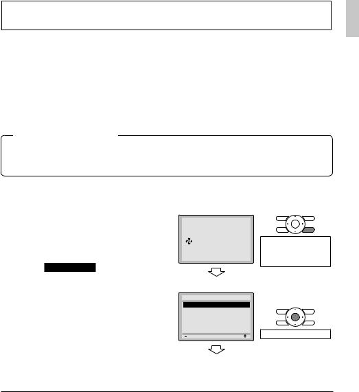
7-1 Set the operation mode to cooling by using the remote controller.
7-2 Press and hold Cancel button for
4 seconds or longer. Service settings menu is displayed.
7-3 Select Test Operation in the service settings menu, and press Menu/OK button. Basic screen returns and Test Operation is displayed at the button.
<Basic screen>
7-1
7-2 |
|
Cool |
|
|
Set to68F |
||||
|
|
|
|
|
|
|
|
||
|
|
|
|
|
|
|
|
|
|
|
|
|
|
|
|
|
|
|
|
|
|
|
|
|
|
|
|
|
|
|
|
Return |
Clean the filter |
||||||
Press and hold Cancel button for 4 seconds or longer while the backlight is on.
<Service settings menu screen>
7-3 |
Service Settings |
1/3 |
|
Test Operation |
|
|
Maintenance Contact |
|
|
Field Settings |
|
|
Energy Saving Options |
|
|
Prohibit Function |
|
|
Min Setpoints Differential |
Press Menu/OK button. |
|
Setting |
English |
15 |
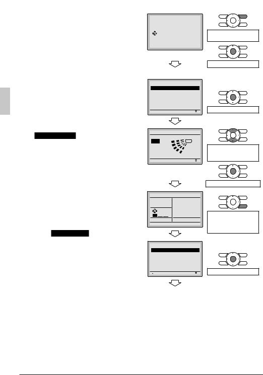
7-4 Press On/Off button within 10 seconds, and the test operation starts. Monitor the operation of the indoor unit for a minimum of 10 minutes. During test operation, the indoor unit will continue to cool regardless of the temperature setpoint and room temperature.
Note) In the case of above-men- tioned procedures 7-3 and
7-4 in reverse order, test operation can start as well.
7-5 Press Menu/OK button in the basic screen. Main menu is displayed.
7-6 In the case of a model having airflow direction function, select
Airflow Direction in the main menu and check that airflow direction is actuated according to the setting. For operation of airflow direction setting, see the operation manual.
7-7 After the operation of airflow direction is confirmed, press Menu/OK button. Basic screen returns.
7-8 Press and hold Cancel button for
4 seconds or longer in the basic screen.
Service settings menu is displayed.
7-9 Select Test Operation in the service settings menu, and press Menu/OK button. Basic screen returns and normal operation is conducted.
Note) The test operation will automatically finish in 30 minutes.
7-10 Check the functions according to the operation manual.
7-11 When the decorative panel is not installed, shut off the power supply after the test operation finishes.
●If construction activities are planned within the space following the test operation procedure, recommend to the customer that the indoor unit is not operated to prevent contamination from paints, drywall dust and other airborne materials.
7-4
7-5 |
|
Cool |
Set temperature |
||||||
|
|
|
|
|
|
|
|
|
28°C |
|
|
|
|
|
|
|
|
|
|
|
|
|
|
|
|
|
|
|
|
|
|
|
|
|
|
|
|
|
|
|
Test Operation |
|
|
||||||
|
<Main menu screen> |
||||||||
7-6 |
Main Menu |
1/3 |
|||||||
Airflow Direction
Individual Airflow Direction
Ventilation
Schedule
Off Timer
Celsius / Fahrenheit
Setting
7-7 Airflow Direction
Swing
Setting
7-8
Cool Set temperature
28°C
Test Operation
7-9 Service Settings |
1/3 |
|
|
|
|
Test Operation
Maintenance Contact
Field Settings
Energy Saving Options
Prohibit Function
Min Setpoints Differential
Setting
<Basic screen>
Press On/Off button (within 10 seconds).
Press Menu/OK button.
Press Menu/OK button.
Change the airflow direction by using (Up/Down) button.
Press Menu/OK button.
Press and hold Cancel button for 4 seconds or longer while the backlight is on.
Press Menu/OK button.
16 |
English |
 NOTE
NOTE
●If operation is not possible due to a malfunction, refer to following Failure diagnosis method .
●After the test operation finishes, check whether the error code history is displayed on the maintenance information screen of the main menu according to the following procedure.
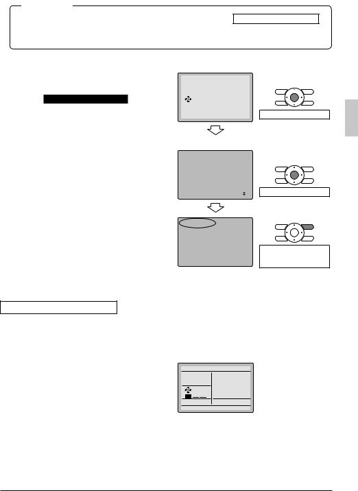
7-12 Press Menu/OK button in the basic screen. main menu screen is displayed.
7-13 Select Maintenance Information in the main menu, and press Menu/OK button.
7-14 Maintenance information screen is displayed. Check whether the error code history is displayed on the screen.
If no error code history is displayed following this procedure the system has normally completed the test operation mode.
7-15 If the error code history is displayed, conduct the failure diagnosis referring to <Error code list> in the installation manual of the indoor unit.
After the failure diagnosis finishes, press and hold On/Off button for 4 seconds or longer in the mainte-
nance information screen to erase the error code history.
<Basic screen>
7-12
|
Cool |
Set to68F |
|||||
|
|
|
|
|
|
|
|
|
|
|
|
|
|
|
|
|
|
|
|
|
|
|
|
|
|
|
|
|
|
|
|
|
Return Clean the filter |
||||||
<Main menu screen> |
|||||||
7-13 |
|
|
Main Menu |
2/3 |
|
|
Filter Auto Clean |
|
|
Maintenance Information |
|
|
Configuration |
|
|
Current Setting |
|
|
Clock & Calendar |
|
|
Daylight Saving Timer |
|
|
Setting |
|
7-14 |
|
|
Error Code:U5 |
|
|
7-15 |
Contact Info |
|
0123–456–7890 |
|
|
|
Indoor Model |
–––/000 |
|
Outdoor Model |
–––/000 |
|
|
|
Press Menu/OK button.
Press Menu/OK button.
Press and hold On/Off button for 4 seconds or longer during backlight lit.
Failure diagnosis method
●Whenever the remote controller display is blank or displays [Checking the connection. Please stand by.], troubleshoot the system with the items in the Description column of the following table.
●If an error occurs, CODE is displayed on the LCD as shown to the right.
Conduct the failure analysis referring to <Error code list> in the installation manual of the indoor unit.
When the unit No. which detected the error during group control is confirmed, refer to Chapter 8: Procedure
for Checking Error History.
Cool Set temperature
28°C
Test Operat. CODE : U5
English |
17 |
Remote controller display |
Description |
|
|
●Power outage, power voltage error or open-phase |
|
|
●Incorrect wiring (between indoor and outdoor units) |
|
No display |
●Indoor PC-board assembly failure |
|
●Remote controller wiring not connected |
||
|
||
|
●Remote controller failure |
|
|
●Open fuse or tripped circuit breaker (outdoor unit) |
|
Checking the connection. |
●Indoor PC-board assembly failure |
|
Please stand by. |
●Wrong wiring (between indoor and outdoor units) |
[Checking the connection. Please stand by.] will be displayed for up to 90 seconds following the application of power to the indoor unit. This is normal and does not indicate a malfunction.
8.Procedure for Checking Error History
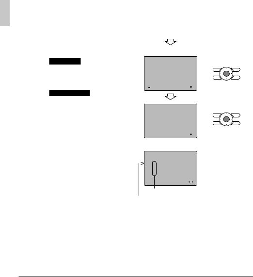
8-1 Press and hold the Cancel button for 4 seconds or longer in the basic screen. Service settings menu is displayed.
8-1 <Basic screen>
<Service settings menu screen>
8-2 Select Error History in the service settings menu, and press Menu/OK button. The error history menu screen is displayed.
8-3 Select RC Error History in the error history menu, and press Menu/OK button.
Error codes and unit No. can be confirmed in the RC error history screen.
8-4 In the error history, the 10 most recent items are displayed in order of occurrence.
8-5 Press Cancel button in the RC error history screen 3 times.
The basic screen returns.
8-2 |
|
|
|
|
|
|
|||
Service Settings |
2/3 |
|
|
||||||
|
|
|
|
Outdoor unit AirNet Address |
|
|
|
||
|
|
|
|
Error History |
|
|
|
|
|
|
|
|
|
Indoor Unit Status |
|
|
|
||
|
|
|
|
Outdoor Unit Status |
|
|
|
||
|
|
|
|
Forced Fan ON |
|
|
|
||
|
|
|
|
Switch Main Sub Controller |
|
|
|
||
|
|
|
|
|
|
Press Menu/OK button. |
|||
|
|
|
|
|
|
Setting |
|
|
|
8-3 |
|
|
|
|
|
|
|
||
|
Error History |
|
2/2 |
|
|
||||
|
|
|
|
RC Error History |
|
|
|
||
|
|
|
|
Indoor unit Error History |
|
|
|
||
|
|
|
|
|
|
|
|
|
|
|
|
|
|
|
|
|
|
|
Press Menu/OK button. |
8-4 |
|
|
|
|
Setting |
|
|
|
|
|
|
|
|
|
|
|
|||
|
|
|
|
|
|
|
|
||
8-5 |
|
|
RC Error History |
1/3 |
|
|
|||
|
|
Unit Error |
Date |
Time |
|
|
|||
|
|
|
|
01 –– |
–– |
–– / –– / –– |
––:–– |
|
|
|
|
|
|
|
|
||||
|
|
|
|
02 –– |
–– |
–– / –– / –– |
––:–– |
|
|
|
|
|
|
03 –– |
–– |
–– / –– / –– |
––:–– |
|
|
|
|
|
|
04 –– |
–– |
–– / –– / –– |
––:–– |
|
|
|
|
|
|
|
|
|
|
|
|
|
|
|
|
|
|
Setting |
|
|
|
Unit No.
Latest record
18 |
English |
9.Adding Maintenance Contact Information
● Registration of the maintenance contact.
9-1 Press and hold Cancel button for
4 seconds or longer in the basic screen.
Service settings menu is displayed.
9-1 <Basic screen>
<Service settings menu screen>
9-2 Select Maintenance Contact in the service settings menu, and press Menu/OK button. Maintenance contact menu screen is displayed.
9-3 Select Maintenance Contact , and
press Menu/OK button.
9-4 Enter the telephone number.
Scroll through the numbers by using (Up/Down) buttons. Start from the
left side. Blank digits should remain as “ - ”.
9-5 Press Menu/OK button. Setting confirmation screen is displayed.
9-6 Select Yes and press Menu/OK button.
Setting details are saved and service settings menu screen returns.
9-7 Press Cancel button once. The basic screen returns.
9-2 |
Service Settings |
1/3 |
|
Test Operation |
|
|
Maintenance Contact |
|
|
Field Settings |
|
|
Energy Saving Options |
|
|
Prohibit Function |
|
|
Min Setpoints Differential |
Press Menu/OK button. |
|
Setting |
9-3 Maintenance Contact
None
Maintenance Contact
Setting |
Press Menu/OK button. |
9-4 |
|
|
|
|
Maintenance Contact |
1/2 |
|||
|
|
|
––––––––––––––– |
|
|
|
– |
|
|
|
|
|
|
|
|
|
|
Setting |
|
9-5 |
|
Maintenance Contact |
1/2 |
|
0123–45–––––––––
Setting |
Press Menu/OK button. |
<Setting confirmation screen>
9-6 Maintenance Contact
Save the settings?
Yes No
Setting |
Press Menu/OK button. |
<Service settings menu screen>
English |
19 |
 Loading...