


OPERATING MANUAL
|
AUTO |
MON TUE WED THU FRI SAT SUN ALL |
||||
|
OVERRIDE |
12 |
|
|||
|
|
|
||||
|
|
|
12 |
12 |
|
|
DRY |
AUTO |
COOL |
HEAT |
FAN |
|
|
|
|
|
|
|
SET |
|
TURBO |
QUIET |
|
SWING |
SLEEP |
TEMP. |
|
|
|
|||||
MODE
|
TURBO |
SWING |
QUIET |
DELAY |
TIMER |
TIMER |
|
TIMER |
ON |
OFF |
SLEEP |

 FAN
FAN 
 ON / OFF
Operating Manual |
English |
|
Handset Wireless |
||
|
||
Mode D’emploi |
|
|
|
||
Français |
||
Combiné Câblé |
||
|
||
Bedienungsanleitung |
|
|
|
||
Deutsch |
||
Verdrahtetes Handgerät |
||
|
||
Manuale Di Funzionamento |
|
|
|
||
Italiano |
||
Ricevitore senza fili |
||
|
||
Manual De Instrucciones |
|
|
|
||
Español |
||
Auricular Inalámbrico |
||
|
||
Руководство По Зксплуатации |
|
|
|
||
Pycckий |
||
Беспроводное Дистанционное Управление |
||
|
||
Kullanım Kılavuzu |
|
|
|
||
Türkçe |
||
Kablosuz Kumanda |
||
|
||
|
|
OM-SLM9-0911(1)-DAIKIN
Part No.: R08019037014A


i

BRC51A61/62 Controller Indication
3
2
1
10
9
11
8
|
AUTO |
MON TUE WED THU FRI SAT SUN ALL |
||||
|
OVERRIDE |
12 |
|
|||
|
|
|
||||
|
|
|
12 |
12 |
|
|
DRY |
AUTO |
COOL |
HEAT |
FAN |
|
|
|
|
|
|
|
SET |
|
TURBO |
QUIET |
|
SWING |
SLEEP |
TEMP. |
|
MODE
|
TURBO |
SWING |
QUIET |
DELAY |
TIMER |
TIMER |
|
TIMER |
ON |
OFF |
SLEEP |
FAN |
ON / OFF |
4
5
6
7
12
13
NO |
KEY |
FUNCTION |
|
|
|
1. |
MODE |
Select operating Modes control (Cool/ Heat/ Auto/ Dry/ Fan) |
|
|
|
2. |
TURBO |
Activate/deactivate Turbo function |
|
|
|
3. |
SWING |
Activate/deactivate Swing control |
|
|
Hold Key to change Swing Mode |
|
|
|
4. |
QUIET |
Activate/deactivate Quiet function |
|
|
|
5. |
SET TEMP UP |
Increase set temperature in °C or °F |
|
|
|
6. |
SET TEMP DOWN |
Decrease set temperature in °C or °F |
|
|
|
7. |
SLEEP |
Activate/deactivate Sleep function |
|
|
|
8. |
OFF TIMER |
Enable/disable the Event 1 and 2 OFF TIMER setting mode |
|
|
|
9. |
ON TIMER |
Enable/disable the Event 1 and 2 ON TIMER setting mode |
|
|
|
10. |
DELAY TIMER |
Activate/deactivate delay timer |
|
|
|
11. |
FAN |
Select Fan speeds control (Auto/ High/ Med/ Low) |
|
|
|
12. |
ON/OFF |
On/Off the unit with overriding all the timer settings |
|
|
|
13. |
REAL TIME CLOCK (RTC) |
Enable/disable the Real Time Clock (RTC) setting mode |
|
|
|
NOTE:
Turbo and quiet function are for selected models only.
ii
OPERATING INSTRUCTION
1.1MODE Button
Press the MODE button to switch operation from COOL, HEAT*, AUTO*, DRY*, FAN. Check the display to see in which mode the control is set. *HEAT, AUTO and DRY are available for selected models only.
1.2TURBO Fan Speed
Press the TURBO key once to activate Turbo fan speed. Turbo symbol will be shown. To disable Turbo fan speed and back to previous fan speed, press the Turbo key once again. If user presses the FAN button or QUIET button or turn off the unit, the turbo speed will be disabled. This speed is only valid during COOL and HEAT mode for selected models.
1.3Automatic air swing
•Press the SWING  button to activate the automatic air swing function.
•To distribute the air to a specific direction, press the SWING  button and wait until the louver move to the desired direction and press the button once again.
Swing mode selection method (model dependent)
•Press SWING ( ) button for 4 seconds to enter field setting mode. While in field setting mode, it will only show SWING MODE (
 ).
).
•Press temperature  and
and  button to select SWING MODE (
 ) rotation from Swing Mode 1 to Swing Mode 3.
•There are 3 different SWING MODE, which are:
Swing mode 1 Swing mode 2 Swing mode 3
SWING MODE will not activate unless SWING is activated. Swing is indicated by the logo: 
• If no mode changes within 4 seconds, unit will operate according to the selected SWING MODE ( ).
).
1.4QUIET Fan Speed
Press the QUIET key once to activate Quiet fan speed. QUIET symbol will be shown. To disable Quiet fan speed and back to previous fan speed, press the QUIET key again. If user presses the FAN button or TURBO button or turn off the unit, the quiet speed will be disabled. This speed is only valid during COOL and HEAT mode for selected models.
1.5“ ” or “
 ” Set Temperature Button
Press the temperature button and set the temperature of your choice by pressing “ ” or “
 ” button once, temperature changes by 1°C or 1°F. The default temperature setting range is from 16°C to 30°C (60°F to 86°F). When the Option 20 - 30ºC is set, the temperature range limit is set to 20ºC to 30ºC (68°F to 86°F). Pressing both keys simultaneously will toggle the temperature setting between ºC and ºF. No temperature setting is allowed during FAN mode (No set temp display). There is no room temperature display.
1.6SLEEP Function
Press the SLEEP button to activate the sleep mode. SLEEP function is not available in DRY mode and FAN mode.
1.7“ON TIMER” and “OFF TIMER”
The unit has 2-event timer, namely Timer 1 and Timer 2, each event has an ON TIMER and an OFF TIMER. The key press activity for Timer ON and Timer OFF is shown on Table 1.1
<![endif]>Original Instruction ENGLISH
1

Table 1.1: Timer ON and Timer OFF key press and event sequence.
TIMER ON KEY |
TIMER OFF KEY |
||
|
|
|
|
ON Timer 1 |
ON Timer 2 |
OFF Timer 1 |
OFF Timer 2 |
|
|
|
|
Deactivated |
Deactivated |
Deactivated |
Deactivated |
Activated |
Deactivated |
Activated |
Deactivated |
|
|
|
|
Deactivated |
Activated |
Deactivated |
Activated |
|
|
|
|
Activated |
Activated |
Activated |
Activated |
All timers are event-triggered timers and can be overridden by the ON/OFF button and Override function.
Set Event 1 and Event 2 Timers
Process for Timer ON and Timer OFF is the same.
1.Press and hold Timer ON/OFF key for 3 seconds to go into timer setting mode. (Icon ON 1 or OFF 1 will blink)
2.Press UP or DOWN to select Timer 1 or Timer 2 to set.
(‘1’ blinking indicate that Timer 1 is currently selected, ‘2’ blinking indicate that Timer 2 is currently selected)
3.Press Timer ON/OFF key again to confirm. (Day will blink next)
4.Press UP or DOWN to select the day.
5.Press Timer ON/OFF key again to confirm the day. (Hour will blink next)
6.Press UP or DOWN to change the hour.
7.Press Timer ON/OFF key again to confirm the hour. (Minute will blink next)
8.Press UP or DOWN to change the minute.
9.Press Timer ON/OFF key again to confirm the minute.
Each timer (Timer 1 ON or Timer 1 OFF or Timer 2 ON or Timer 2 OFF) will only be set separately after all 7 steps, if there is no key operation for 5 seconds during setting the timer, it will automatically exits from setting mode and no changes will be made.
ON/OFF timer will be checked every 1 minute.
It is not advisable to set ON TIMER and OFF TIMER to have same values. Shall these occur, the effective timer will be treated with priority as stated in Table 1.2.
Example:
ON TMR 2 settings: DAY – TUE, TIMER – 5.00pm
OFF TMR 1 settings: DAY – TUE, TIMER – 5.00pm
Outcome when RTC reaches 5.00pm on TUE:
–when unit is on, no respond.
–when unit is off, unit will trigger to on.
Table 1.2: Timer Priority
Priority |
Timer |
|
|
|
|
1 |
(Highest) |
ONTMR2 |
|
|
|
2 |
|
OFFTMR2 |
3 |
|
ONTMR1 |
4 |
(Lowest) |
OFFTMR1 |
|
|
|
Upon IR reception, IR wireless remote controller will override ON TIMER 2 and OFF TIMER 2 settings.
2

1.8 |
DELAY TIMER Function |
<![if ! IE]> <![endif]>ENGLISH |
|
Press the DELAY TIMER key once will activate the delay timer function for 1 hour. An indicator |
|
|
|
|
|
“OVERRIDE” will show on the LCD. Press the same key again will increase the setting to 2 hours. |
|
|
An indicator “OVERRIDE” will be shown. Subsequent press will deactivate the delay timer function. |
|
|
After the delay timer is completed, the delay timer function is deactivated and the logo is OFF. All |
|
|
|
|
|
other timers will be resumed. |
|
1.9 |
FAN Speed Function |
|
|
Fan speed can be changed via pressing the FAN key: |
|
|
Low > Med > High > Auto > |
|
|
*FAN speed is not available in DRY mode. |
|
1.10ON/OFF Button
Starting Operation:
–Press the ON/OFF button, the LCD will show full display and the unit is turned on.
Stopping Operation:
–Press the ON/OFF button, the LCD will show real time clock only and the unit is turn off.
1.11Power up Settings
The unit will start up with main board’s last state setting during power up. If last state information is not available, the unit will use the default settings. The default settings are as below:
Unit: Off
Mode: |
Cool |
Fan Speed: |
High |
RTC: |
12:00AM, MONDAY |
Swing: |
Off |
Swing Mode: |
Standard |
Timers: |
Disable |
Turbo: |
Disable |
Quiet: |
Off |
Sleep: |
Off |
Override: |
Disable |
1.12Real-time Clock (RTC) Display
RTC is shown on screen during the unit ON or OFF except for power failure or error code.
Set RTC Setting
1.Press RTC key one time will activate RTC setting mode. (Day will blink)
2.Press UP or DOWN to select the day.
3.Press RTC again to confirm the day. (Hour will blink next)
4.Press UP or DOWN to change the hour.
5.Press RTC again to confirm the hour. (Minute will blink next)
6.Press UP or DOWN to change the minute.
7.Press RTC again to confirm the minute.
RTC will only be set after all 7 steps, if there is no key operation for 5 seconds during setting the RTC, it will automatically exits from setting mode and no changes will be made on the setting.
1.13Key Lock
These key lock function inhibits any setting change. Press and hold both TURBO and QUIET keys for 5 seconds will activate/deactivate the key lock function; “KEYLOCK” will be shown/disappear on LCD. Upon all the keys are locked, only ON/OFF, TURBO and QUIET (to unlock) can be pressed.
3

1.14Battery Backup
Battery backup is used to retain the RTC and 7-days programmable timer settings during power down for a minimum of 1 month continuous for every new set of battery installed. For unit without battery backup, the default setting will be 12:00am on Monday and timer clear during power up.
1.15Error Indicator
If any abnormal condition detected, an error code will be shown. Error code is displayed by using RTC segments (blink), which mean whenever there is error occur, RTC will not be shown instead of the error code. The format for the error code will be as following:
DX Error Code
|
Error Description |
|
|
|
|
|
|
Room Sensor Open or Short |
|
E1 |
|
|
|
|
|
Indoor Coil Sensor Open |
|
E2 |
|
|
|
|
|
Outdoor Coil Sensor Open |
|
E3 |
|
|
|
|
|
Compressor Overload/Indoor Coil Sensor Short/Outdoor Coil Sensor Short |
|
E4 |
|
|
|
|
|
Low Refrigerant Charge/Gas Leak/Outdoor Abnormal |
|
E5 |
|
|
|
|
|
Water Pump Fault |
|
E6 |
|
|
|
|
|
Outdoor Coil Sensor Exist (MS model) |
|
E7 |
|
|
|
|
|
Hardware Error (Tact Switch Pin Short) |
|
E8 |
|
|
|
|
|
Indoor Fan Feedback Error |
|
E9 |
|
EEPROM Error |
|
EE |
|
|
|
|
|
CW Error Code |
|
||
|
|
|
|
|
Error Description |
|
|
|
|
|
|
Room Sensor Open or Short |
|
E1 |
|
|
|
|
|
Pipe Water Sensor Open or Short |
|
E2 |
|
|
|
|
|
Pipe Water Temperature Poor |
|
E4 |
|
|
|
|
|
Pipe Water Temperature Bad/Fault |
|
E5 |
|
|
|
|
|
Water Pump Error |
|
E6 |
|
Hardware Error (Tact Switch Pin Short) |
|
E8 |
|
|
|
|
|
Indoor Fan Feedback Error |
|
E9 |
|
|
|
|
|
Fault Diagnosis (for inverter only) |
|
||
If there is any abnormal condition detected, SLM9 wired controller will blink the error code |
|
||
|
|
|
|
ERROR |
MEANING |
|
|
CODE |
|
||
|
|
|
|
00 |
NORMAL |
|
|
|
|
|
|
A1 |
INDOOR PCB ERROR |
|
|
|
|
|
|
A3 |
DRAIN PUMP ABNORMAL |
|
|
|
|
||
A5 |
ANTIFREEZE (COOLING)/HEAT EXCHANGER OVERHEAT (HEATING) |
||
|
|
|
|
A6 |
INDOOR FAN MOTOR ABNORMAL |
|
|
|
|
|
|
AH |
ELECTRICAL AIR CLEANER ABNORMAL |
|
|
|
|
|
|
C4 |
INDOOR HEAT EXCHANGER (1) THERMISTOR SHORT/OPEN |
|
|
|
|
|
|
C5 |
INDOOR HEAT EXCHANGER (2) THERMISTOR SHORT/OPEN |
|
|
|
|
|
|
C7 |
LOUVER LIMIT SWITCH ERROR |
|
|
|
|
|
|
C9 |
INDOOR ROOM THERMISTOR SHORT/OPEN |
|
|
|
|
|
|
4

ERROR |
MEANING |
|
<![if ! IE]> <![endif]>ENGLISH |
CODE |
|
||
|
|
||
|
|
|
|
|
|
|
|
E1 |
OUTDOOR PCB ERROR |
|
|
E3 |
HIGH PRESSURE PROTECTION |
|
|
E4 |
LOW PRESSURE PROTECTION |
|
|
|
|
|
|
E5 |
COMPRESSOR MOTOR LOCK/COMPRESSOR OVERLOADED |
|
|
E6 |
COMPRESSOR START-UP ERROR |
|
|
|
|
|
|
E7 |
OUTDOOR DC FAN MOTOR LOCK |
|
|
|
|
|
|
E8 |
AC INPUT OVER CURRENT |
|
|
E9 |
EXV ERROR |
|
|
|
|
|
|
EA |
4 WAY VALVE ERROR |
|
|
|
|
|
|
F3 |
DISCHARGE PIPE OVERHEAT |
|
|
F6 |
HEAT EXCHANGER OVERHEAT |
|
|
|
|
|
|
HO |
COMPRESSOR SENSOR SYSTEM ERROR |
|
|
|
|
|
|
H3 |
HIGH PRESSURE SWITCH ERROR |
|
|
H6 |
COMPRESSOR FEEDBACK DETECTION ERROR |
|
|
|
|
|
|
H7 |
FAN MOTOR OVERLOADED/OVERCURRENT/SENSOR ABNORMAL |
|
|
|
|
|
|
H8 |
AC CURRENT SENSOR ERROR |
|
|
H9 |
OUTDOOR AIR THERMISTOR SHORT/OPEN |
|
|
J1 |
PRESSURE SENSOR ERROR |
|
|
|
|
|
|
J3 |
COMPRESSOR DISCHARGE PIPE THERMISTOR SHORT/OPEN/MISPLACED |
|
|
J5 |
SUCTION PIPE THERMISTOR SHORT/OPEN |
|
|
J6 |
OUTDOOR HEAT EXCHANGER THERMISTOR SHORT/OPEN |
|
|
|
|
|
|
J7 |
SUBCOOLING HEAT EXCHANGER THERMISTOR SHORT/OPEN |
|
|
|
|
|
|
J8 |
LIQUID PIPE THERMISTOR SHORT/OPEN |
|
|
J9 |
GAS PIPE THERMISTOR SHORT/OPEN |
|
|
|
|
|
|
L1 |
INVERTER OUTDOOR PCB ERROR |
|
|
|
|
|
|
L3 |
OUTDOOR CONTROL BOX OVERHEAT |
|
|
L4 |
HEAT SINK OVERHEAT |
|
|
|
|
|
|
L5 |
IPM ERROR/IGBT ERROR |
|
|
|
|
|
|
L8 |
INVERTER COMPRESSOR OVERCURRENT |
|
|
L9 |
COMPRESSOR OVERCURRENT PREVENTION |
|
|
|
|
|
|
LC |
COMMUNICATION ERROR (OUTDOOR CONTROL PCB AND INVERTER PCB) |
|
|
|
|
|
|
P1 |
OPEN PHASE OR VOLTAGE UNBALANCE |
|
|
P4 |
HEAT SINK THERMISTOR SHORT/OPEN |
|
|
PJ |
CAPACITY SETTING ERROR |
|
|
|
|
|
|
U0 |
INSUFFICIENT GAS |
|
|
U2 |
DC VOLTAGE OUT OF RANGE |
|
|
U4 |
COMMUNICATION ERROR |
|
|
|
|
|
|
U7 |
COMMUNICATION ERROR (OUTDOOR CONTROL PCB AND IPM PCB) |
|
|
UA |
INSTALLATION ERROR |
|
|
UF |
PIPING & WIRING INSTALLATION MISMATCH/WRONG WIRING/INSUFFICIENT GAS |
|
|
|
|
|
|
UH |
ANTIFREEZE (OTHER ROOMS) |
|
|
|
|
|
|
5
2.0HARDWARE SETTING
The unit has 2 jumpers option to control the board function. Table 2.0: Summary of Hardware Settings
OPTION |
With Jumper |
Without Jumper |
|
|
|
|
|
Set Temp. Range |
Set temp. range from 20°C – 30°C |
Set temp. range from 16°C – 30°C |
|
(Default) |
|||
|
|
||
|
|
|
|
TURBO_QUIET |
Disable turbo and quiet fan speed |
Enable turbo and quiet fan speed |
|
(Default) |
|||
|
|
||
|
|
|
*Only applicable to model with built in Turbo or Quiet features.
3.0INSTALLATION
3.1Accessories
The following accessories are included together with this manual. If any part is missing, contact your dealer immediately.
1. Remote controller
2. Wooden screw (2 pieces) & machine screw (2 pieces) 3. Instruction manual
4. Battery
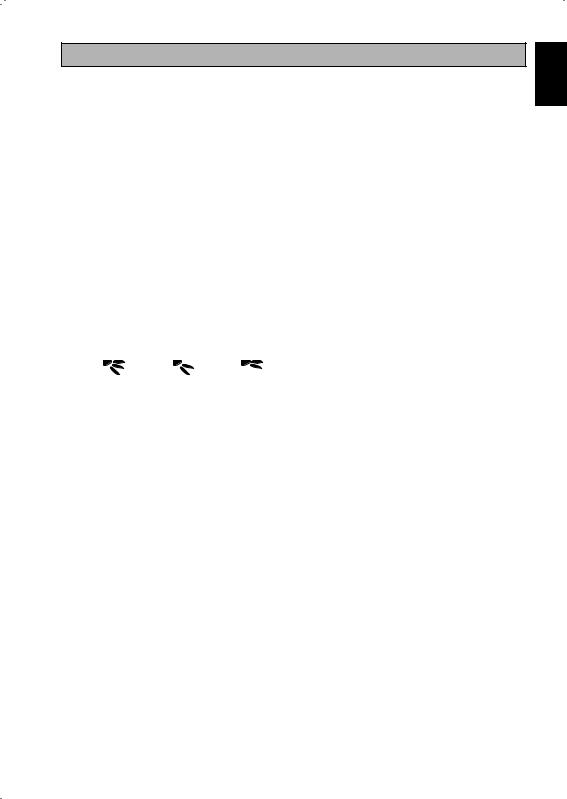
3.2Step-by-step guide
I.Open the clip on the top of the controller first follow by the bottom clip. Remove the top case of the controller from the bottom case.
II.Fix the bottom case to the wall with the 2 screw provided. Then insert the connection wire through the slot on the upper center case as shown.
III. Insert back the bottom clip first then snap the upper part shut.
Connection
wires
LCD Remote
(Top case)
MODE |
|
|
TURBO |
|
SWING |
D |
|
ELAY |
|
T |
T |
IMER |
|
|
IMER |
|
TIMER |
QUIET
 FAN
FAN
SLEEP
ON / OFF
2 x Wooden
screw LCD Remote (Bottom case)
6
MEMO

BRC51A61/62 Indication De Contríleur
3
2
1
10
9
11
8
|
AUTO |
MON TUE WED THU FRI SAT SUN ALL |
||||
|
OVERRIDE |
12 |
|
|||
|
|
|
||||
|
|
|
12 |
12 |
|
|
DRY |
AUTO |
COOL |
HEAT |
FAN |
|
|
|
|
|
|
|
SET |
|
TURBO |
QUIET |
|
SWING |
SLEEP |
TEMP. |
|
MODE
|
TURBO |
SWING |
QUIET |
DELAY |
TIMER |
TIMER |
|
TIMER |
ON |
OFF |
SLEEP |
FAN |
ON / OFF |
4
5
6
7
12
13
NO |
TOUCHE |
FONCTION |
1. |
MODE |
Sélectionnez la commande des modes de fonctionnement |
|
|
(Cool (Froid) / Heat (Chauffage) / Auto / Dry (Sec) / |
|
|
Fan (Ventilation) |
2. |
TURBO |
Activez/désactivez la fonction Turbo |
3. |
SWING |
Activez/désactivez la commande d’oscillation |
|
|
Maintenir la touche enfoncée pour changer de mode d’oscillation |
4. |
QUIET |
Activez/désactivez la fonction Silence |
5. |
SET TEMP UP |
Augmentez la température réglée en °C ou en °F |
6. |
SET TEMP DOWN |
Réduisez la température réglée en °C ou en °F |
7. |
SLEEP |
Activez/désactivez la fonction Sommeil |
8. |
OFF TIMER |
Activez/désactivez le mode de réglage MINUTERIE DE MISE EN |
|
|
ARRÊT, événements 1 et 2 |
9. |
ON TIMER |
Activez/désactivez le mode de réglage MINUTERIE DE MISE EN |
|
|
MARCHE, événements 1 et 2 |
10. |
DELAY TIMER |
Activer/désactiver la programmation de mise en marche/arrêt |
11. |
FAN |
Sélectionnez la commande des vitesses du ventilateur |
|
|
(Auto / High (Rapide)/ Med (Moyen)/ Low (Lent)) |
12. |
ON/OFF |
Appuyez sur la touche On/Off de l’unité pour annuler tous les |
|
|
réglage de la minuterie |
13. |
MODE DE RÉGLAGE DE |
Activez/désactivez le mode de réglage de l’horloge temps réel |
|
L’HORLOGE TEMPS RÉEL (HTR) |
(HTR) |
REMARQUE :
Les fonctions turbo et silence ne sont disponibles que sur les modèles sélectionnés.
i
INSTRUCTIONS D’UTILISATION
1.1Bouton de MODE
Appuyez sur le bouton MODE pour alterner entre COOL (FROID), HEAT* (CHAUD), AUTO*, DRY* (SEC), FAN (VENTILATION). Vérifiez l’affichage pour voir sur quel mode est réglée l’unité. Les fonctions *HEAT (CHAUD), AUTO et DRY (SEC) ne sont disponibles que pour les modèles sélectionnés.
1.2Vitesse de ventilation TURBO
Appuyez sur la touche TURBO une fois pour activer la vitesse de ventilation TURBO. Le symbole du turbo s’affiche. Pour désactiver la vitesse de ventilation Turbo et revenir à la vitesse de ventilation précédente, appuyez à nouveau sur la touche Turbo. Si l’utilisateur appuie sur la touche FAN (VENTILATEUR) ou QUIET (SILENCE) ou s’il éteint l’unité, la vitesse turbo est désactivée. Cette vitesse n’est valable qu’en modes COOL (FROID) et HEAT (CHAUD) pour les modèles sélectionnés.
1.3Oscillation automatique de la ventilation
•Appuyez sur le bouton SWING  pour activer la fonction d’oscillation automatique de la ventilation.
•Pour orienter la ventilation dans une direction précise, appuyez sur le bouton SWING  , attendez ensuite que le volet de ventilation souffle dans la direction désirée puis appuyez de nouveau sur le bouton.
Méthode de sélection du mode Swing (dépendant du modèle)
•Appuyez sur le bouton SWING ( ) pendant 4 secondes pour entrer dans le mode de réglage du champ. En mode de réglage local, seul le mode d’oscillation SWING MODE (
 ) est affiché.
•Appuyez sur le bouton de température  et
et  pour sélectionner la rotation du SWING MODE (
 ) depuis le Mode Swing 1 au Mode Swing 3.
•Les 3 différents modes d’oscillation (SWING MODE) suivants sont disponibles :
Mode d’oscillation 1 Mode d’oscillation 2 Mode d’oscillation 3
Le mode d’oscillation (SWING MODE) ne sera pas activé, sauf si la fonction d’oscillation (SWING) est activée.
L’oscillation est indiquée par le logo : 
•Si aucun mode ne change dans les 4 secondes, l’appareil fonctionnera selon le SWING MODE ( ) sélectionné.
1.4Vitesse de ventilation QUIET (SILENCE)
Appuyez sur la touche QUIET (SILENCE) une fois pour activer la vitesse de ventilation silence. Le symbole QUIET (SILENCE) s’affiche. Pour désactiver la vitesse de ventilation Silence et revenir à la vitesse de ventilation précédente, appuyez à nouveau sur la touche QUIET (SILENCE). Si l’utilisateur appuie sur la touche FAN (VENTILATEUR) ou TURBO ou s’il éteint l’unité, la vitesse silence est désactivée. Cette vitesse n’est valable qu’en modes COOL (FROID) et HEAT (CHAUD) pour les modèles sélectionnés.
1.5Le Bouton du Réglage de la Température «  » ou «
  »
»
Appuyez sur la touche de la température et programmez la température de votre choix en appuyant une fois sur «  » ou «
  », la température change par incréments de 1°C ou 1°F. La plage de températures par défaut s’étend de 16°C à 30°C (60°F à 86°F). Lorsque l’option 20 – 30°C est définie, la limite de la plage de température est définie entre 20°C et 30°C (68°F à 86°F). Appuyez simultanément sur les deux touches pour afficher les températures en °C ou en °F. Aucun réglage de température n’est autorisé en mode FAN (VENTILATEUR) (Aucun affichage de température réglée). L’espace est insuffisant pour afficher la température.
1.6FONCTION SLEEP (SOMMEIL)
Appuyez sur la touche SLEEP (SOMMEIL) pour activer le mode de nuit. La fonction SLEEP (SOMMEIL) n’est pas disponible en mode DRY (SEC) ni en mode FAN (VENTILATEUR).
1.7« ON TIMER » ou « OFF TIMER »
L’unité est dotée de 2 minuteries d’événements, à savoir Minuterie 1 et Minuterie 2, chacune offrant une minuterie de mise en marche (ON TIMER) et une de mise en arrêt (OFF TIMER). L’action des touches TIMER ON (MINUTERIE DE MISE EN MARCHE) et TIMER OFF (MINUTERIE DE MISE EN ARRET) est illustrée dans le Tableau 1,1.
<![endif]>Traduction des instructions d’origine FRANÇAIS
1

Tableau 1,1 : Action des touches de minuterie TIMER ON (MINUTERIE DE MISE EN MARCHE) et de TIMER OFF (MINUTERIE DE MISE EN ARRET) et séquence d’événements.
TOUCHE TIMER ON |
TOUCHE TIMER OFF |
||
Minuterie 1 ON |
Minuterie 2 ON |
Minuterie 1 OFF |
Minuterie 2 OFF |
Désactivée |
Désactivée |
Désactivée |
Désactivée |
Activée |
Désactivée |
Activée |
Désactivée |
Désactivée |
Activée |
Désactivée |
Activée |
Activée |
Activée |
Activée |
Activée |
Toutes les minuteries sont des minuteries déclenchées par des événements et peuvent être annulées par la touche ON/OFF et la fonction prioritaire.
Fixez les minuteries des événements 1 et 2
Le procédé est le même pour TIMER ON (MINUTERIE DE MISE EN MARCHE) et TIMER OFF (MINUTERIE DE MISE EN ARRET).
1.Maintenez la touche TIMER ON/OFF (MINUTERIE DE MISE EN MARCHE/ARRET) pendant 3 secondes pour entrer en mode de réglage de la minuterie.
(L’icône ON 1 ou OFF 1 clignote)
2.Appuyez sur UP (HAUT) ou DOWN (BAS) pour sélectionner Minuterie 1 ou Minuterie 2 et faire le réglage.
(Le « 1 » clignotant indique que la Minuterie 1 est actuellement sélectionnée, le « 2 » clignotant indique que la Minuterie 2 est actuellement sélectionnée)
3.Appuyez à nouveau sur la touche TIMER ON/OFF (MINUTERIE DE MISE EN MARCHE/ARRET) pour confirmer. (Le jour clignote ensuite)
4.Appuyez sur UP (HAUT) ou sur DOWN (BAS) pour sélectionner le jour.
5.Appuyez à nouveau sur la touche TIMER ON/OFF (MINUTERIE DE MISE EN MARCHE/ARRET) pour confirmer le jour. (L’heure clignote ensuite)
6.Appuyez sur UP (HAUT) ou sur DOWN (BAS) pour changer l’heure.
7.Appuyez à nouveau sur la touche TIMER ON/OFF (MINUTERIE DE MISE EN MARCHE/ARRET) pour confirmer l’heure. (Les minutes clignotent ensuite)
8.Appuyez sur UP (HAUT) ou sur DOWN (BAS) pour changer les minutes.
9.Appuyez à nouveau sur la touche TIMER ON/OFF (MINUTERIE DE MISE EN MARCHE/ARRET) pour confirmer les minutes.
Chaque minuterie (Minuterie 1 ON (MARCHE) ou Minuterie 1 OFF (ARRET) ou Minuterie 2 ON (MARCHE) ou Minuterie 2 OFF (ARRET)) ne sera réglée séparément qu’après les 7 étapes, si aucune touche n’est actionnée pendant 5 secondes au cours du réglage de la minuterie, le mode de réglage sera automatiquement désactivé et aucune modification ne sera effectuée.
Le TIMER ON/OFF (MINUTERIE DE MISE EN MARCHE/ARRET) sera vérifié toutes les 1 minute.
Il est déconseillé de régler le ON TIMER (MINUTERIE DE MISE EN MARCHE) et le OFF TIMER (MINUTERIE DE MISE EN ARRET) sur les mêmes valeurs. Si cela se produit, la minuterie effective sera traitée en priorité, comme indiqué dans le Tableau 1,2.
Exemple :
Réglages ON TMR 2 (MINUTERIE DE MISE EN MARCHE 2) : DAY – TUE, TIMER – 5.00pm Réglages OFF TMR 1 (MINUTERIE DE MISE EN ARRET 1) : DAY – TUE, TIMER – 5.00pm Résultat lorsque l’HTR atteint 17h00 le TUE (MAR) :
–si l’unité est en marche, aucune réaction.
–si l’unité est à l’arrêt, elle se met en marche.
Tableau 1,2 : Priorité de minuterie
Priorité |
Minuterie |
|
1 |
(La plus élevée) |
ONTMR2 |
2 |
|
OFFTMR2 |
3 |
|
ONTMR1 |
4 |
(La plus faible) |
OFFTMR1 |
Sur réception de rayons IR, la télécommande sans fil IR prend la priorité sur les réglages ON TIMER 2 (MINUTERIE DE MISE EN MARCHE 2) et OFF TIMER 2 (MINUTERIE DE MISE EN ARRET 2).
2

1.8Fonction DELAY TIMER
Appuyez sur la touche DELAY TIMER une fois pour activer la fonction de programmation de mise en marche/arrêt pendant 1 heure. Un indicateur « OVERRIDE » s’affiche sur l’écran LCD. Appuyez de nouveau sur la même touche pour augmenter le réglage à 2 heures. Un indicateur « OVERRIDE » s’allumera. Appuyer de nouveau désactivera la fonction de programmation de mise en marche/arrêt. Une fois la programmation de mise en marche/arrêt terminée, la fonction de programmation de mise en marche/arrêt est désactivée et le logo disparaît. Toutes les autres minuteries seront reprises.
1.9Fonction de vitesse FAN (VENTILATEUR)
La vitesse de ventilation peut être changée en appuyant sur la touche FAN (VENTILATEUR) :
Lent > Moyen > Rapide > Auto >
*La vitesse FAN (VENTILATEUR) n’est pas disponible en mode DRY (SEC).
1.10Bouton ON/OFF (MARCHE’/ARRÊT)
Mise en marche :
–Appuyez sur la touche ON/OFF (MARCHE/ARRET), l’écran LCD s’affiche intégralement et l’unité est mise en marche.
Mise en arrêt :
–Appuyez sur la touche ON/OFF (MARCHE/ARRET), l’écran LCD affiche l’horloge temps réel et l’unité est mise à l’arrêt.
1.11Réglages de mise sous tension
L’unité démarre en conservant le dernier réglage de la carte principale pendant la mise sous tension. Si les dernières informations ne sont pas disponibles, l’unité utilisera les réglages par défaut. Les réglages par défaut sont les suivants :
Unité : |
Arrêt |
Mode : |
Refroidissement |
Vitesse du ventilateur : |
Élevé |
RTC: |
12:00AM, MONDAY |
Oscillation : |
Arrêt |
Mode d’oscillation : |
Standard |
Minuteries : |
Désactiver |
Turbo : |
Désactiver |
Silence : |
Arrêt |
Mise en sommeil : |
Arrêt |
Prioritaire : |
Désactiver |
1.12Affichage de l’horloge temps réel (HTR)
L’HTR est affichée à l’écran lorsque l’unité et en marche ou à l’arrêt, sauf en cas de panne d’électricité ou de code d’erreur.
Définir le réglage de l’HTR
1.Pressez la touche HTR une fois pour activer le mode de réglage HTR. (Le jour clignote)
2.Appuyez sur UP (HAUT) ou sur DOWN (BAS) pour sélectionner le jour.
3.Appuyez à nouveau sur HTR pour confirmer le jour. (L’heure clignote ensuite)
4.Appuyez sur UP (HAUT) ou sur DOWN (BAS) pour changer l’heure.
5.Appuyez à nouveau sur HTR pour confirmer l’heure. (Les minutes clignotent ensuite)
6.Appuyez sur UP (HAUT) ou sur DOWN (BAS) pour changer les minutes.
7.Appuyez à nouveau sur HTR pour confirmer les minutes.
L’HTR ne sera réglée séparément qu’après les 7 étapes, si aucune touche n’est actionnée pendant 5 secondes au cours du réglage de la minuterie, le mode de réglage sera automatiquement désactivé et aucune modification ne sera effectuée.
1.13Verrouillage de touches
La fonction de verrouillage de touches sert à empêcher tout changement de réglage. Maintenez les touches TURBO et QUIET (SILENCE) enfoncées pendant 5 secondes pour activer/désactiver la fonction de verrouillage de touches : « KEYLOCK » (VERROUILLAGE DE TOUCHE) s’affiche/disparaît de l’écran LCD. Dès que la totalité des touches est verrouillée, seules les touches ON/OFF (MARCHE/ARRET), TURBO et QUIET (SILENCE) (pour déverrouiller) peuvent être pressées.
<![endif]>FRANÇAIS
3

1.14Batterie de secours
La batterie de secours sert à conserver l’HTR et les réglages de minuterie programmable sur 7 jours quand l’alimentation est coupée, pendant au minimum 1 mois d’affilée pour chaque nouveau jeu de piles installées. Pour les unités sans batterie de secours, le réglage par défaut est de 12:00 le lundi, et la minuterie est effacée au démarrage.
1.15Indicateur d'erreur
Si une condition anormale est détectée, un code d’erreur s’affiche. Le code d’erreur s’affiche à la place des segments de l’HTR (clignotants), ce qui signifie que dès qu’une erreur survient, l’HTR ne s’affiche pas en plus du code d’erreur. Le format du code d’erreur sera le suivant :
Code d’erreur DX
|
Description d’erreur |
|
|
Capteur intérieur ouvert ou faible |
|
E1 |
|
Capteur à bobine intérieur ouvert |
|
E2 |
|
Capteur à bobine extérieur ouvert |
|
E3 |
|
Surcharge du compresseur/Capteur à bobine intérieur faible/Capteur à bobine |
|
E4 |
|
extérieur faible |
|
||
|
|
||
Charge de fluide frigorigène à faible/Fuite de gaz/Extérieur anormale |
|
E5 |
|
Erreur de pompe à eau |
|
E6 |
|
Capteur à bobine extérieur existant (modèle MS) |
|
E7 |
|
Erreur matérielle (Broche de commutation discrète faible) |
|
E8 |
|
Erreur de retour du ventilateur de l’unité intérieure |
|
E9 |
|
Erreur EEPROM |
|
EE |
|
Code d’erreur CW |
|
||
|
|
|
|
|
Description d’erreur |
|
|
Capteur intérieur ouvert ou faible |
|
E1 |
|
Capteur de la conduite d’eau ouvert ou en court-circuit |
|
E2 |
|
Température de la conduite d'eau faible |
|
E4 |
|
Température de la conduite d'eau mauvaise/erronée |
|
E5 |
|
Erreur de la pompe à eau |
|
E6 |
|
Erreur matérielle (Broche de commutation discrète faible) |
|
E8 |
|
Erreur de retour du ventilateur de l’unité intérieure |
|
E9 |
|
Fau daignostics (pour modèle à inverseur seulement) |
|
||
S’il y a une anomalie détectée, le contrôleur câblé SLM9 va clignoter le code d’erreur |
|
||
|
|
|
|
CODE |
SIGNIFICATION |
|
|
D’ERREUR |
|
||
|
|
|
|
|
|
|
|
00 |
NORMAL |
|
|
A1 |
ERREUR PCB DANS LA SECTION INTÉRIEURE |
|
|
A3 |
ANOMALIE DE LA POMPE DE VIDANGE |
|
|
A5 |
ANTIGEL (REFROIDISSEMENT) / ÉCHANGEUR DE CHALEUR DE |
|
|
SURCHAUFFE(CHAUFFAGE) |
|
||
|
|
||
A6 |
ANOMALIE SUR LE VENTILATEUR D’INTÉRIEUR |
|
|
AH |
ANOMALIE DU FILTRE À AIR ÉLECTRIQUE |
|
|
C4 |
THERMISTOR DE L'ÉCHANGEUR THERMIQUE INTÉRIEUR (1) EN COURT-CIRCUIT/OUVERT |
||
C5 |
THERMISTOR DE L'ÉCHANGEUR THERMIQUE INTÉRIEUR (2) EN COURT-CIRCUIT/OUVERT |
||
C7 |
ERREUR DE L’INTERRUPTEUR DE LIMITE D’AILETTE |
|
|
C9 |
COURT-CIRCUIT/OUVERTURE DANS LE THERMISTOR DE PIÈCE INTÉRIEURE |
|
|
4

CODE |
SIGNIFICATION |
|
|
D’ERREUR |
|
|
|
|
|
|
|
|
|
|
|
E1 |
ERREUR DE CARTE EXTÉRIEURE |
|
|
E3 |
PROTECTION HAUTE PRESSION |
|
|
E4 |
PROTECTION BASSE PRESSION |
|
|
|
|||
E5 |
VERROU DU MOTEUR DU COMPRESSEUR /COMPRESSEUR SURCHARGÉ |
|
<![if ! IE]> <![endif]>FRANÇAIS |
E6 |
ERREUR DE DÉMARRAGE DU COMPRESSEUR |
|
|
|
|
||
E7 |
VERROU DU MOTEUR DE VENTILATEUR CC EXTÉRIEUR |
|
|
E8 |
SURINTENSITÉ D’ENTRÉE CA |
|
|
|
|
|
|
E9 |
ERREUR EXV |
|
|
EA |
ERREUR DE VANNE À 4 VOIES |
|
|
F3 |
TUYAUTERIE DE VIDANGE DE SURCHAUFFE |
|
|
F6 |
ÉCHANGEUR DE CHALEUR DE SURCHAUFFE |
|
|
HO |
ERREUR DU SYSTÈME DE CAPTEUR DU COMPRESSEUR |
|
|
H3 |
ERREUR DE L’INTERRUPTEUR HAUTE PRESSION |
|
|
H6 |
ERREUR DE DÉTECTION DE L’ALIMENTATION DU COMPRESSEUR |
|
|
H7 |
SURCHARGE/SURINTENSITÉ DU MOTEUR DU VENTILATEUR/ANOMALIE DU CAPTEUR |
|
|
H8 |
ERREUR DU CAPTEUR DE COURANT CA |
|
|
H9 |
THERMISTANCE À AIR EXTÉRIEUR EN COURT-CIRCUIT/OUVERT |
|
|
J1 |
ERREUR DU CAPTEUR DE PRESSION |
|
|
J3 |
THERMISTANCE DE LA TUYAUTERIE DE VIDANGE DU COMPRESSEUR EN COURT-CIRCUIT/ |
|
|
OUVERTE/ MAL POSITIONNÉE |
|
|
|
|
|
|
|
J5 |
COURT-CIRCUIT/OUVERTURE DANS LE THERMISTOR DU TUYAU D’ASPIRATION |
|
|
J6 |
THERMISTANCE D’ÉCHANGEUR DE CHALEUR EXTÉRIEUR EN COURT-CIRCUIT/OUVERT |
|
|
J7 |
COURT-CIRCUIT/OUVERTURE DANS LE THERMISTOR DE L’ÉCHANGEUR THERMIQUE DE |
|
|
SOUSREFROIDISSEMENT |
|
|
|
|
|
|
|
J8 |
THERMISTANCE DE LA TUYAUTERIE DU LIQUIDE EN COURT-CIRCUIT/OUVERTE |
|
|
J9 |
THERMISTANCE DE LA TUYAUTERIE DE GAZ EN COURT-CIRCUIT/OUVERTE |
|
|
L1 |
ERREUR PCB EXTÉRIEURE DE L’INVERSEUR |
|
|
L3 |
BOÎTIER DE COMMANDE EXTÉRIEUR DE SURCHAUFFE |
|
|
L4 |
DISSIPATEUR THERMIQUE DE SURCHAUFFE |
|
|
L5 |
ERREUR IPM /ERREUR IGBT |
|
|
L8 |
SURINTENSITÉ DU COMPRESSEUR DE L’INVERSEUR |
|
|
L9 |
PRÉVENTION DE SURINTENSITÉ DU COMPRESSEUR |
|
|
LC |
ERREUR DE COMMUNICATION (PCB DE LA COMMANDE EXTÉRIEURE ET PCB DE L’INVERSEUR) |
|
|
P1 |
PHASE OUVERTE OU DÉSÉQUILIBRE DE TENSION |
|
|
P4 |
THERMISTANCE DE DISSIPATEUR DE CHALEUR EN COURT-CIRCUIT/OUVERT |
|
|
PJ |
ERREUR DE RÉGLAGE DE LA CAPACITÉ |
|
|
U0 |
INSUFFISANCE DE GAZ |
|
|
U2 |
TENSION CC HORS PLAGE |
|
|
U4 |
ERREUR DE COMMUNICATION |
|
|
U7 |
ERREUR DE COMMUNICATION (CARTE DE COMMANDE ET CARTE IPM) |
|
|
UA |
ERREUR D’INSTALLATION |
|
|
UF |
MAUVAISE CORRESPONDANCE DANS L’INSTALLATION DU CÂBLAGE ET DE LATUYAUTERIE/ |
|
|
MAUVAIS CÂBLAGE/INSUFFISANCE EN GAZ |
|
|
|
|
|
|
|
UH |
ANTIGEL (AUTRES PIÈCES) |
|
|
5
2.0RÉGLAGE MATÉRIEL
L’unité bénéficie de 2 fonctions de cavaliers pour contrôler le fonctionnement du tableau. Tableau 2,0 : Récapitulatif des réglages matériels
OPTION |
Avec cavalier |
Sans cavalier |
|
|
|
|
|
Régler plage de |
Régler plage de temp. de 20°C à 30°C |
Régler plage de temp. de 16°C à 30°C |
|
temp. |
(Valeur par défaut) |
||
|
|||
|
|
|
|
|
Désactiver le turbo et la vitesse de |
Activer le turbo et la vitesse de |
|
TURBO_QUIET |
ventilation silence |
||
ventilation silence |
|||
|
(Valeur par défaut) |
||
|
|
||
|
|
|
*Seulement applicable au modèle avec fonctions Turbo ou Silence intégrées.
3.0INSTALLATION
3.1Accessoires
Les accessoires suivants sont compris avec ce manuel. S’il manque des éléments, veuillez contacter votre concessionnaire immédiatement.
1. Télécommande
2. Vis à bois (2 vis) & Vis de l’unité (2 vis) 3. Manuel d’utilisation
4. Pile
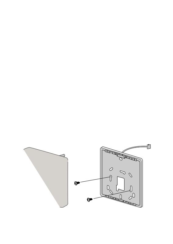
3.2Guide Détaillé
I.Ouvrez d’abord l’attache du dessus du contrôleur puis l’attache du bas. Retirez l’enveloppe supérieure du contrôleur de l’enveloppe inférieure.
II.Fixez l’enveloppe inférieure sur le mur avec les 2 vis fournies. Insérez ensuite le fil de connexion à travers la fente sur la partie centrale supérieure de l’enveloppe, comme dans l’illustration.
III. Réinsérez d’abord l’attache du bas puis clipsez la partie supérieure pour fermer.
Fils de raccordement
Télécommande LCD (boîtier supérieur)
MODE |
|
|
TURBO |
|
SWING |
D |
|
ELAY |
|
T |
T |
IMER |
|
|
IMER |
|
TIMER |
QUIET
 FAN
FAN
SLEEP
ON / OFF
2 x Vis à bois
Télécommande LCD (Boîtier inférieure)
6

LE MÉMO

BRC51A61/62 Controller-Anzeige
3
2
1
10
9
11
8
|
AUTO |
MON TUE WED THU FRI SAT SUN ALL |
||||
|
OVERRIDE |
12 |
|
|||
|
|
|
||||
|
|
|
12 |
12 |
|
|
DRY |
AUTO |
COOL |
HEAT |
FAN |
|
|
|
|
|
|
|
SET |
|
TURBO |
QUIET |
|
SWING |
SLEEP |
TEMP. |
|
MODE
|
TURBO |
SWING |
QUIET |
DELAY |
TIMER |
TIMER |
|
TIMER |
ON |
OFF |
SLEEP |
FAN |
ON / OFF |
4
5
6
7
12
13
NO |
TASTE |
FUNKTION |
|
|
|
1. |
MODE |
Auswahl der Steuerung für Betriebsmodi (Cool (Kühlen) / |
|
|
Heat (Heizen) / Auto (Auto) / Dry (Trocknen) / Fan (Ventilator)) |
2. |
TURBO |
Aktivierung/Deaktivierung der Turbo-Funktion |
3. |
SWING |
Pendelsteuerung aktivieren/deaktivieren |
|
|
Taste halten zur Änderung des Swing-Modus |
4. |
QUIET |
Aktivierung/Deaktivierung der Ruhefunktion |
5. |
SET TEMP UP |
Eingestellte Temperatur in °C oder °F erhöhen |
6. |
SET TEMP DOWN |
Eingestellte Temperatur in °C oder °F erhöhen |
7. |
SLEEP |
Aktivierung/Deaktivierung der Schlaffunktion |
8. |
OFF TIMER |
Einschalten/Ausschalten der OFF TIMER-Einstellungsmodus von Ereignis |
|
|
1 und 2 |
9. |
ON TIMER |
Einschalten/Ausschalten der ON TIMER-Einstellungsmodus von Ereignis |
|
|
1 und 2 |
|
|
|
10. |
DELAY TIMER |
Timer aktivieren/deaktivieren |
|
|
|
11. |
FAN |
Auswahl der Steuerung für Ventilatorgeschwindigkeiten |
|
|
(Auto (Auto)/ High (Hoch)/ Med (Mittel)/ Low (Niedrig)) |
|
|
|
12. |
ON/OFF |
An/Aus des Geräts mit Löschung aller Timer-Funktionen |
|
|
|
13. |
REELLE ZEITUHR (RTC) |
Einschalten/Ausschalten des Einstellungsmodus der reellen Zeituhr (RTC) |
|
|
|
HINWEIS:
Turbound Ruhefunktion sind nur bei ausgewählten Modellen verfügbar.
i
BEDIENUNGSANLEITUNG
1.1MODE-Taste (MODUS)
Die MODE-Taste betätigen, um den Betrieb von COOL (KÜHL), HEAT* (WARM), AUTO* (AUTO), DRY* (TROCKEN) oder FAN (GEBLÄSE) umzuschalten. Sehen Sie auf dem Display nach, in welchem Modus sich die Steuerung befindet. *HEAT (WARM), AUTO (AUTO) und DRY (TROCKEN) sind nur für ausgewählte Modelle verfügbar.
1.2TURBO Ventilatorgeschwindigkeit
Drücken Sie einmal die TURBO-Taste, um die Turbo-Gebläsedrehzahl zu aktivieren. Das Turbo-Symbol wird angezeigt. Um die Turbo-Gebläsedrehzahl zu deaktivieren und wieder zur vorherigen Gebläsedrehzahl zurückzukehren, drücken Sie erneut einmal die Turbo-Taste. Wenn der Benutzer die FAN-Taste oder die QUIET-Taste drückt oder das Gerät ausschaltet, wird die Turbo-Geschwindigkeit deaktiviert. Diese Geschwindigkeit ist nur bei ausgewählten Modellen im COOL-(Kühl-) und HEAT-(Heiz-)Modus verfügbar.
1.3Automatische Luftschwingung
•Durch Betätigen des SWING  Knopfs wird die automatische Luftschwingungsfunktion aktiviert.
•Damit die Luft in eine bestimmte Richtung bläst, wird der SWING  Knopf betätigt, danach warten, bis sich
die Lüftungsschlitze in die gewünschte Richtung bewegen und dann den Knopf nochmals betätigen.
Auswahlverfahren für Swing-Modus (von Model abhängig)
•Drücken Sie die Taste SWING ( ) für 4 Sekunden lang, um in das Feld des Einstellmodus zu gelangen. Im Feldeinstellungsmodus erscheint nur die Meldung SWING MODE (
 ).
).
•Drücken Sie die Temperaturtaste und
und um die Drehzahl von SWING MODE (
 ) von Swing-Modus 1 bis auf Swing-Modus 3 auszuwählen.
•Folgende drei automatische Luftschwenkmodi (SWING MODE)stehen zur Verfügung:
Luftschwenkmodus 1 |
Luftschwenkmodus 2 |
Luftschwenkmodus 3 |
SWING MODE wird erst aktiviert, wenn SWING eingeschaltet ist.
Der Schwenkmodus wird durch dieses Logo angezeigt: 
•Falls sich keiner Modus innerhalb 4 Sekunden ändert, funktioniert das Gerät gemäß den ausgewählten
SWING MODE( ).
).
1.4QUIET Ventilatorgeschwindigkeit
Drücken Sie einmal die QUIET-Taste, um die Ruhe-Gebläsedrehzahl zu aktivieren. Das QUIET-Symbol wird angezeigt. Um die Ruhe-Gebläsedrehzahl zu deaktivieren und wieder zur vorherigen Gebläsedrehzahl zurückzukehren, drücken Sie erneut einmal die QUIET-Taste. Wenn der Benutzer die FAN-Taste oder die TURBO-Taste drückt oder das Gerät ausschaltet, wird die Ruhe-Geschwindigkeit deaktiviert. Diese Geschwindigkeit ist nur bei ausgewählten Modellen im COOL-(Kühl-) und HEAT-(Heiz-)Modus verfügbar.
1.5„ “ oder „
 “ Temperatur-Einstell-Taste
Betätigen Sie die Temperaturtaste und stellen Sie die gewünschte Temperatur ein. Drücken Sie dazu einmal
die Taste „ “ oder „
 “. Die Temperatur ändert sich um 1 °C oder 1 °F. Der standardmäßig einstellbare Temperaturbereich liegt zwischen 16 °C und 30 °C (60 °F und 86 °F). Wenn die Option 20 - 30 ºC eingestellt ist, wird die Temperaturbereichsgrenze auf 20 ºC bis 30 ºC (68 °F bis 86 °F) eingestellt. Durch gleichzeitiges Drücken beider Knöpfe wird die Temperatureinstellung zwischen Grad Celsius und Grad Fahrenheit umgeschaltet. Im FAN-Modus ist keine Temperatureinstellung zulässig (keine Einstellung der Temperaturanzeige). Es gibt keine Anzeige der Zimmertemperatur.
1.6SLEEP Funktion
Drücken Sie die SLEEP-Taste, um die Schlummerfunktion zu aktivieren. Die SLEEP-Funktion ist im DRYund im FAN-Modus nicht verfügbar.
1.7„ON TIMER“ und „OFF TIMER“
Das Gerät hat 2 Ereignistimer, und zwar Timer 1 und Timer 2. Jedes Ereignis hat jeweils einen ON-TIMER und einen OFF-TIMER. Die Tastendruckfunktionen für Timer ON und Timer OFF werden in Tabelle 1,1 angezeigt.
<![endif]>Übersetzung der Original-Anleitungen DEUTSCH
1

Tabelle 1,1 : Tastendruckund Ereignissequenz für Timer ON und Timer OFF.
TIMER ON KEY (TIMER EIN-TASTE) |
TIMER OFF KEY (TIMER AUS-TASTE) |
||
|
|
|
|
ON Timer 1 |
ON Timer 2 |
OFF Timer 1 |
OFF Timer 2 |
|
|
|
|
Deaktivieren |
Deaktivieren |
Deaktivieren |
Deaktivieren |
Aktivieren |
Deaktivieren |
Aktivieren |
Deaktivieren |
|
|
|
|
Deaktivieren |
Aktivieren |
Deaktivieren |
Aktivieren |
|
|
|
|
Aktivieren |
Aktivieren |
Aktivieren |
Aktivieren |
Alle Timer sind durch Ereignisse ausgelöste Timer und können durch die ON/OFF-Taste und die OverrideFunktion deaktiviert werden.
Stellen Sie die Timer für Ereignis 1 und Ereignis 2 ein
Der Prozess für Timer ON und Timer OFF ist gleich.
1.Halten Sie die Taste Timer ON/OFF 3 Sekunden lang gedrückt, um in den Timer-Einstellungsmodus zu wechseln.
(Das Symbol ON 1 oder OFF 1 blinkt)
2.Drücken Sie UP oder DOWN, um zur Einstellung Timer 1 oder Timer 2 zu wählen.
(Wenn „1“ blinkt, bedeutet dies, dass momentan Timer 1 ausgewählt ist. Wenn „2“ blinkt, gibt dies an, dass derzeit Timer 2 ausgewählt ist)
3.Drücken Sie zur Bestätigung erneut die Taste Timer ON/OFF. (Als nächstes blinkt der Tag)
4.Drücken Sie UP oder DOWN, um den Tag auszuwählen.
5.Drücken Sie zur Bestätigung des Tags erneut die Taste Timer ON/OFF. (Als nächstes blinkt die Stunde)
6.Drücken Sie UP oder DOWN, um die Stunde zu ändern.
7.Drücken Sie zur Bestätigung der Stunde erneut die Taste Timer ON/OFF. (Als nächstes blinken die Minuten)
8.Drücken Sie UP oder DOWN, um die Minute zu ändern.
9.Drücken Sie zur Bestätigung der Minute erneut die Taste Timer ON/OFF.
Die einzelnen Timer (Timer 1 ON oder Timer 1 OFF oder Timer 2 ON oder Timer 2 OFF) können nur separat nach Durchlaufen sämtlicher 7 Schritte eingestellt werden. Falls während der Timer-Einstellung 5 Sekunden lang keine Tasteneingabe erfolgt, wird der Einstellungsmodus automatisch beendet, und es werden keine Änderungen vorgenommen.
Der ON/OFF-Timer wird jeweils nach 1 Minute überprüft.
Es wird nicht empfohlen, ON TIMER und OFF TIMER auf die gleichen Werte zu setzen. Sollte dies dennoch auftreten, wird der wirksame Timer mit Priorität behandelt (siehe Tabelle 1,2).
Beispiel:
ON TMR 2-Einstellungen: DAY (Tag) – TUE (Di), TIMER – 5.00pm (17 Uhr) OFF TMR 1-Einstellungen: DAY (Tag) – TUE (Di), TIMER – 5.00pm (17 Uhr) Ergebnis, wenn die RTC 5.00 pm (17 Uhr) am TUE (Di) erreicht:
–wenn das Gerät eingeschaltet ist, keine Reaktion.
–wenn das Gerät ausgeschaltet ist, wird es eingeschaltet.
Tabelle 1,2 : Timer-Priorität
Priorität |
Timer (Zeiteinstellung) |
|
|
|
|
1 |
(am höchsten) |
ONTMR2 |
|
|
|
2 |
|
OFFTMR2 |
3 |
|
ONTMR1 |
4 |
(am niedrigsten) |
OFFTMR1 |
|
|
|
Bei IR-Empfang löscht die drahtlose IR-Fernbedienung die Einstellungen von ON TIMER 2 und OFF TIMER 2.
2
 Loading...