


 Loading...
User’s
Manual
Models MV1004/MV1006/MV1008/MV1012/MV1024
MV2008/MV2010/MV2020/MV2030/MV2040/MV2048
MV1000/MV2000
Communication Interface
IM MV1000-17E
2nd Edition

Thank you for purchasing the MV1000/MV2000 (hereafter referred to as the MV). This Communication Interface User’s Manual contains information about the Ethernet and serial interface communication functions. To ensure correct use, please read this manual thoroughly before beginning operation.
Keep this manual in a safe place for quick reference in the event a question arises. The following manuals, including this one, are provided as MV1000/MV2000 manuals. Please read all of them.
• Electronic Manuals Provided on the Accompanying CD-ROM
Manual Title |
Manual No. |
Description |
MV1000 |
IM MV1000-02E |
Explains how to set up the MV1000 for |
First Step Guide |
|
making measurements using the quick |
|
|
settings function. Connection diagrams are |
|
|
also provided to help you with the setup. |
MV2000 |
IM MV2000-02E |
Explains how to set up the MV2000 for |
First Step Guide |
|
making measurements using the quick |
|
|
settings function. Connection diagrams are |
|
|
also provided to help you with the setup. |
MV1000/MV2000 |
IM MV1000-01E |
Explains all functions except communication |
User’s Manual |
|
functions and procedures of the MV1000 and |
|
|
MV2000. |
MV1000/MV2000 |
IM MV1000-17E |
Explains the MV1000 and MV2000 Ethernet |
Communication Interface |
|
and serial interface communication functions. |
User’s Manual |
|
|
• Paper Manuals
Manual Title |
Manual No. |
Description |
MV1000 |
IM MV1000-02E |
This guide is also provided in the CD-ROM. |
First Step Guide |
|
|
MV2000 |
IM MV2000-02E |
This guide is also provided in the CD-ROM. |
First Step Guide |
|
|
MV1000/MV2000 |
IM MV1000-91C |
Provides information about pollution control. |
Control of Pollution |
|
|
Caused by the Product |
|
|
•DAQSTANDARD Manuals
All manuals other than IM 04L41B01-66EN are contained in the DAQSTANDARD CD.
Manual Title |
Manual No. |
DAQSTANDARD Viewer User's Manual |
IM 04L41B01-63EN |
DAQSTANDARD Hardware Setup User's Manual |
IM 04L41B01-64EN |
DAQSTANDARD DX100P/DX200P Hardware Configurator User's |
IM 04L41B01-65EN |
Manual |
|
Installing DAQSTANDARD |
IM 04L41B01-66EN |
Notes
•The contents of this manual are subject to change without prior notice as a result of continuing improvements to the instrument’s performance and functions. The figures given in this manual may differ from those that actually appear on your screen.
•Every effort has been made in the preparation of this manual to ensure the accuracy of its contents. However, should you have any questions or find any errors, please contact your nearest YOKOGAWA dealer.
•Copying or reproducing all or any part of the contents of this manual without YOKOGAWA’s permission is strictly prohibited.
•The TCP/IP software of this product and the document concerning the TCP/IP software have been developed/created by YOKOGAWA based on the BSD Networking Software, Release 1 that has been licensed from the Regents of the University of California.
2nd Edition : August 2010 (YK)
All Rights Reserved, Copyright © 2007 Yokogawa Electric Corporation
IM MV1000-17E

Trademarks
•MVAdvanced is a trademark of Yokogawa Electric Corporation.
•Microsoft and Windows are either registered trademarks or trademarks of Microsoft Corporation in the United States and/or other countries.
•Adobe and Acrobat are trademarks of Adobe Systems Incorporated.
•Company and product names that appear in this manual are registered trademarks or trademarks of their respective holders.
•In this manual, the ™ and ® symbols do not accompany trademarks or registered trademarks.
Revisions
• |
1st Edition: |
December 2007 |
• |
2nd Edition: |
August 2010 |
ii
IM MV1000-17E

How to Use This Manual
The following symbols are used in this manual.
Unit
•k stands for 1000. Example: 5 kg, 100 kHz
•K stands for 1024. Example: 640 KB
Markings
The following safety notations are used in this manual.
Improper handling or use can lead to injury to the user or damage to the instrument. This symbol appears on the instrument to indicate that the user must refer to the user's manual for special instructions. The same symbol appears in the corresponding place in the user’s manual to identify those instructions. In the manual, the symbol is used in conjunction with the word WARNING or CAUTION.
|
WARNING |
|
Calls attention to actions or conditions that could cause serious or |
|
|
|
fatal injury to the user, and precautions that can be taken to prevent |
|
|
|
such occurrences. |
|
|
|
Calls attentions to actions or conditions that could cause light |
|
CAUTION |
|
|
|
|
|
injury to the user or damage to the instrument or user’s data, and |
|
|
|
precautions that can be taken to prevent such occurrences. |
Note
Calls attention to information that is important for proper operation of the instrument.
Bold Characters
Bold characters are used to indicate text that appears on the screen or operation keys.
The ◊ symbol indicates key and menu operations.
Procedural Explanations
This manual mainly describes the MV1000 procedures. Where procedures differ between the MV2000 and MV1000, the MV2000 procedures are also provided.
High-Speed and Medium-Speed Model Groupings
This manual uses the terms high-speed input model and medium-speed input model to distinguish between MV models as follows:
Model Type |
Model |
High-speed input model |
MV1004, MV1008, and MV2008 |
Medium-speed input model |
MV1006, MV1012, MV1024, |
|
MV2010, MV2020, MV2030, MV2040, and MV2048 |
IM MV1000-17E |
iii |

Communication Ports
Rear Panel
MV1000
Ethernet port
RS-422/RS-485 port (option)
A serial port that is provided with the /C3 option.
MV2000 |
Ethernet port
An Ethernet port that comes standard.
RS-232 port (option)
A serial port provided with the
/C2 option.
RS-422/RS-485 port (option)
A serial port that is provided with the /C3 option.
RS-232 port (option)
A serial port provided with the
/C2 option.
iv
IM MV1000-17E
Contents
How to Use This Manual.................................................................................................................. |
iii |
Communication Ports....................................................................................................................... |
iv |
Chapter 1 Overview of Communication Functions
1.1 |
Ethernet Interface................................................................................................................. |
1-1 |
1.2 |
Serial Interface..................................................................................................................... |
1-7 |
1.3 |
Modbus Protocol.................................................................................................................. |
1-8 |
Chapter 2 Using the Ethernet Interface
2.1 |
Workflow for Using the Ethernet Interface............................................................................ |
2-1 |
2.2 |
Connecting the MV............................................................................................................... |
2-2 |
2.3 |
Sending E-mail Messages.................................................................................................... |
2-8 |
2.4 |
Monitoring the MV on a PC Browser.................................................................................. |
2-17 |
2.5 |
Accessing Measured Data Files on the MV from a PC.......................................................... |
2-23 |
2.6 |
Transferring Data Files from the MV.................................................................................. |
2-25 |
2.7 |
Synchronizing the Time...................................................................................................... |
2-28 |
2.8 |
Reading/Writing the MV Data from Another Device via Modbus........................................ |
2-30 |
2.9 |
Reading/Writing Data on Another Device from the MV via Modbus................................... |
2-31 |
2.10 |
Usage Example of the Modbus Function........................................................................... |
2-40 |
Chapter 3 Using the Serial Interface
3.1 |
Workflow for Using the Serial Interface................................................................................ |
3-1 |
3.2 |
Connecting the MV............................................................................................................... |
3-2 |
3.3 |
Configuring the Serial Interface............................................................................................ |
3-8 |
3.4 |
Reading/Writing the MV Data from Another Device via Modbus.......................................... |
3-9 |
3.5 |
Reading/Writing Data on Another Device from the MV via Modbus................................... |
3-10 |
3.6 |
Usage Example of the Modbus Function........................................................................... |
3-13 |
Chapter 4 Commands
4.1 |
Command Syntax................................................................................................................. |
4-1 |
4.2 |
A List of Commands............................................................................................................. |
4-3 |
4.3 |
Setup Parameters................................................................................................................ |
4-8 |
4.4 |
Setting Commands (Setting).............................................................................................. |
4-10 |
4.5 |
Setting Commands (Control).............................................................................................. |
4-24 |
4.6 |
Basic Setting Commands................................................................................................... |
4-28 |
4.7 |
Output Commands (Control).............................................................................................. |
4-39 |
4.8 |
Output Commands (Setting/Measured/Computed Data Output)........................................ |
4-40 |
4.9 |
Output Commands (RS-422/485 Commands)................................................................... |
4-42 |
4.10 |
Output Commands (Special Response Commands)......................................................... |
4-43 |
4.11 |
Maintenance/Test Commands (available when using the maintenance/test server function |
|
|
via the Ethernet interface).................................................................................................. |
4-43 |
4.12 |
Instrument Information Output Commands (available when using the instrument information |
|
|
server function via the Ethernet interface).......................................................................... |
4-45 |
1
2
3
4
5
6
7
App
Index
IM MV1000-17E

Contents
Chapter 5 Responses |
|
|
5.1 |
Response Syntax................................................................................................................. |
5-1 |
5.2 |
Text Data Output Format...................................................................................................... |
5-6 |
5.3 |
Binary Data Output Format................................................................................................ |
5-27 |
5.4 |
Instrument Information Output Format............................................................................... |
5-32 |
Chapter 6 |
Status Reports |
|
|
|
6.1 |
Status Information and Filter................................................................................................ |
6-1 |
|
6.2 |
Status Information Bit Structure........................................................................................... |
6-2 |
Chapter 7 |
Specifications |
|
|
|
7.1 |
Ethernet Interface Specifications.......................................................................................... |
7-1 |
|
7.2 |
Serial Interface Specifications.............................................................................................. |
7-2 |
|
7.3 |
Modbus Protocol Specifications........................................................................................... |
7-3 |
Appendix
Index
vi
IM MV1000-17E

Chapter 1 Overview of Communication Functions
1.1Ethernet Interface
This chapter gives an overview of the MV Ethernet communication functions.
Modbus Communications
The MV can connect to a Modbus device and read and write to the device’s internal registers. See section 1.3 for details.
Setting/Measurement Server
•You can use this feature to set almost all of the settings that can be configured from the front panel keys. However, you cannot use this feature to turn the power ON/OFF, register users, set the key lock password, or set the connection destination of the FTP client function.
•You can use this feature to transmit the following types of data.
•Measured, computed1, and external input data2
•Files in the internal memory or files on an external storage medium
•Setup information and status byte
•Logs of operations errors, communications, etc.
•Alarm summaries and message summaries
•Relay status information
Measured, computed1, and external input2 data can be transmitted to a PC in binary or ASCII format. Other types of data are transmitted in text format. For a description of data output formats, see chapter 5.
1/M1 option.
2MV2000 with the /MC1 option.
•You can use setting mode commands (see sections 4.4 and 4.5), basic setting mode commands (see section 4.6), and output commands (see sections 4.7 and 4.8) with this feature.
•You can use this feature via an Ethernet interface or serial interface (/C2 or /C3 option).
•If you want to use this feature via a serial interface, configure the serial interface according to Chapter 3.
Maintenance/Test Server
•You can use this feature to transmit connection information, network statistics, and other Ethernet communication information from the MV.
•You can use maintenance/test commands (see section 4.11) with this feature.
1
Functions Communication of Overview
IM MV1000-17E |
1-1 |
1.1 Ethernet Interface
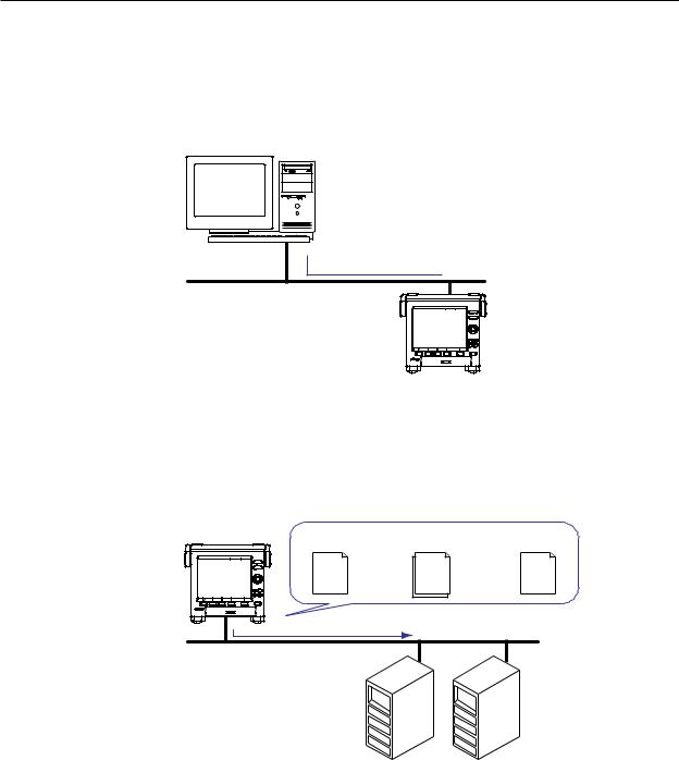
FTP Server
•You can access the MV from a PC via FTP. You can perform operations such as retrieving directory and file lists and transferring and deleting files from an external storage medium connected to the MV. You can also retrieve directory and file lists and transfer files from the internal memory.
•For the settings necessary to use this feature, see section 2.5.
PC
 Files on an external storage medium
Ethernet |
FTP server |
MV |
FTP Client
Automatic File Transfer
•You can use this feature to automatically transfer display, event, report, and snapshot data files that are created in the MV internal memory to an FTP. The result of the transfer is recorded in the FTP log. You can view the FTP log on the MV (see “Log Display” described later) or transmit the log to a PC using commands.
FTP client |
Data files to |
Transfer destination |
Transfer log |
|
be transferred |
(FTP server) information |
(FTP log) |
MV |
|
|
|
Data files |
|
|
|
Ethernet |
FTP server |
Primary |
Secondary |
|
|
You can specify two destination FTP servers: primary and secondary. If the primary
FTP server is down, the file is transferred to the secondary FTP server.
•For the settings necessary to use this feature, see section 2.6.
•FTP Test
•You can perform an FTP test by transferring a test file from the MV to an FTP server.
•You can view the result of the FTP test on the FTP log screen.
•For information on how to use this feature, see section 2.6.
1-2 |
IM MV1000-17E |

1.1 Ethernet Interface
Instrument Information Server
•You can use this feature to output the serial number, model name, and other information about an MV that is connected via an Ethernet network.
•You can use instrument information output commands (see section 4.12) with this feature.
Login
•You can use this feature when accessing the setting/measurement server, maintenance/test server, and FTP server functions via an Ethernet interface.
•For a description of the settings required to use this feature, see the MV1000/MV2000 User’s Manual (IM MV1000-01E).
•For the procedure to log into the setting/measurement server or the maintenance/test server, see appendix 3.
User Registration
Users are registered using the MV login feature. There are two user levels: administrator and user.
•Administrator
An administrator has privileges to use all the features of the setting/measurement server, maintenance/test server, and FTP server.
•User
A user has limited privileges to use the features of the setting/measurement server, maintenance/test server, and FTP server. For command limitations, see section 4.2.
•Setting/measurement server feature limitations
A user cannot change settings that affect the MV operation. A user can output measured data and setting data.
•Maintenance/test server feature limitations
A user cannot disconnect a connection between another PC and the MV. A user can disconnect the connection between the user’s own PC and the MV.
•FTP server feature limitations
A user cannot save or delete files on an external storage medium connected to the MV. A user can only load files.
•Application Timeout
This feature drops the connection with the PC if there is no data transfer for a given time. It prevents a PC from being connected to the MV indefinitely which would prohibit other users from making new connections.
1
Functions Communication of Overview
IM MV1000-17E |
1-3 |
1.1 Ethernet Interface
Web Server
•The MV screen can be displayed in Microsoft Internet Explorer.
•The following two pages are available.
•Monitor page: A dedicated monitoring screen.
•Operator page: You can switch the MV display and change or write messages. You can set access control (user name and password specified with the login function) for each page.
•The MV screen can be refreshed at a constant interval (approximately 10 s).
•The following information can be displayed.
•Alarm summary
•Measured and computed values of all channels
•Log (message log, error log, etc.)
•For Web server feature settings, see section 2.4.
•For a description of the monitor page and operator page operations, see section 2.4.
1-4 |
IM MV1000-17E |
1.1 Ethernet Interface
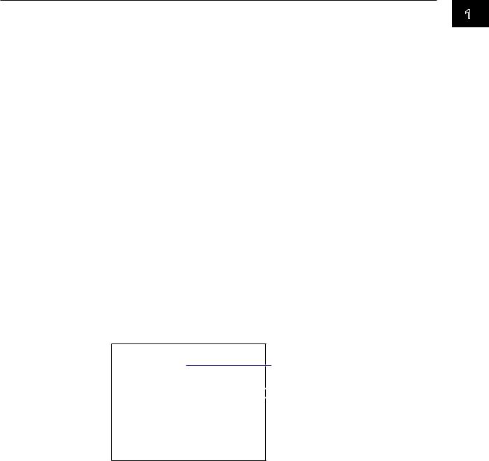
E-mail Transmission
E-mail Transmission
The available e-mail types are listed below. The MV can automatically transmit each e-mail type. You can specify two destination groups and specify one of the two
destination groups for each e-mail type. You can also set a header string for each type.
•Alarm e-mail
Reports alarm information when an alarm occurs or clears.
•System e-mail
When the MV recovers from a power failure, it reports the time of the power failure and the time of recovery.
Reports the detection of a memory shortage when it is detected.
Reports the error code and message when a media error occurs (when an error occurs on an external storage medium or when data cannot be stored due to insufficient free space on an external storage medium).
Reports the error code and message when an FTP client error (when data transfer fails using the FTP client feature) occurs.
•Scheduled e-mail
Transmits a message when the specified time is reached. You can use this feature to check that the network and e-mail transmission functions are working properly. You can specify a reference time and e-mail transmission interval for each destination.
•Report e-mail (only on models with the computation function, /M1 option) Transmits report results.
You can specify POP before SMTP if authentication is necessary before transmission. For e-mail transmission settings, see section 2.3.
For e-mail transmission formats, see section 2.3.
For the procedure to start/stop e-mail transmission, see section 2.3.
Example of an e-mail sent at a scheduled time
From: MV1000@daqstation.com
Date: Tue, 22 Jan 2008 08:00:45 +0900 (JST)
Subject: Periodic_data Subject
To: user1@daqstation.com, user2@mvadv.co.jp
LOOP1 |
|
|
Header 1 |
|
|
|
|||
TEMPERATURE |
|
|
Header 2 |
|
|
||||
Time |
|
|
||
Host name |
|
|
||
MV1000 |
|
|
||
Time of transmission |
|
|
||
01/05 08:00:01 |
|
|
|
|
E-mail Transmission Test
•You can test e-mail transmission by sending a test mail from the MV to a destination.
•You can view the test result in the e-mail log screen.
•For information on how to use this feature, see section 2.3.
1
Functions Communication of Overview
IM MV1000-17E |
1-5 |

1.1 Ethernet Interface
SNTP Server/Client
The client feature retrieves time information from a specified SNTP server at a specified interval.
The server feature can provide time information to MVs and other devices connected to the same network.
DHCP Client
You can use this feature to automatically obtain an IP address from a DHCP server. You can manually retrieve or release network information.
Other Features
Ethernet Interface Connection Status Check
You can check the Ethernet interface connection status on the MV rear panel or the MV screen.
For a description of the connection status indicators, see section 2.2.
Keepalive (TCP extension feature)
This feature drops the connection if there is no response to a test packet that is periodically transmitted at the TCP level.
For the settings necessary to use this feature, see section 2.2.
Log Display
You can display operation logs on the MV log screen. You can also check logs using communication commands. The Web screen can also display logs (except communication and DHCP logs).
• Error log screen: A log of operation errors
• Communication log screen: A setting/measurement server communication input/
|
|
output log |
• |
FTP log screen: |
A log of file transfers carried out using the FTP client |
|
|
feature |
• |
WEB log screen: |
A Web server operation log |
• |
Mail log screen: |
A log of e-mail transmissions |
• |
Login log screen: |
A login/logout log |
• |
SNTP log screen: |
An SNTP server access log |
• |
DHCP log screen: |
A DHCP server access log |
• |
Modbus log screen: |
A Modbus status (master/client operating condition) log |
For the procedure to show the log screen and details on the displayed contents, see the
MV1000/MV2000 User’s Manual (IM MV1000-01E). For details on the Modbus status log, see section 2.8.
For details on how to output logs using communication commands, see section 5.2. For details on how to show logs on the Web screen, see section 2.4.
1-6 |
IM MV1000-17E |

1.2Serial Interface
The MV supports serial communications via the RS-232 and RS-422/RS-485. This chapter gives an overview of the MV serial communication functions.
Modbus Communications
•The MV can connect to a Modbus device and read and write to the device’s internal registers. See section 1.3 for details.
Setting/Measurement Server
•You can use this feature to set almost all of the settings that can be configured from the MV front panel keys. See section 1.1 for details.
•For the settings necessary to use this feature, see section 3.3.
1
Functions Communication of Overview
IM MV1000-17E |
1-7 |
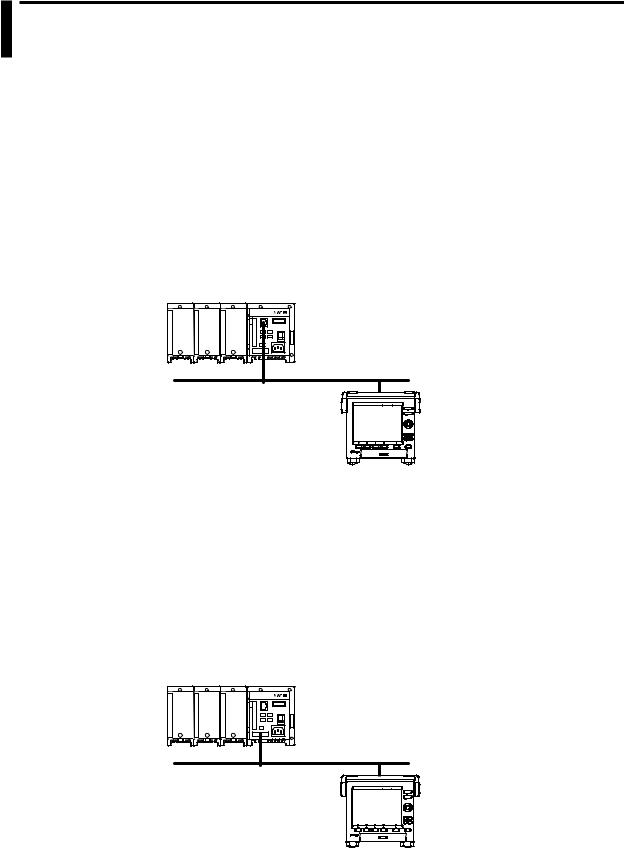
1.3Modbus Protocol
Modbus Client/Master
•The MV can connect to a Modbus server or slave device and read and write to the device’s internal registers.
The MV can handle the data that is read from the registers as communication input data on a computation channel (computation function1). The MV can also handle the data on an external input channel.2
The MV can write measured and computed data to the registers.
1 /M1 option.
2 MV2000 with the /MC1 option.
•For details on the Modbus function codes that the MV supports, see section 7.3.
•For the settings to use the Modbus client feature, see section 2.9. For the settings to use the Modbus master feature, see sections 3.3, 3.5, and 3.6.
Server Device Connection Example
Modbus server device |
Ethernet
MV
MV (client)
Modbus Server/Slave
•A Modbus client (master) device can connect to an MV, a Modbus server (slave) device, to read the measured, computed,1 or external input2 data that is written in the input register or to read or write data to communication input data1 or to an external input channel2 through the MV hold register.
1 /M1 option.
2 MV2000 with the /MC1 option.
•For details on the Modbus function codes that the MV supports, see section 7.3.
•For the settings to use the Modbus client feature, see section 2.8. For the settings to use the Modbus master feature, see sections 3.3, 3.4, and 3.6.
Example of a Connection with a Modbus Master Device
Modbus master device |
Serial communication
MV
MV (slave)
1-8 |
IM MV1000-17E |
Chapter 2 Using the Ethernet Interface
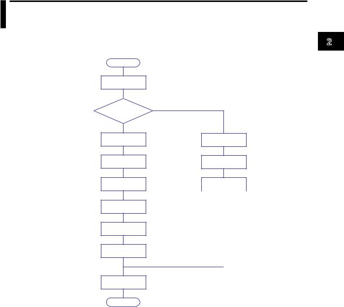
2.1Workflow for Using the Ethernet Interface
Follow the flowchart below to configure Ethernet communication.
Start
Connect the ports
IP address assignment method
Fixed IP address
Set the IP address
Set the subnet mask
Set the default gateway
Set the host name (optional)
Set the domain name (optional)
Set the DNS server search order
Automatically assigned IP address (DHCP)
Set the Obtain DNS info item
Set the Host name registration
Set the host name
|
|
Not set when Obtain |
Set the domain |
||
name |
DNS info is set to Use. |
|
|
|
|
Set the DNS server |
Not set when Obtain |
|
search order |
DNS info is set to Use. |
|
|
|
|
Set the domain suffix search order
End
2
Interface Ethernet the Using
IM MV1000-17E |
2-1 |
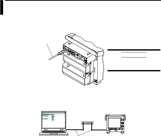
2.2Connecting the MV
Connecting to the Port
Ethernet Port
Connect an Ethernet cable to the Ethernet port on the MV rear panel.
Ethernet cable
CAUTION
Be sure to connect an Ethernet cable with an FCC-compliant plug. Otherwise, the MV may malfunction.
Connecting to a PC
Connect the MV to a PC via a hub. To make a one-to-one connection, see the figure below. You can connect multiple MVs to a single PC in the same way.
PC
MV
Hub
Ethernet cable
2-2 |
IM MV1000-17E |
2.2 Connecting the MV
Setting the IP Address, Host Information, and DNS
MV1000
◊Press MENU and then select Menu tab > Basic setting mode > Menu tab > Communication (Ethernet) > IP address
◊Press MENU and then select MENU tab > Basic setting mode > Menu tab > Communication (Ethernet) > Host settings
◊Press MENU and then select MENU tab > Basic setting mode > Menu tab > Communication (Ethernet) > DNS settings
MV2000
◊Press MENU and then select MENU tab > Basic setting mode > Menu tab > Communication (Ethernet) > IP address, Host settings
◊Press MENU and then select Menu tab > Basic setting mode > Menu tab > Communication (Ethernet) > DNS settings
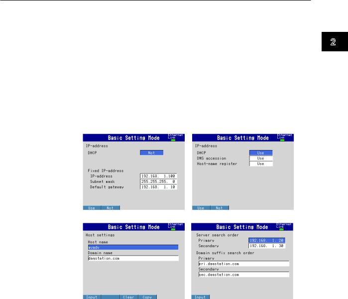
IP address settings (DHCP set to Not) |
IP address settings (DHCP set to Use) |
2
Interface Ethernet the Using
Host name settings |
DNS settings |
Set the IP address to a fixed IP address or obtain it automatically (DHCP).
Consult with your network administrator for network parameters such as the IP address, subnet mask, default gateway, and DNS.
IM MV1000-17E |
2-3 |

2.2 Connecting the MV
When Using a Fixed IP Address
•DHCP
Set DHCP to Not.
•IP address
Set the IP address to be assigned to the MV.
•Subnet mask
Set the subnet mask according to the system or network that the MV belongs to.
•Default gateway
Set the gateway IP address.
•Host name
Set the MV host name using up to 64 alphanumeric characters. You do not have to set this parameter.
•Domain name
Set the name of the domain that the MV belongs to using up to 64 alphanumeric characters. You do not have to set this parameter.
•Server search order
Register up to two IP addresses for the primary and secondary DNS servers.
•Domain suffix search order
Set up to two domain suffixes: primary and secondary.
When Obtaining an IP Address Automatically (DHCP)
•DHCP
Set DHCP to Use.
•Obtain DNS info
To automatically obtain the DNS server address, select Use. Otherwise, select Not. If you select Not, you must set the server search order.
•Host name registration
To automatically register the host name to the DNS server, select Use.
•Host name
Set the MV host name using up to 64 alphanumeric characters.
•Domain name
Set the name of the domain that the MV belongs to using up to 64 alphanumeric characters. This parameter is valid when Obtain DNS info is set to Not.
•Server search order
Register up to two IP addresses for the primary and secondary DNS servers.
•Domain suffix search order
Set up to two domain suffixes: primary and secondary.
2-4 |
IM MV1000-17E |
2.2 Connecting the MV
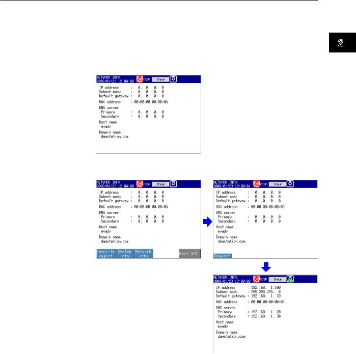
Requesting/Clearing Network Information through DHCP
You can manually request or release IP address and other network information. This operation applies when DHCP is set to Use. First switch to the network information screen and then execute the request or release (clear) operation.
Requesting Network Information
1.Switch to the network information screen.
◊ Press FUNC > Network info
2.Request network information.
◊ Press FUNC > Network info > Request
The retrieved network information appears.
2
Interface Ethernet the Using
IM MV1000-17E |
2-5 |
2.2 Connecting the MV
Clearing Network Information
1.Switch to the network information screen.
◊ Press FUNC > Network info
2.Release (clear) the network information.
◊ Press FUNC > Network info > Release
The network information is released. |
DISP/ENTER key |
2-6 |
IM MV1000-17E |
2.2 Connecting the MV
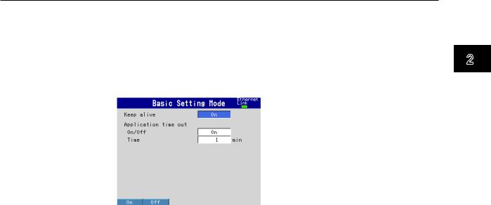
Setting the Communication Conditions
MV1000
◊Press MENU and then select Menu tab > Basic setting mode > Menu tab > Communication (Ethernet) > Keep alive, Timeout
MV2000
◊Press MENU and then select Menu tab > Basic setting mode > Menu tab > Communication (Ethernet) > Keep alive, Application time out
Setting the Keepalive Feature
To disconnect when there is no response to the test packets that are periodically sent, select On. Otherwise, select Off.
Setting the Application Timeout
•Selecting On or Off
To use the application timeout feature, select On. Otherwise, select Off. If you select On, the Time parameter appears.
•Time
Set the timeout value in the range of 1 to 120 (minutes).
Checking the Communication Status
You can check the Ethernet communication status with the LED lamp that is provided on the MV rear panel Ethernet connector or the Ethernet link that is shown at the upper right of the basic setting screen.
2
Interface Ethernet the Using
IM MV1000-17E |
2-7 |
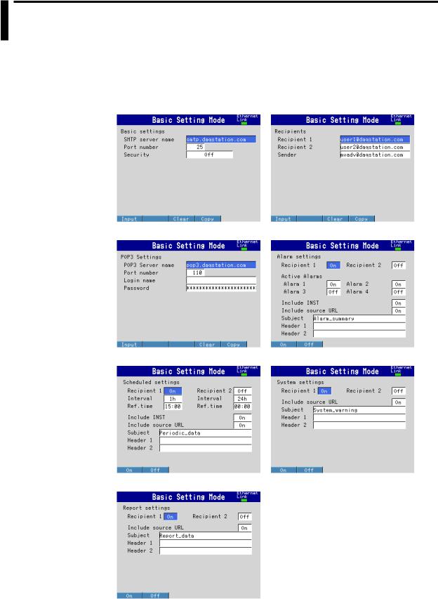
2.3Sending E-mail Messages
Configuring E-mail Transmission
Configure the server, and set the contents of the e-mail.
◊Press MENU and then select Menu tab > Basic setting mode > Menu tab > Communication (Ethernet) > E-Mail
Basic settings |
Recipients |
POP3 Settings |
Alarm settings |
Scheduled settings |
System settings |
Report settings
2-8 |
IM MV1000-17E |

2.3 Sending E-mail Messages
Basic Settings
Specify the SMTP server and POP before SMTP.
•SMTP server name
Enter the host name or IP address of the SMTP server.
•Port number
Unless specified otherwise, set the number to the default value. The default value is 25.
•Security
If you need to use POP before SMTP, set Security to PbS.
Recipients
Set the recipient e-mail addresses.
•Recipient 1 and Recipient 2
Enter e-mail addresses. You can enter multiple addresses in each recipient box. Separate each address with a space. You can enter up to 150 characters.
•Sender
Enter the sender e-mail address. You can enter up to 64 characters.
POP3 Settings
If you need to use POP before SMTP, specify the POP3 server.
 For the POP3 login procedure, see “Setting the POP3 Server Connection” in this section.
•POP3 Server name
Enter the host name or IP address of the POP3 server.
•Port number
Unless specified otherwise, set the number to the default value. The default value is 110.
•Login name
Enter the POP3 server login name.
•Password
Enter the POP3 server login password. You can enter up to 32 characters.
Alarm Settings
Specify the settings for sending e-mail when alarms occur or clear.
•Recipient 1 and Recipient 2
Specify the recipients. For Recipient 1 and Recipient 2, select On to send e-mail or Off to not send e-mail.
•Active Alarms
Sends an e-mail when an alarm occurs or clears. For alarms 1 to 4, select On to send e-mail or Off to not send e-mail.
•Include INST
Select On to attach instantaneous value data. The data that is attached is the instantaneous value that is measured at the time the e-mail is transmitted.
•Include source URL
Select On to attach the source URL. You can attach the URL when the Web server is enabled.
•Subject
Enter the subject of the e-mail using up to 32 alphanumeric characters. The default subject is Alarm_summary.
•Header 1 and Header 2
Enter Header 1 and Header 2 using up to 64 characters.
2
Interface Ethernet the Using
IM MV1000-17E |
2-9 |

2.3 Sending E-mail Messages
Scheduled Settings
Specify the settings for sending e-mail at scheduled times.
•Recipients
Specify the recipients. For Recipient 1 and Recipient 2, select On to send e-mail or Off to not send e-mail.
•Interval
For Recipient 1 and Recipient 2, set the interval for sending e-mail to 1, 2, 3, 4, 6, 8, 12, or 24 hours.
•Ref.time
Enter the time reference for sending e-mail to Recipient 1 and Recipient 2 at a specified interval.
•Include INST, Include source URL, Subject, Header
These parameters are the same as those listed under “Alarm Settings.” The default subject is Periodic_data.
System Settings
Specify the settings for sending e-mail when the MV recovers from a power failure, when there is a memory shortage, and when an error occurs.
•Recipients
Specify the recipients. For Recipient 1 and Recipient 2, select On to send e-mail or Off to not send e-mail.
•Include source URL, Subject, and Header
These parameters are the same as those listed under “Alarm Settings.” The default subject is System_warning.
Report Settings
Specify the settings for sending e-mail when reports are generated.
•Recipients
Specify the recipients. For Recipient 1 and Recipient 2, select On to send e-mail or Off to not send e-mail.
•Include source URL, Subject, and Header
These parameters are the same as those listed under “Alarm Settings.” The default subject is Report_data.
2-10 |
IM MV1000-17E |
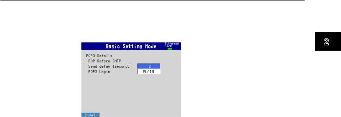
2.3 Sending E-mail Messages
Setting the POP3 Server Connection
Specify the operation for connecting to the POP server.
◊Press MENU and then select Menu tab > Basic setting mode > Environment tab > Communication > POP3 Details
Send delay [second]
Enter the wait time from POP3 server authentication until transmission. Set a value in the range of 0 to 10 (seconds).
POP3 Login
To send the POP3 server login password without encryption, set POP3 Login to PLAIN. To send the password with encryption, set POP3 Login to APOP.
E-mail Test
◊Press FUNC and then select E-mail test > Recipient1 or Recipient2
You can send a test e-mail to check the e-mail settings.
Enabling/Disabling the E-mail Transmission Function
Enabling the E-mail Transmission Function
◊Press FUNC and then select E-Mail start
The e-mail transmission function is enabled.
Disabling the E-mail Transmission Function
◊Press FUNC and then select E-Mail stop
The e-mail transmission function is disabled. Unsent e-mail messages are discarded.
E-mail Retransmission
If an e-mail transmission fails, the MV retransmits the message up to three times at 30-s, 1-minute, or 3-minute intervals. If retransmission fails, the MV discards the e-mail message.
2
Interface Ethernet the Using
IM MV1000-17E |
2-11 |

2.3 Sending E-mail Messages
E-mail Format
The formats of alarm, scheduled, system, report, and test e-mails are given below. For details on the displayed items that are common to all e-mails, see “Display Items Common to All Formats” in this section.
Alarm Notification E-mail Format
•Subject
Subject: [Alarm Summary]
•Syntax header1CRLF header2CRLF CRLF
Alarm_summary.CRLF <Host_name>CRLF hostCRLF
CRLF
<CH>ccc···cCRLF <Type>lqCRLF <aaa>mo/dd_hh:mi:ssCRLF CRLF
<Inst._value>CRLF mo/dd_hh:mi:ssCRLF ccc···c=ddd···dCRLF
·····························
CRLF
Access_the_following_URL_in_order_to_look_at_a_screen.CRLF http://host.domain/CRLF
CRLF
ccc···c |
Channel number or tag name |
|
|
(Up to 16 characters. Channels set to Skip or Off are not transmitted. |
|
l |
See section 4.3 for channel numbers.) |
|
Alarm level (1 to 4) |
||
q |
Alarm type (H, L, h, l, R, or r) |
|
|
H(high limit alarm), L(low limit alarm), h(difference high limit alarm), |
|
|
l(difference low limit alarm), R(high limit on rate-of-change alarm), |
|
aaa |
and r(low limit on rate-of-change alarm) |
|
Alarm status (off or on) |
||
ddd···d |
Measured/computed value (up to 10 digits including the sign and |
|
|
decimal point) + unit (up to six characters) |
|
|
+OVER: |
Positive range-out |
|
-OVER: |
Negative range-out |
|
Burnout: |
Burnout data |
|
*****: |
Error data |
The MV transmits the channel numbers, alarm types, and alarm statuses for up to 10 events in a single e-mail.
2-12 |
IM MV1000-17E |

2.3 Sending E-mail Messages
Scheduled E-mail Format
•Subject
Subject: [Periodic Data]
•Syntax header1CRLF header2CRLF CRLF
Periodic_data.CRLF <Host_name>CRLF hostCRLF
CRLF
<Time>CRLF mo/dd_hh:mi:ssCRLF CRLF
E-mail_message(s)_did_not_reach_intended_recipient(s).CRLF ttt···t
Count=nnCRLF mo/dd_hh:mi:ssCRLF
····························
CRLF
<Inst._value>CRLF mo/dd_hh:mi:ssCRLF ccc···c=ddd···dCRLF
····························
CRLF
Access_the_following_URL_in_order_to_look_at_a_screen.CRLF http://host.domain/CRLF
CRLF
ccc···c |
Channel number or tag name |
||
|
(Up to 16 characters. Channels set to Skip or Off are not transmitted. |
||
|
See section 4.3 for channel numbers.) |
||
ttt···t |
Type of discarded e-mail |
||
|
Alarm_summary: |
Alarm e-mail |
|
|
Periodic_data: |
Scheduled e-mail |
|
|
System_warning: |
System e-mail |
|
nn |
Report_data: |
|
Report e-mail |
Number of discarded e-mails |
|||
ddd···d |
Measured/computed value (up to 10 digits including the sign and |
||
|
decimal point) + unit (up to six characters) |
||
|
+OVER: |
Positive range-out |
|
|
-OVER: |
Negative range-out |
|
|
Burnout: |
Burnout data |
|
|
*****: |
Error data |
|
The time that follows the type and count of discarded e-mails is the time when the last e-mail is discarded.
2
Interface Ethernet the Using
IM MV1000-17E |
2-13 |

2.3 Sending E-mail Messages
System E-mail (Power Failure) Format
•Subject
Subject: [System_warning]
•Syntax header1CRLF header2CRLF CRLF
Power_failure.CRLF <Host_name>CRLF hostCRLF
CRLF
<Power_fail>mo/dd_hh:mi:ssCRLF <Power_on>mo/dd_hh:mi:ssCRLF CRLF
Access_the_following_URL_in_order_to_look_at_a_screen.CRLF http://host.domain/CRLF
CRLF
System E-mail (Memory Full) Format
•Subject
Subject: [System_warning]
•Syntax header1CRLF header2CRLF CRLF
Memory_full.CRLF <Host_name>CRLF hostCRLF
CRLF
<Memory_remain>ppp···pMbytesCRLF <Memory_blocks>bbb/400CRLF <Media_remain>rrr···rMbytesCRLF CRLF
Access_the_following_URL_in_order_to_look_at_a_screen.CRLF http://host.domain/CRLF
CRLF
ppp···p |
Remaining amount of internal memory |
bbb |
Number of unsaved blocks (0 to 400) |
rrr···r |
Remaining free space on the external storage medium (when an |
|
external storage medium is connected) |
2-14 |
IM MV1000-17E |

2.3 Sending E-mail Messages
System E-mail (Error) Format
•Subject
Subject: [System_warning]
•Syntax header1CRLF header2CRLF CRLF
Error.CRLF <Host_name>CRLF hostCRLF
CRLF mo/dd_hh:mi:ssCRLF ERROR:fffCRLF
····························
“Operation_aborted_because_an_error_was_found_in_media.”CRLF CRLF
Access_the_following_URL_in_order_to_look_at_a_screen.CRLF http://host.domain/CRLF
CRLF
fff Error number (200, 201, 211, or 281 to 285)
The displayed error message varies depending on the error type. For details on errors, see the MV1000/MV2000 User’s Manual (IM MV1000-01E).
Report E-mail Format
•Subject
Subject: [Report_data]
•Syntax header1CRLF header2CRLF CRLF ti_report.CRLF <Host_name>CRLF hostCRLF
CRLF mo/dd_hh:mi:ssCRLF <CH>ccc···cCRLF <tp>eee···eCRLF <tp>eee···eCRLF <tp>eee···eCRLF <tp>eee···eCRLF <Unit>uuu···uCRLF
····························
CRLF
Access_the_following_URL_in_order_to_look_at_a_screen.CRLF http://host.domain/CRLF
CRLF
ti |
Contents of the report e-mail (hourly, daily, weekly, or monthly report) |
ccc···c |
Channel number or tag name |
|
(Up to 16 characters. Channels set to Skip or Off are not transmitted. |
|
See section 4.3 for channel numbers.) |
2
Interface Ethernet the Using
IM MV1000-17E |
2-15 |
Loading...