


SGS Thomson Microelectronics TL431IN, TL431ID, TL431CZ, TL431IZ, TL431AIZ Datasheet
...
|
TL431 |
PROGRAMMABLE VOLTAGE REFERENCE
.ADJUSTABLE OUTPUT VOLTAGE :
.2.5 to 36V
.SINK CURRENT CAPABILITY : 1 to 100mA
.TYPICAL OUTPUT IMPEDANCE : 0.22Ω 1% AND 2% VOLTAGE PRECISION
DESCRIPTION
The TL431 is a programmable shunt voltage reference with guaranteed temperature stability over the entire temperature range of operation.
The output voltage may be set to any value between Vref (approximately 2.5V) and 36V with two external resistors.
The TL431 operates with a wide current range from 1 to 100mA with a typical dynamic impedance of 0.22Ω.
Z
TO92
(Plastic Package)
N
DIP8
(Plastic Package)
D
SO8
(Batwing Plastic Micropackage)
ORDER CODES
Part number |
Temperature Range |
|
Package |
|
|
Z |
N |
D |
|||
|
|
||||
TL431C/AC |
0oC, +70oC |
• |
• |
• |
|
TL431I/AI |
-40oC, +105oC |
• |
• |
• |
PIN CONNECTIONS
|
TO92 |
|
DIP8 |
|
|
|
|
SO8 |
|
|
|
|
(Top view) |
|
(Top view) |
|
|
|
(Top view) |
|
|
||
|
|
8 |
7 |
6 |
5 |
|
8 |
7 |
6 |
5 |
|
Ca th o d e Ano d e Re fere n c e |
|
|
1 |
- Cathode |
|
|
|
1 |
- Cathode |
||
1 |
2 |
3 |
|
|
|
|
|
||||
|
|
2 |
- N.C. |
|
|
|
2 |
- Anode |
|||
|
|
|
|
|
|
|
|
||||
|
|
|
|
|
3 |
- N.C. |
|
|
|
3 |
- Anode |
|
|
|
|
|
4 |
- N.C. |
|
|
|
4 |
- N.C. |
|
|
|
|
|
5 |
- N.C. |
|
|
|
5 |
- N.C. |
|
|
|
|
|
6 |
- Anode |
|
|
|
6 |
- Anode |
|
|
|
|
|
7 |
- N.C. |
|
|
|
7 |
- Anode |
|
|
|
|
|
8 |
- Reference |
|
|
|
8 |
- Reference |
|
|
1 |
2 |
3 |
4 |
|
1 |
2 |
3 |
4 |
|
November 1998 |
1/9 |

TL431
ABSOLUTE MAXIMUM RATINGS
Symbol |
Parameter |
Value |
Unit |
VKA |
Cathode to Anode Voltage |
37 |
V |
IK |
Continuous Cathode Current Range |
-100 to +150 |
mA |
Iref |
Reference Input Current Range |
-0.05 to +10 |
mA |
Toper |
Operating Free-air Temperature Range TL431C/AC |
0 to +70 |
oC |
|
TL431I/AI |
-40 to +105 |
|
Tstg |
Storage Temperature Range |
-65 to +150 |
oC |
OPERATING CONDITIONS
Symbol |
Parameter |
Value |
Unit |
VKA |
Cathode to Anode Voltage |
Vref to 36 |
V |
IK |
Cathode Current |
1 to 100 |
mA |
ELECTRICAL CHARACTERISTICS
Tamb = 25oC (unless otherwise specified)
Symbol |
|
|
Parameter |
|
|
TL431C |
|
TL431AC |
|
Unit |
|
|
|
|
Min. Typ. Max. Min. Typ. Max. |
||||||
|
|
|
|
|
|
|
||||
Vref |
Reference Input Voltage - (figure 1) |
Tamb = 25oC |
|
|
|
|
V |
|||
|
VKA = Vref, IK = 10mA |
|
2.44 2.495 |
2.55 |
2.47 2.495 |
2.52 |
|
|||
|
|
|
Tmin. ≤ Tamb |
≤ Tmax. |
2.423 |
2.567 |
2.453 |
2.537 |
|
|
Vref |
Reference Input Voltage Deviation Over |
|
|
|
|
|
mV |
|||
|
Temperature Range - (figure 1, note1) |
|
|
|
|
|
|
|||
|
VKA = Vref, IK = 10mA, Tmin. ≤ Tamb ≤ Tmax. |
3 |
17 |
3 |
15 |
|
||||
Vref |
Ratio of Change in Reference Input Voltage to |
|
|
|
|
mV/V |
||||
VKA |
Change in Cathode to Anode Voltage - (figure 2) |
-1.4 |
-2.7 |
-1.4 |
-2.7 |
|
||||
IK = 10mA |
|
VKA = 10V to Vref |
|
|||||||
|
|
|
||||||||
|
|
|
VKA = 36V to 10V |
-1 |
-2 |
-1 |
-2 |
|
||
Iref |
Reference Input Current - (figure 2) |
|
|
|
|
|
μA |
|||
|
IK = 10mA, R1 = 10kΩ, R2 = ∞ |
|
|
|
|
|
|
|
||
|
|
|
Tamb = 25oC |
|
1.8 |
4 |
1.8 |
4 |
|
|
|
|
|
Tmin. ≤ Tamb ≤ Tmax. |
|
5.2 |
|
5.2 |
|
||
Iref |
Reference Input Current Deviation Over |
|
|
|
|
|
μA |
|||
|
Temperature Range - (figure 2) |
|
|
|
|
|
|
|
||
|
IK = 10mA, R1 = 10kΩ, R2 = ∞ |
|
|
0.4 |
1.2 |
0.4 |
1.2 |
|
||
|
|
|
Tmin. ≤ Tamb |
≤ Tmax. |
|
|
|
|
|
|
Imin |
Minimum Cathode Current for Regulation - (figure 1) |
|
|
|
|
mA |
||||
|
VKA = Vref |
|
|
|
|
0.5 |
1 |
0.5 |
0.6 |
|
Ioff |
Off-State Cathode Current - (figure 3) |
|
2.6 |
1000 |
2.6 |
1000 |
nA |
|||
|ZKA| |
Dynamic Impedance - (figure 1, note 2) |
|
|
|
|
|
Ω |
|||
|
VKA = Vref, |
IK = 1 to 100mA, f |
≤ 1kHz |
0.22 |
0.5 |
0.22 |
0.5 |
|
||
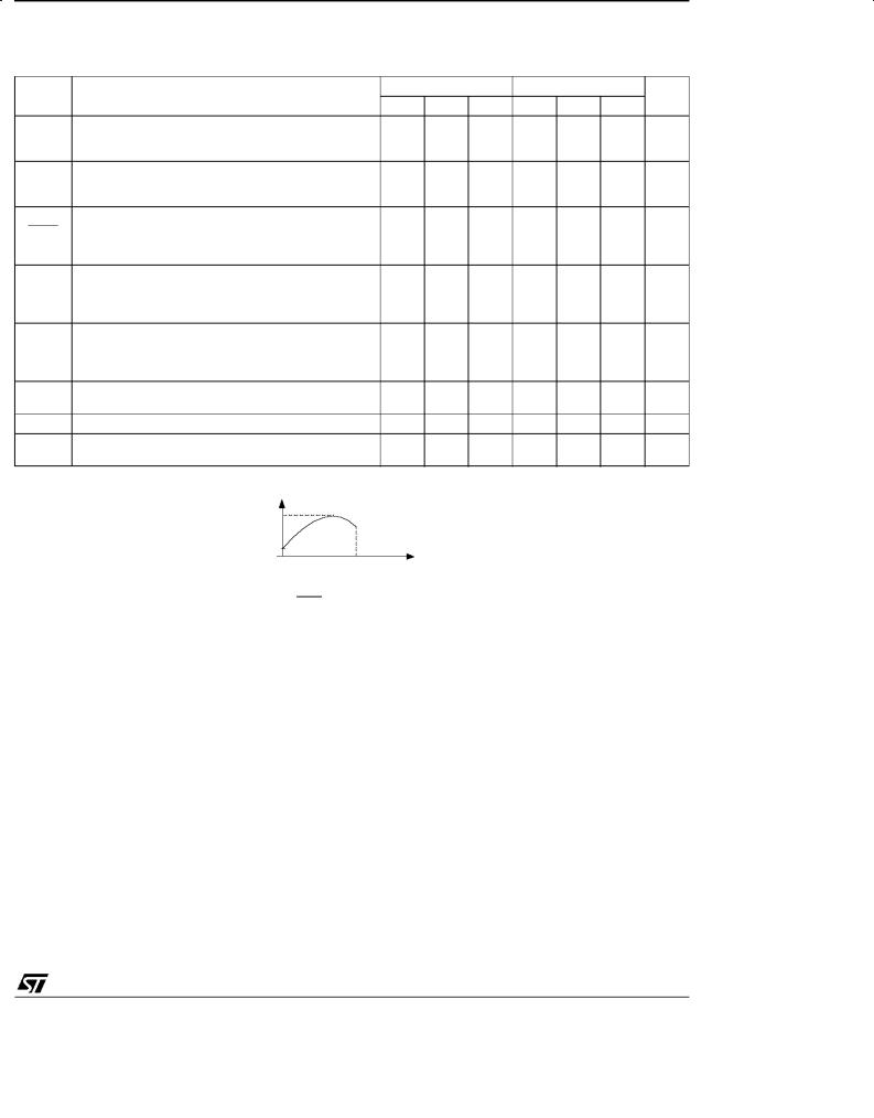
Notes : 1. |
Vref is defined as the difference between the maximum and minimum values obtained over the full temperature |
|
||||||||
|
range. |
|
|
|
|
|
|
|
|
|
|
Vref = Vref max. - Vref min |
V re f ma x. |
|
|
|
|
|
|
||
|
|
|
|
|
|
|
|
|
||
|
|
|
Vre fm in. |
|
|
|
|
|
|
|
|
|
|
|
T1 |
T2 |
Tempe ra tur e |
|
|
|
|
|
|
|
|
|
|
|
|
|
||
2. |
The dynamic Impedance is defined as |ZKA| = |
VKA |
|
|
|
|
|
|||
|
|
|
|
|
IK |
|
|
|
|
|
2/9
|
|
|
|
|
|
|
|
|
|
TL431 |
ELECTRICAL CHARACTERISTICS |
|
|
|
|
|
|
|
|||
Tamb = 25oC (unless otherwise specified) |
|
|
|
|
|
|
||||
Symbol |
|
|
Parameter |
|
|
TL431I |
|
TL431AI |
|
Unit |
|
|
|
|
Min. Typ. Max. Min. Typ. Max. |
||||||
|
|
|
|
|
|
|
||||
Vref |
Reference Input Voltage - (figure 1) |
Tamb = 25oC |
|
|
|
|
V |
|||
|
VKA = Vref, IK = 10mA |
|
2.44 2.495 |
2.55 |
2.47 2.495 |
2.52 |
|
|||
|
|
|
Tmin. ≤ Tamb |
≤ Tmax. |
2.41 |
2.58 |
2.44 |
2.55 |
|
|
Vref |
Reference Input Voltage Deviation Over |
|
|
|
|
|
mV |
|||
|
Temperature Range - (figure 1, note1) |
|
|
|
|
|
|
|||
|
VKA = Vref, IK = 10mA, Tmin. ≤ Tamb ≤ Tmax. |
7 |
30 |
7 |
30 |
|
||||
Vref |
Ratio of Change in Reference Input Voltage to |
|
|
|
|
mV/V |
||||
VKA |
Change in Cathode to Anode Voltage - (figure 2) |
-1.4 |
-2.7 |
-1.4 |
-2.7 |
|
||||
IK = 10mA |
|
VKA = 10V to Vref |
|
|||||||
|
|
|
||||||||
|
|
|
VKA = 36V to 10V |
-1 |
-2 |
-1 |
-2 |
|
||
Iref |
Reference Input Current - (figure 2) |
|
|
|
|
|
μA |
|||
|
IK = 10mA, R1 = 10kΩ, R2 = ∞ |
|
|
|
|
|
|
|
||
|
|
|
Tamb = 25oC |
|
1.8 |
4 |
1.8 |
4 |
|
|
|
|
|
Tmin. ≤ Tamb ≤ Tmax. |
|
6.5 |
|
6.5 |
|
||
Iref |
Reference Input Current Deviation Over |
|
|
|
|
|
μA |
|||
|
Temperature Range - (figure 2) |
|
|
|
|
|
|
|
||
|
IK = 10mA, R1 = 10kΩ, R2 = ∞ |
|
|
0.8 |
2.5 |
0.8 |
1.2 |
|
||
|
|
|
Tmin. ≤ Tamb |
≤ Tmax. |
|
|
|
|
|
|
Imin |
Minimum Cathode Current for Regulation - (figure 1) |
|
|
|
|
mA |
||||
|
VKA = Vref |
|
|
|
|
0.5 |
1 |
0.5 |
0.7 |
|
Ioff |
Off-State Cathode Current - (figure 3) |
|
2.6 |
1000 |
2.6 |
1000 |
nA |
|||
|ZKA| |
Dynamic Impedance - (figure 1, note 2) |
|
|
|
|
|
Ω |
|||
|
VKA = Vref, |
IK = 1 to 100mA, f |
≤ 1kHz |
0.22 |
0.5 |
0.22 |
0.5 |
|
||
Notes : 1. |
Vref is defined as the difference between the maximum and minimum values obtained over the full temperature |
|
||||||||
|
range. |
|
|
|
|
|
|
|
|
|
|
Vref = Vref max. - Vref min |
V re f ma x. |
|
|
|
|
|
|
||
|
|
|
|
|
|
|
|
|
||
|
|
|
Vre fm in. |
|
|
|
|
|
|
|
|
|
|
|
T1 |
T2 |
Tempe ra tur e |
|
|
|
|
|
|
|
|
|
|
|
|
|
||
2. |
The dynamic Impedance is defined as |ZKA| = |
VKA |
|
|
|
|
|
|||
|
|
|
|
|
IK |
|
|
|
|
|
3/9
 Loading...