


TLP270M
SGS Thomson Microelectronics TLP270M, TLP270G-1, TLP270G, TLP200M, TLP200G-1 Datasheet
...
TLPxxM/G/G-1
ApplicationSpecific Discretes
A.S.D.
MAINAPPLICATIONS
Anysensitive telecomequipmentrequiringprotectionagainst lightning :
Analogand ISDN line cards
MainDistributionFrames
Terminaland transmissionequipment
Gas-tubereplacement
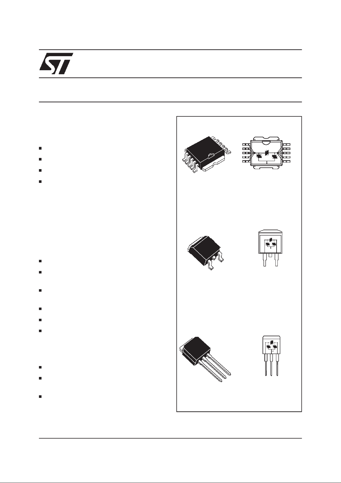
DESCRIPTION
The TLPxxM/G/G-1 series are tripolar transient
surge arrestors used for primary and secondary
protectionin sensitivetelecomequipment.
FEATURES
TRIPOLARCROWBAR PROTECTION
VOLTAGE RANGE SELECTED FOR
TELECOMAPPLICATIONS
PROTECTIONfor TELECOM LINE
TRIPOLAR OVERVOLTAGE
GND
TIP
PowerSO-10TMTLPxxM
GND
TAB
GND
D2PAK TLPxxG
RINGTIP
RINGTIP
RING
RINGTIP
RINGTIP
RINGTIP
REPETITIVEPEAK PULSE CURRENT:
= 100A (10/ 1000µs)
I
PP
HOLDINGCURRENT: I
= 150mA
H
LOWCAPACITANCE: C = 110 pF typ.
LOWLEAKAGECURRENT: I
=5µA max
R
BENEFITS
No ageing and no noise.
If destroyed, the TLPxxM/G/G-1 falls into short
circuit,still ensuringprotection.
Access to Surface Mount applications thanks to
TM
the PowerSO-10
TM: ASD and PowerSO-10 are trademarks of ST Microelectronics.
September 1998 - Ed : 3C
andD2PAKpackage.
2
I
PAK TLPxxG-1
GND
TAB
GND RINGTIP
1/14
TLPxxM/G/G-1
COMPLIESWITH THE
FOLLOWINGSTANDARDS:
PeakSurge
Voltage
(V)
Voltage
Waveform
(µs)
Current
Waveform
(µs)
Admissible
Ipp
(A)
Necessary
Resistor
CCITTK20 4000 10/700 5/310 100 VDE0433
4000 10/700 5/310 100 VDE0878 4000 1.2/50 1/20 100 IEC-1000-4-5 level 4
level 4
FCC Part68, lightningsurge
type A
FCC Part68, lightningsurge
1500
800
1000 5/320 5/320 25 -
10/700
1.2/50
10/160
10/560
5/310
8/20
10/160
10/560
100
100
200
100
type B
BELLCORETR-NWT-001089
FIRSTLEVEL
BELLCORETR-NWT-001089
2500
1000
2/10
10/1000
2/10
10/1000
500
100
5000 2/10 2/10 500 SECONDLEVEL
CNETI31-24 4000 0.5/700 0.8/310 100 -
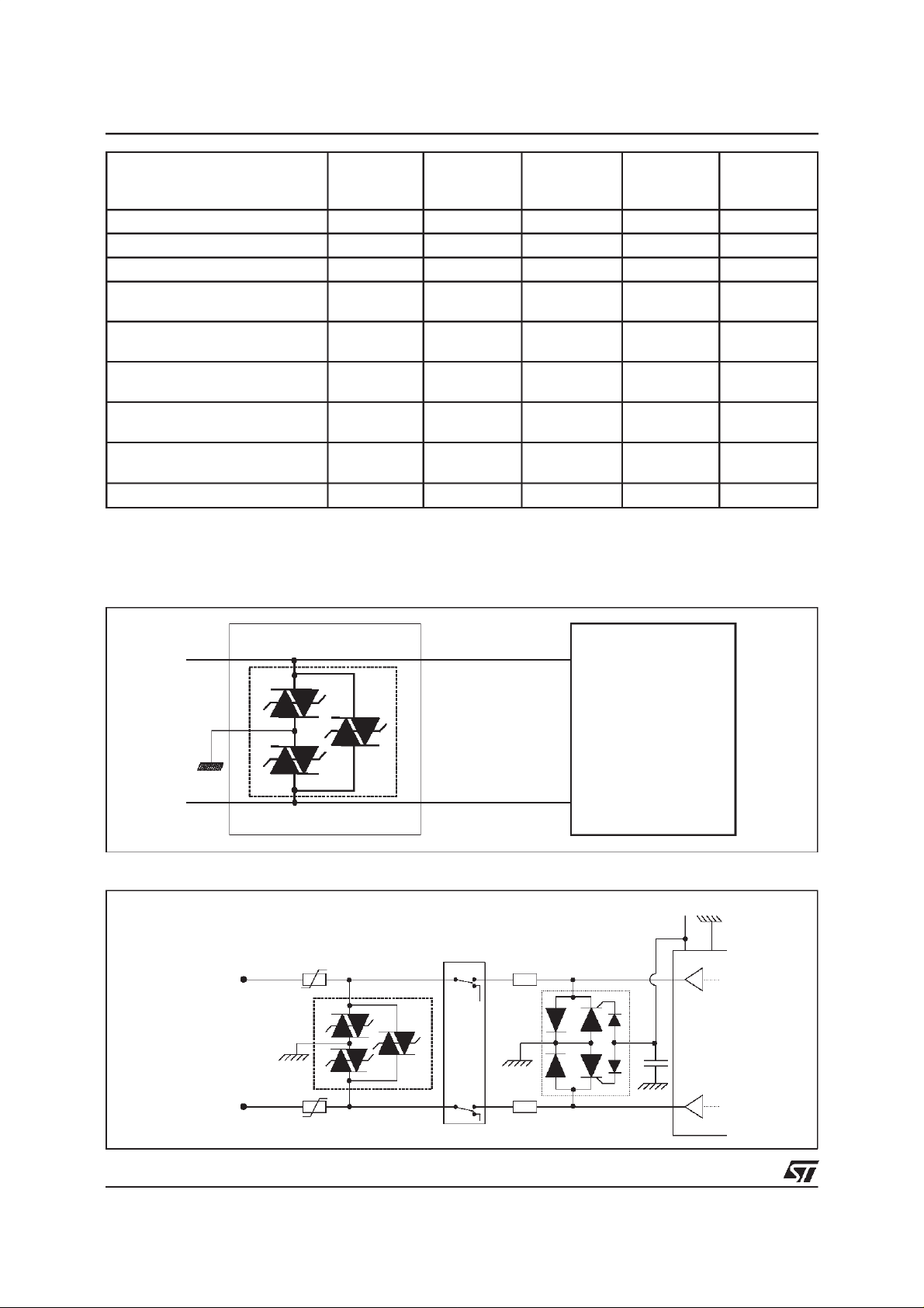
TYPICALAPPLICATION
Primaryprotection module
(Ω)
-
-
-
-
-
-
TLPxxM/G/G-1
Main Distribution Frame
Analog line card protection
LINE A
TLPxxM/G/G-1
PTC
RING
RELAY
LCP1511D
Analog
Line
Card
220
-Vbat
SLIC
nF
2/14
LINE B
PTC
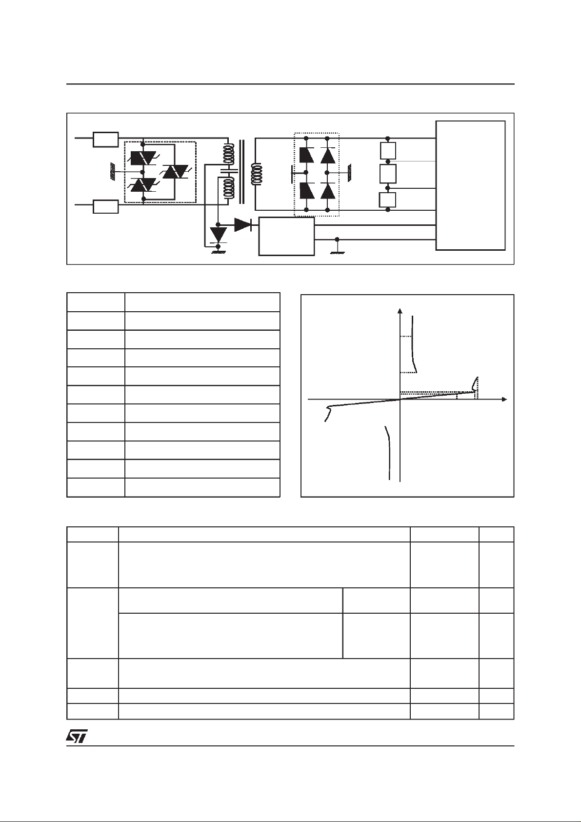
TYPICALAPPLICATION
ISDN: U interfaceprotection
TLPxxM/G/G-1
TLPxxM/G/G-1
PARAMETER MEASUREMENT INFORMATION
Symbol Description
I
PP
I
TSM
I
I
RM
I
V
R
H
BR
Peak pulse current
Maximumpeak on-statecurrent
Leakagecurrent
Leakagecurrent
Holdingcurrent
Breakdownvoltage
1/2 DA108S1
+5V
Power
Feeder
R3
R4
R5
IRM
IPP
IR
Internal
circuitry
IH
VRM
VRVBO
V
R
V
RM
V
BO
Continuousreversevoltage
Maximumstand-off voltage
Breakovervoltage
C Capacitance
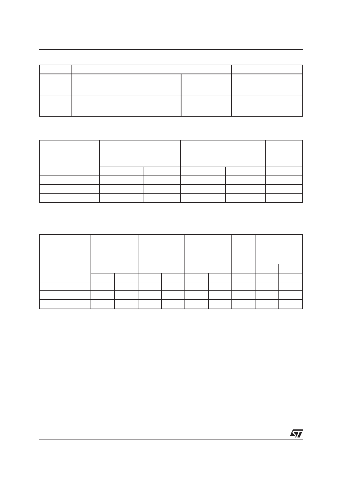
ABSOLUTE MAXIMUMRATINGS
(T
amb
=25°C)
Symbol Parameter Value Unit
I
PP
I
TSM
Peakpulse current(longitudinal& transversalmode) :
10/1000µs (opencircuitvoltagewaveform1 kV 10/1000µs)
8/20µs (opencircuit voltagewaveform4 kV 1.2/50µs)
2/10µs (opencircuit voltage waveform2.5kV 2/10 µs)
Mainspowerinduction
t = 200ms 0.7 A
100
250
500
VRMS= 300V,R = 600Ω
Mainspowercontact
V
= 220V,R =10Ω (Fail-Safethreshold) t = 200 ms
RMS
=220V, R = 600
V
RMS
T
stg
Storagetemperaturerange - 55 to+ 150 °C
Ω
t = 15 mn 0.42 A
31 A
Tj Maximumoperatingjunctiontemperature 150 °C
T
L
T
OP
Maximumleadtemperaturefor solderingduring10 s 260 °C
Operatingtemperaturerange - 40 to+ 85 °C
A
A
A
3/14
TLPxxM/G/G-1
THERMALRESISTANCE
Symbol Parameter Value Unit
Rth (j-c) Junctionto case TLPxxM
TLPxxG
TLPxxG-1
Rth (j-a) Junctionto ambient TLPxxM
TLPxxG
TLPxxG-1
seetable page 14
seetable page 14
seetable page 14
1.0
1.0
1.0
C/W
°
°C/W
ELECTRICAL CHARACTERISTICS BETWEEN TIP AND RING
@V
I
Type
RM
max. max. typ.
RM
(T
amb
IR@V
=25°C)
R
note
µAVµAVpF
TLP140M/G/G-1
TLP200M/G/G-1
TLP270M/G/G-1
Note : VR= 50 V bias, V
= 1V, F = 1 MHz.
RMS
ELECTRICALCHARACTERISTICS BETWEEN TIP AND GND, RINGAND GND(T
I
RM
Type
max.
5 120 50 140 35
5 180 50 200 35
5 230 50 270 35
=25°C)
amb
@V
RM
IR@V
R
V
BO
I
BO
@
IH C @ V
max. max. max. min. typ.
note 1 note 2 note 3 note 4 note 5
µAVµAV VmAmApFpF
TLP140M/G/G-1
5 120 50 140 200 500 150 110 40
TLP200M/G/G-1 5 180 50 200 290 500 150 110 40
TLP270M/G/G-1
Note 1: IRmeasured at VRguaranteesV
Note 2: Measured at 50 Hz.
Note 3: See functional holdingcurrent test circuit.
Note 4: VR= 0V bias, V
Note 5: VR= 50V bias, V
5 230 50 270 400 500 150 110 40
BR min>VR
= 1V, F = 1 MHz.
RMS
= 1V, F = 1 MHz (TIPor RING (-) / GND (+)).
RMS
.
C
R
4/14
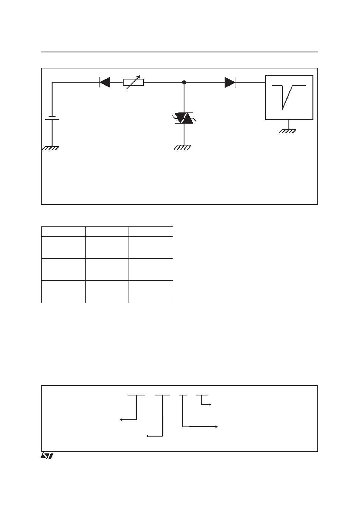
FUNCTIONAL HOLDING CURRENT (IH) TEST CIRCUIT: GO-NO GOTEST
R
V
BAT
=
-48V
D.U.T .
TLPxxM/G/G-1
-V
P
Surge
generator
This is a GO-NOGO test which allowsto confirmthe holdingcurrent (IH)level in a functionaltest circuit.
TESTPROCEDURE:
- Adjust the currentlevelat theI
- FiretheD.U.T. with a surgecurrent: I
value by short circuitingthe D.U.T.
H
=10A, 10/1000µs.
PP
- The D.U.T.will come back to the off-statewithin a durationof 50ms max.
MARKING
Package Types Marking
PowerSO-10 TLP140M
TLP200M
TLP270M
2
PAK TLP140G
D
TLP200G
TLP270G
2
PAK TLP140G-1
I
TLP200G-1
TLP270G-1
TLP140M
TLP200M
TLP270M
TLP140G
TLP200G
TLP270G
TLP140G
TLP200G
TLP270G
ORDERCODE
TripolarLine Protection
TPL 270 M-TR
BreakdownVoltage
Packaging:
-TR=tapeandreelonlyfor”M”versi on(600pcs)
= tube(50 pcs)
Package:
M: PowerSO10
2
PAK
G:D
2
G-1: I
PAK
5/14
 Loading...