


SAMSUNG SMARTCAM
User Manual

 0678 !
SNH-P6410BN

Samsung SmartCam
User Manual
Copyright
©2014 Samsung Techwin Co., Ltd. All rights reserved.
Trademark


 is the registered logo of Samsung Techwin Co., Ltd. The name of this product is the registered trademark of Samsung Techwin Co., Ltd. Other trademarks mentioned in this manual are the registered trademark of their respective company.
Restriction
Samsung Techwin Co., Ltd shall reserve the copyright of this document. Under no circumstances, this document shall be reproduced, distributed or changed, partially or wholly, without formal authorization of Samsung Techwin.
Disclaimer
Samsung Techwin makes the best to verify the integrity and correctness of the contents in this document, but no formal guarantee shall be provided. Use of this document
and the subsequent results shall be entirely on the user’s own responsibility. Samsung Techwin reserves the right to change the contents of this document without prior notice.
SPECIFY SERVICE INSTRUCTIONS AND WARRANTY TERMS
This device complies with Part 15 of the FCC Rules.
Operation is subject to the following two conditions: (1) this device may not cause harmful interference, and (2) this device must accept any interference received, including interference that may cause undesired operation.
FCC NOTE:
THE MANUFACTURER IS NOT RESPONSIBLE FOR ANY RADIO OR TV INTERFERENCE CAUSED BY UNAUTHORIZED MODIFICATIONS TO THIS EQUIPMENT.
SUCH MODIFICATIONS COULD VOID THE USER'S AUTHORITY TO OPERATE THE EQUIPMENT.
Operational Description
The operational description shall fulfil the requirements of Rule Part 2.1033(b)(4). The rule part requires, "A brief description of the circuit functions of the device along with a statement describing how the device operates. This statement should contain a description of the ground system and antenna, if any, used with the device".
The above requirement has been further interpreted by the FCC to mean that the description shall:
a.be an operational or technical description of how the device operates, is modulated and meets requirements;
b.describe the EUT completely. What is it (in plain English as well as technical terms)? Give a clear, concise functional description of device operation.
c.always describe the signal, such as modulation type, pulse repetition rate, signal type and information being sent. Describe all modulation types and all data rates.
Instructions & Warranty
The manufacturer is not responsible for any loss or radio/TV interference caused by unauthorized modification of the product.
Such modification will void the warranty of the product as well as the user’s right of use.
WARNING
•The product must be assembled and installed by an adult.
•Before using, read all instructions on this manual thoroughly and follow operational instructions, warnings on this manual and printed on the product.
•To avoid entangled power cord, do not place it around the baby bed or other infant furniture. Keep this product and its power cord out of children’s reach.

•Especially, the power cord should be installed carefully while keeping it out of children’s reach.
•Never use the product near bath tub, sink, washing machine and in wet basement to avoid moisture.
•The product is designed for indoor use.
•The product is not designed for medical monitoring, and requires a grown-up’s protective supervision on its use.
•To avoid overheating of the product, do not expose the product to direct sunlight; do not install or use near a heat source such as heater, radiator, cooking devices (ex: electric stove or oven) and other warming devices (ex: audio amplifier, TV, etc.).
•Make sure to keep ventilated while using the product.
Avoid pillar or furniture that may block ventilation, when installing the product.
•Make sure to use the power adaptor provided. If used with unidentified adaptor, it may damage the product. The power adaptor must be used with regular household electric supply.
•Avoid sharp, pointed objects around the adaptor’s cable, not to damage the cable.
•Be warned and never hold the cable’s stripped part when connecting / disconnecting the adaptor to/from the wall outlet.
•To avoid entangled cable lines, avoid using cable extension for adaptor’s power cord.
•The product’s servicing is allowed only to authorized Samsung Techwin’s service personnel.
•When using the product for children’s care, be careful to keep the product out of children’s reach.
•The product partially contains component which might cause respiration difficulty. Accessories and small parts of the product should be stored keeping out of children’s reach.
•The product is not designed to replace responsibility of human supervision on children.
•The product is not equipped with device of immediate notification to adult with accidental/sudden children‘s move; it requires periodic checks and human supervision.
•This appliance and its antenna must not be collocated or operation in conjunction with any other antenna or transmitter. A minimum separation distance of 20 cm must be maintained between the antenna and the person for this appliance to satisfy the RF exposure requirements.
Contents
GETTING STARTED
Features ……………………………………………………… 4 What’s Included ……………………………………………… 5 Part names and functions …………………………………… 6
INSTALLATION & NETWORK CONNECTION
Installation …………………………………………………… 8 Network Connection and Settings…………………………… 12
MONITORING
Registration …………………………………………………… 14 Live Video …………………………………………………… 19 Setup ………………………………………………………… 21 Event Alarm ………………………………………………… 30 Playback ……………………………………………………… 30 Information …………………………………………………… 31
APPENDIX
Specifications ………………………………………………… 33 Troubleshooting ……………………………………………… 37

GETTING STARTED01
Features |
4 |
What’s Included |
5 |
Part names and functions |
6 |
Power Supply |
7 |
Connecting the Ferrite Core to the power supply |
7 |
adaptor |
|
Network connection |
7 |
Features
•Easy to install
-Simply visit the home page (www.samsungsmartcam.com) and download and install the program without a separate installer program.
•Remote monitoring
-Whenever and wherever if you are in the Internet enabled environment, remote monitoring is ready for you.
-PC, laptop or smart phone can be used for monitoring.
•Real-time alarm
-When a motion and sound are detected, your smartphone will generate real time alarms.
•Cloud Storage
-Users can automatically upload event photos to their Picasa accounts.
-Anytime anywhere you can enjoy the video and images stored in the cloud storage.
•Saving in SD card
-When an event occurs, the user can save the video in their SD card.
•Two-way Audio
-With the built-in speakers and microphone, you can make Two-way communications.
However, it is available only with the smart phone. (Not applicable to the PC or laptop computer.)
•SNS (Social Networking Service) Alarm supported
-Provide event alerts (messages, photos) through Picasa or Twitter.
-Share your photos with your friends.
•IR LED
-At low illumination levels, you can use an IR LED for monitoring purposes.
4 · English

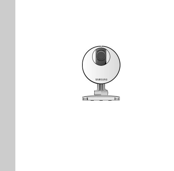
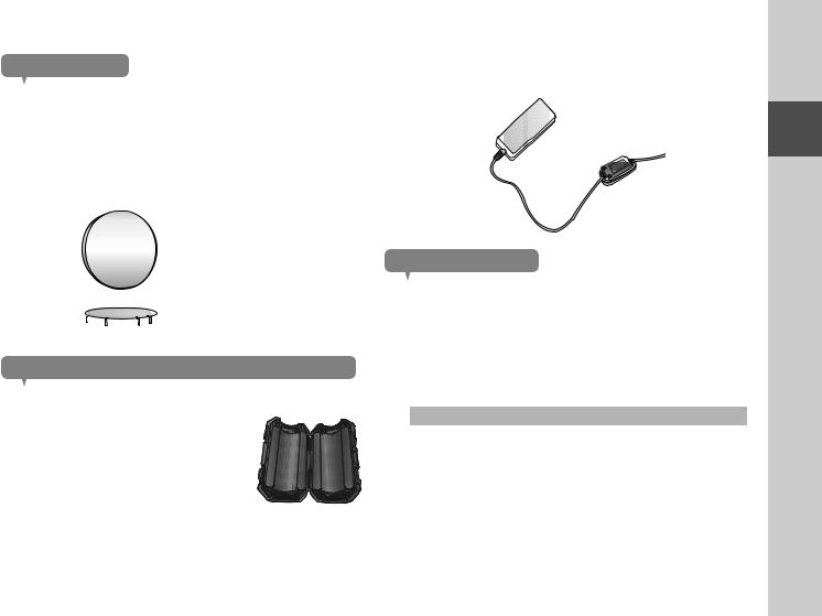
What’s Included
Check for components when opening the product package.
Camera & Bracket body |
Power Adaptor |
Network Cable |
Quick Start Guide |
Warranty Card |
GPL Lisence |
Double Sided Tape |
Tapping screw |
Plastic anchor |
Ferrite Core |
n ` Please save the packaging. You will need the serial number later to register the camera.
01
Started Getting
5
Part names and functions
Power / Wi-Fi status LED
Built-in IR LEDs for night vision
Camera lens
Luminance Sensor 
Detects light levels where the camera is placed. Night vision mode changes according to detection result.
Speakers
Generate audio output from your smart phone.
SD card insertion hole
RESET |
SAMSUNG SMART CAM |
|
|
|
MODEL : SNH-P6410BN |
DC 5.0V |
2.2A |
|
Aug |
2013 S/N : XXXXXXXXXXXXXXX |
NETWORK |
|
M/C |
: SNH-P6410BN/EX |
|
|
MAC ADDRESS : XX-XX-XX-XX-XX-XX |
|
||
SAMSUNG TECHWIN CO., LTD. |
MADE BY SAMSUNG IN CHINA |
Wi-Fi Direct button
Create a Wi-Fi connection for your camera and smart phone.
Reset button
Resets the camera settings to the default.
Press and hold for about 10 seconds to reboot the system.
Network port
Used for wireless connection.
DC 5V Power Input
Audio out
Generates audio output to external devices.
Built-in Mic
6 · English
Power Supply
Plug-in the camera power adapter to the wall outlet and connect the camera as shown.
n ` |
Make sure to use the provided power adaptor. If you use an adaptor other than the |
|
power supply adaptor provided in our package, the product may not operate properly. |
` It will take about 1min for the camera to boot-up completely. |
|
` |
When the boot-up is complete, the power LED color will change from red to blue. |
|
SAMSUNG SMART CAM |
Connecting the Ferrite Core to the power supply adaptor
Ferrite Core can stabilize the power supply.
1.Open the Ferrite Core included in the package.
2.As shown in the figure, place the ferrite core about 10 cm away from the warning tag of your adaptor and roll it up to show the two lines of power supply outside. Then close the ferrite core.
Network connection
Connect the provided network cable to the camera’s network terminal.
For further details on network configuration, refer to “Network Connection and Settings”. (Page 12)
LED status
LED indicator shows operational status with colors.
Refer to table below for detailed meaning of the LED indicator.
Color |
Status |
Red |
Booting up |
Red Blinking |
Booting completed / Establishing network connection |
Blue Blinking |
Connecting to the network. |
Blue |
Local connection established |
Green |
Connection to server completed / Normal operation |
Magenta |
Updating firmware |
01
Started Getting
7

INSTALLATION 02&
NETWORK CONNECTION
Installation
Precautions
1.Install the camera in a place where the Wi-Fi signal can be reached and without interference.
2.Keep it away from humidity such as around the humidifier.
3.Keep it away from direct sunlight, strong light or dust; install it in a place with clear view.
4.Do not install it in a place where there are a lot of obstacles.
5.Keep the lens clean at all times. Wipe off the dust with a soft cloth.
Installation |
8 |
Precautions |
8 |
Wall Mounting Using Double-sided adhesive tape |
9 |
Wall Mounting with Screws |
11 |
Desktop mounting |
12 |
Network Connection and Settings |
12 |
Precautions |
12 |
Connecting via network cable |
13 |
Wi-Fi connection setting |
13 |
8 · English

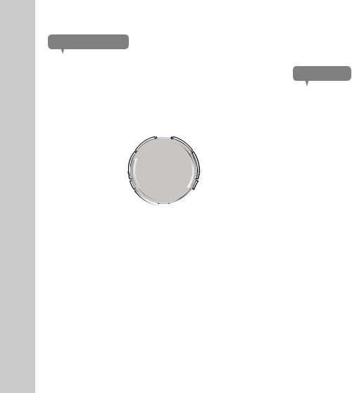
Wall Mounting Using Double-sided adhesive tape
Separating the wall-mount bracket
1.While pulling the button in the back of the bracket, press the bottom of the opposite side of the button to remove the bracket wall.
KRO
CAM
SMART
SAMSUNG
Assembling
1. Take out the wall fixing tape.
2. Remove the rectangular protective film from the adhesive tape and attach it to the bottom of the wall-mount bracket.
3.Hold the handle for the wall fixing tape, remove the release paper to attach the tape.
n` The tape will lose adhesiveness if used once, do not re-use.
`Before attaching tape, clean dust / water / oil off the wall-mount bracket’s adhesive spot for better result.
9
02
Connection Network & Installation
4.Firmly insert the bracket from the opposite side of the button until you hear a clicking sound.
5.Connect the adaptor’s plug to the power terminal on the camera’s rear side.
n ` When done, remove the protective film from the lens.
Adjusting the Angle
1.Adjust the camera’s shooting angle as appropriate.
n |
` Do not put excessive force. Otherwise, it may |
|
||
|
cause damage to the camera. |
|
||
|
|
|
|
|
|
|
|
|
|
|
|
|
|
|
|
|
|
|
|
|
|
|
|
|
|
|
|
|
|
|
|
|
|
|
|
|
|
|
|
|
|
|
|
|
|
|
|
|
|
|
|
|
|
|
|
|
|
|
|
|
|
|
|
|
2.Open the cap in the area marked in the figure and use a driver to turn the screw clockwise to fasten and fix the recording angle.
3.If you turn the screw counterclockwise, it will be loosened and you can adjust the recording angle then.
10 · English
Wall Mounting with Screws
n |
` For more information about step of Separating the wall-mount bracket, refer to “Wall |
|
Mounting Using Double-sided adhesive tape”. |
Assembling
1.Take out screws (M3xL20), and anchors (Φ5x25mm).
2.On a wooden wall, use screws to fix the
wall-mount bracket as shown in the figure. Using a driver on the wall to attach it to, fasten three screws in the three holes.
3.If fixing on a concrete wall, use screws and anchors to fix wall-mount bracket. First, mark on the wall as shown in the figure below.
4.Use drill bit of 5mm diameter and drill on the marked positions, drill to have 3 cm depth holes. Clean the holes after drilling.
J ` Be careful not to get injured while drilling.
5.Insert an anchor for each hole. Fully insert anchors by hammering lightly the anchor head with a hammer/rubber hammer.
6.Using a driver on the wall to attach it to, fasten three screws in the three holes.
n |
` For further steps, refer to the instructions for |
|
“Wall Mounting Using Double-sided |
|
adhesive tape”. |
02
11 |
Connection Network & Installation |
Desktop mounting
n |
` For more information about step of Separating the wall-mount bracket, refer to “Wall |
|
Mounting Using Double-sided adhesive tape”. |
Assembling
1.Firmly insert the bracket from the opposite side of the button until you hear a clicking sound.
2.Using the groove on the bracket wall, rotate the bracket in the desired direction.
3.Connect the adaptor’s plug to the power terminal on the camera’s rear side.
SAMSUNG SMART CAM
Network Connection and Settings
Precautions
•The wireless network access may fail, depending on the communications environment.
•For details about the network settings and password, contact your network administrator or service provider.
•For a specific Internet service requiring user authentication, you may not access the service. If this is the case, contact the service provider.
•Do not access the unauthorized network.
•The farther the distance from the Wireless Access Point, the longer time the network connection may take.
•If you fail to access the selected wireless network, try a different Wireless Access Point to make access.
•For more information about the router or the wireless connection, refer to the documentation of the router or contact the router manufacturer.
•If the camera is connected to a multiple-Wireless Access Point network environment, some video packets may be lost, depending on the network traffic load.
•According to the network policy (blocking UDP) of the service provider, the video transmission can be limited to 7 minutes.
For more details, refer to the descriptions on page 21, <Relay Mode>.
•In addition to the above two situations, you may encounter a network delay or interruption due to the network conditions.
•Some hubs can have compatibility issues.
12 · English
 Loading...