


NETWORK VIDEO DECODER
User Manual
SPD-151

Network Video Decoder
User Manual
Copyright
©2019Hanwha TechwinCo.,Ltd.Allrightsreserved.

overview
Important Safety Instructions Standards Approvals
Read these operating instructions carefully before using the unit.
Follow all the safety instructions listed below.
Keep these operating instructions handy for future reference.
1)Read these instructions.
2)Keep these instructions.
3)Heed all warnings.
4)Follow all instructions.
5)Do not use this apparatus near water.
6)Clean the contaminated area on the product surface with a soft, dry cloth or a damp cloth.
(Do not use a detergent or cosmetic products that contain alcohol, solvents or surfactants or oil constituents as they may deform or cause damage to the product.)
7)Do not block any ventilation openings, Install in accordance with the manufacturer's instructions.
8)Do not install near any heat sources such as radiators, heat registers, stoves, or other apparatus (including amplifiers) that produce heat.
9)Do not defeat the safety purpose of the polarized or groundingtype plug. A polarized plug has two blades with one wider than the other. A grounding type plug has two blades and a third grounding prong. The wide blade or the third prong are provided for your safety. if the provided plug does not fit into your outlet, consult an electrician for replacement of the obsolete outlet.
10)Protect the power cord from being walked on or pinched particularly at plugs, convenience receptacles, and the point where they exit from the apparatus.
11)Only use attachments/accessories specified by the manufacturer.
12)Use only with the cart, stand, tripod, bracket, or table specified by the manufacturer, or sold with the apparatus. When a cart is used, use caution when moving the cart/ apparatus combination to avoid injury from tip-over.
13) Unplug this apparatus during lightning storms or when unused for long periods of time.
14)Refer all servicing to qualified service personnel. Servicing is required when the apparatus has been damaged in any way, such as power-supply cord or plug is
damaged, liquid has been spilled or objects have fallen into the apparatus, the apparatus has been exposed to rain or moisture, does not operate normally, or has been dropped.
15)This product is intended to be supplied by Listed Power Unit marked "Class 2" or "LPS" and rated 12 Vdc, Min. 1.8 A.
16)The wired LAN hub providing power over the Ethernet (PoE) in accordance with IEEE 802-3af shall be a UL Listed device with the output evaluated as a Limited Power Source as defined in UL60950-1.
17)Associated Ethernet wiring shall be limited to inside the building.
JJ `` Any changes or modifications in construction of this device which are not expressly approved by the party responsible for compliance could void the user's authority to operate the equipment.
MM`` This device complies with part 15 of the FCC Rules. Operation is subject to the following two conditions: (1) This device may not cause harmful interference, and (2) this device must accept any interference received, including interference that may cause undesired operation.
`` This equipment has been tested and found to comply with the limits for a Class A digital device, pursuant to part 15 of the FCC Rules. These limits are designed to provide reasonable protection against harmful interference when the equipment is operated in a commercial environment.
This equipment generates, uses, and can radiate radio frequency energy and, if not installed and used in accordance with the instruction manual, may cause harmful interference to radio communications. Operation of this equipment in a residential area is likely to cause harmful interference in which case the user will be required to correct the interference at his own expense.
overview●
English _3

overview
Before Start
This manual provides operational information necessary for using the product and contains a description about each component part and its function as well as menu or network settings.
You have to keep in mind the following notices :
••Hanwha Techwin retains the copyright on this manual.
••This manual cannot be copied without Hanwha Techwin's prior written approval.
••We are not liable for any or all losses to the product incurred by your use of non-standard product or violation of instructions mentioned in this manual.
••Prior to opening the case, please consult a qualified technician first. Whenever this is needed power must be removed from the unit.
Warning
Battery
It is essential that when changing the battery in the unit, the replacement battery must be of the same type otherwise there may be a possibility of an explosion.
The following are the specifications of the battery you are using now.
••Normal voltage : 3V
••Normal capacity : 210mAh
••Continuous standard load : 0.4mA
••Operating temperature : -20°C ~ +60°C (-4°F ~ +140°F)
Caution
••Connect the power cord into a grounded outlet.
••The Mains plug is used as a disconnect device and shall stay readily operable at any time.
••Batteries shall not be exposed to excessive heat such as sunshine, fire or the like.
••Risk of Explosion if Battery is replaced by an Incorrect Type. Dispose of Used Batteries According to the Instructions.
Operating Temperature
The guaranteed operating temperature range of this product is 0°C ~ 40°C (32°F ~ 104°F).
This product may not work properly if you run right after a long period of storage at a temperature below the guaranteed one.
Prior to using a device that has been stored for a long period in low temperatures, allow the product to stand at room temperature for a period.
Security Precautions
The initial administrator ID is “admin” and the password should be set when logging in for the first time. Please change your password every three months to safely protect personal information and to prevent the damage of the information theft.
Please, take note that it’s a user’s responsibility for the security and any other problems caused by mismanaging a password.
4_ overview

Contents
overview |
3 |
Important Safety Instructions |
3 |
4 |
Before Start |
5 |
Contents |
|
6 |
Features |
|
7 |
Part Names and Functions (Front) |
|
|
7 |
Part Names and Functions (Rear) |
connecting with other device |
8 |
Connecting to an external device |
8 |
8 |
Connecting the USB |
8 |
Connect Ethernet |
|
8 |
Connect power |
|
9 |
Connecting ground wire |
|
|
9 |
Connecting the Network |
network connection and setup |
10 |
Using Device Manager |
10 |
10 |
How to connect to a network decoder |
11 |
Login |
video wall |
12 Video wall settings |
12 |
|
layout |
14 |
layout |
14 |
|
|
menu setup |
19 |
System Setup |
19 |
22 |
Network Configuration |
video wall configuration guide |
24 |
video wall configuration guide |
24 |
|
|
appendix |
27 |
Product Overview |
26 |
26 |
Product Specification |
27 |
Default Setting |
|
28 |
Troubleshooting |
|
29 |
Open Source License Report on the Product |
overview●
English _5

overview
Features
This product can monitor the video and audio from network cameras. Provides an environment in which you can set this product on your PC.
••Convenient Web UIs
••4K camera resolution support
••Outputs a 4K high definition image using HDMI
••Supports ONVIF Profile S standard and RTP / RTSP protocols
••49 channels simultaneous output (HDMI: 32 channels, VGA: 16 channels, CVBS: 1 channel)
••Various user defined layout support
••SSM VM sync
Package Contents
Please unwrap the product, and place the product on a flat place or in the place to be installed. Please check the following contents are included in addition to the main unit.
|
|
|
LINK |
ACT |
HDMI |
VGA |
VIDEO OUT |
NETWORK DC12V |
|
Decoder |
Quick Guide |
Terminal block |
Taping screw |
Plastic Anchor |
6_ overview
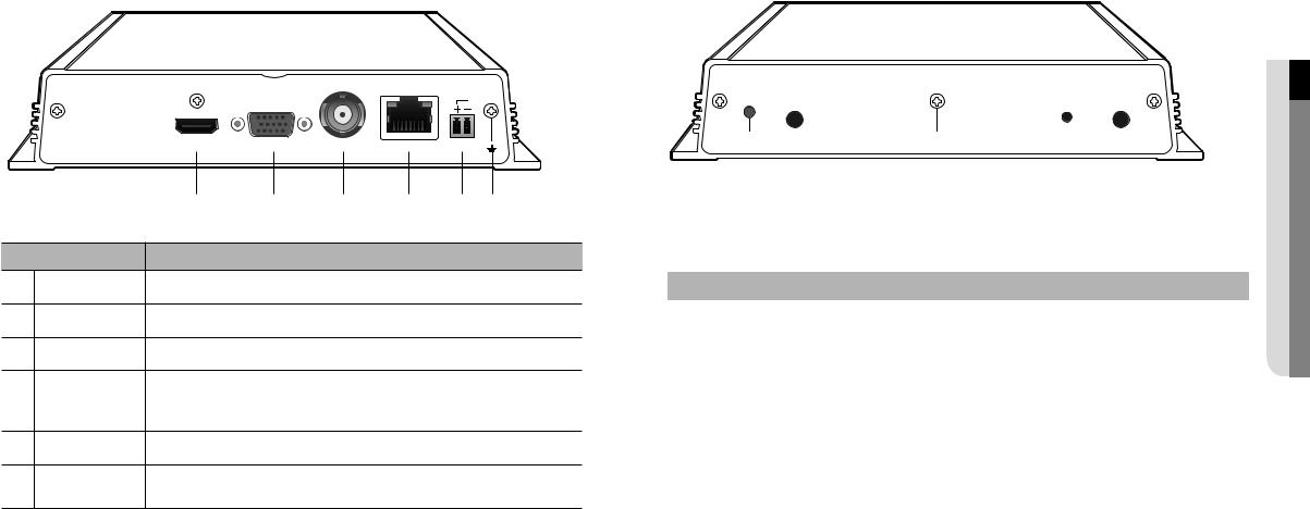
Part Names and Functions (Front) |
|
Part Names and Functions (Rear) |
|
|
|
|
LINK |
ACT |
|
|
HDMI |
VGA |
VIDEO OUT |
NETWORK |
DC12V |
|
|
a |
b |
c |
d |
|
e f |
Part Names |
|
|
Functions |
|
|
|
a HDMI |
HDMI connector port. |
|
|
|
|
|
b VGA |
VGA Video Signal Output Port. |
|
|
|
|
|
c VIDEO OUT |
A CVBS video display terminal. |
|
|
|
|
|
d NETWORK |
This is a terminal to connect to Ethernet cable. |
|
|
|
||
`` Power input can be provided using PoE. (Please see “Product specifications” for the PoE |
||||||
|
power specifications.) |
|
|
|
|
|
e DC12V |
This is a terminal to connect a designated power supply. |
|
|
|||
f Ground connection |
Terminal to connect a separate ground cable. |
|
|
|
||
` |
|
|
|
|
|
|
|
` Add a ground cable to support the safe use of the device. |
|
|
|||
overview●
POWER CONSOLE USB  USB RESET AUDIO OUT
|
|
|
|
|
|
|
|
|
|
|
|
|
|
|
|
a |
b |
|
d |
|
e |
f |
|||||||
|
|
|
|
|
|
|
c |
|
|
|
|
|
|
|
|
|
|
|
|
|
|
|
|
|
|
|
|||
|
|
|
|
|
|
|
|
|
|
|
|
|
|
|
|
Part Names |
|
|
|
|
|
|
|
Functions |
|
|
|
|
|
a |
POWER |
|
|
It displays the power ON/OFF status using an LED. |
|
|
|
|
||||||
b |
CONSOLE |
|
|
[CONSOLE] is a terminal for later customer service. |
|
|
|
|
||||||
c |
USB |
|
|
[USB] is a terminal for later customer service. |
|
|
|
|
||||||
d |
Ground connection |
Terminal to connect a separate ground cable. |
|
|
|
|
||||||||
` |
|
|
|
|
|
|
|
|
|
|||||
|
|
|
|
|
` Add a ground cable to support the safe use of the device. |
|
|
|||||||
|
RESET |
|
|
This button can be used to initialize the device if you have forgotten your password. |
||||||||||
e |
|
|
If you press and hold the button for about 10 seconds, the password initialization pop-up window |
|||||||||||
|
|
|
|
|
will open, prompting you to reset the password. |
|
|
|
|
|||||
f |
AUDIO OUT |
|
|
This is a terminal for voice signal output (3.5 π). |
|
|
|
|
||||||
English _7

connecting with other device
connectIng to an externaL devIce |
connect ethernet |
|
|
|
Connect the Ethernet cable to connect it to a local network or the internet. |
Network |
It can be connected without a power adapter by supplying power separately from the PoE switch. |
|
` Please see "Product specifications" for the PoE power specifications. (Page 28) |
||
Microphone |
|
LINK |
ACT |
Camera |
VGA |
VIDEO OUT |
DC12V |
HDMI |
|
|
|
|
|
|
|
|
Ethernet |
Power |
Grounding Cable |
|
|
|
DEO |
|
|
|
|
|
||
|
|
|
|
connect poWer |
|
|
|
|||
|
|
|
|
|
|
|
|
|||
|
|
|
|
|
When using a normal Ethernet cable, connect to the power adapter for power supply. |
|||||
|
|
|
|
|
Connect the (+, -) wires of the power adapter to the power input terminal of the network video decoder using a |
|||||
|
|
|
|
|
screwdriver. |
|
|
|
|
|
|
|
HDMI OUT |
VGA OUT |
VIDEO OUT |
J |
` When using PoE and DC 12V power simultaneously, the device will be operated with the external power (DC 12V). |
||||
|
|
|
|
|
|
- |
If you use and connect a router with a PoE function, no external power is required. |
|||
|
J |
` Unrated or improper power source may cause damage to the system. Ensure that you use only the rated power source |
|
- |
PoE should be compatible with IEEE 802.3af. |
|
|
|||
|
|
before pressing the POWER button. |
|
|
|
` As DC 12V has polarity, be careful when you connect it. |
|
|
||
connectIng the uSB |
|
|
|
` When connecting external devices, you must first turn off the power to the devices. |
|
|||||
|
|
|
` Connect the set and adpater power cable first, and then plug it into a wall socket rated 220V. |
|||||||
|
|
|
|
|
|
|||||
1. On the front of the product, there is a USB port. |
|
|
|
` Do not extend the adapter output cable. |
|
|
|
|||
|
|
|
` If you need to extend the power cable, contact the service center. |
|
|
|||||
2. You can connect your USB memory through the USB port. |
|
|
|
|
|
|||||
3. |
operating the system. |
|
|
power cable Specification for each model |
|
|
||||
The product supports hot plugging function that enables connecting/disconnecting USB devices while in |
|
|
|
|
|
|
||||
|
J ` Some USB devices may fail to function properly due to compatibility issue, please check the device before using. |
|
|
Input power |
Wire Type (AWG) |
|
Cable Length (Max.) |
|||
|
|
|
DC 12V |
#18 |
|
19m |
||||
|
|
` Only USB storage devices that comply with the standards (having a metal cover) are guaranteed for data transfer. |
|
|
#16 |
|
30m |
|||
|
|
` A worn-out USB connector pin might deteriorate the delivery of USB signal. |
|
|
|
|
|
|||
|
|
|
|
|
|
|
|
|
||
8_ connecting with other device
Connecting ground wire
Connect the ground wire to the FG screw at the right side of the power input terminal using a screwdriver.
JJ `` Grounding protects the product from being damaged by lightning. `` When connecting, be sure to turn off the power to devices.
Recommended specifications for ground wire
•Length: Maximum 3M
•Thickness: 18AWG or thicker
Ex) UL1007 AWG18/16, UL1015 AWG18/16/14/12, UL2468 AWG18/16/14
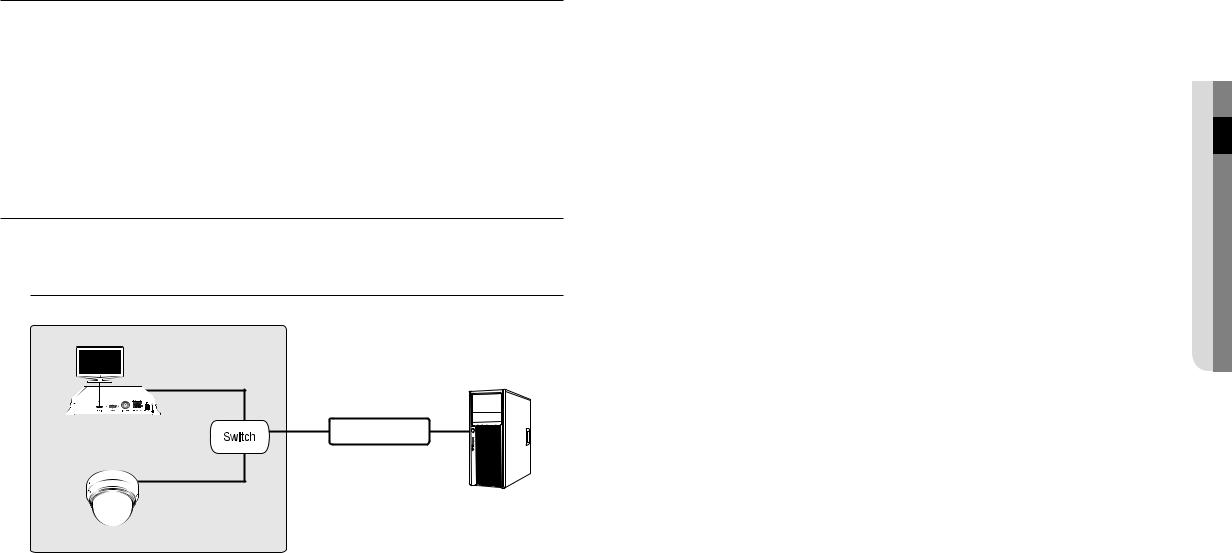
Connecting the Network
MM`` For more information about network connection, refer to "Network Configuration". (Page 24)
How to install the network video decoder
Network Video Decoder |
Network Camera
 INTERNET
DDNS Server
(Data Center)
device other with connecting●
English _9
network connection and setup
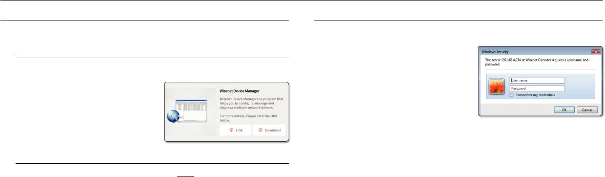
uSIng devIce manager
Wisenet Device Manager allows you to set up and run your network and easily check the network status.
Installing device manager
To download the Device Manager program, visit the official website of Hanwha Techwin (http://www.hanwhasecurity.com).
1.On the website, go to <technical guides> - <online tool> to download Device Manager.
2.Download and install the Device Manager program.
•Once installed, the program will run automatically.
•For the details of how to use Device Manager, see <help> in the main menu.
Watch the video guide of device manager
On the Download screen of the Device Manager program, click <  >.
>.
You can learn about the following in the video.
•Device Manager intro
•Product login and password change
•Use project
•Change product IP
•Check product information report
•Save and restore product settings
•Camera video settings
•Camera setup settings
•Download/update firmware
hoW to connect to a netWork decoder
normally, you would
1.Launch the Internet browser.
2.Enter the IP address of the network decoder in the address bar.
ex)
•IP address (IPv4) : 192.168.1.200 http://192.168.1.200
-the Login dialog should appear.
•IP address (IPv6) : 2001:230:abcd: ffff:0000:0000:ffff:1111 http://[2001:230:abcd:ffff:0 000:0000:ffff:1111]
-The login dialog should appear.
If the http port is other than 80
1.Launch the Internet browser.
2.Enter the IP address and HTTP port number of the network decoder in the address bar. ex) IP address : 192.168.1.200:HTTP Port number(8080)
http://192.168.1.200:8080
- The login dialog should appear.
10_ network connection and setup
LogIn
Your preferred language and a new password must be entered during your initial connection after purchase.
1.Select a language for the <Language> field.
2.In the <new p/W> field, enter a new password for the admin account.
3.In the <confirm p/W> field, reenter the new password for the admin account.
4.Click the [apply] button.
After the new password is successfully registered, a login screen appears.
M |
` For security, be sure to change the password in <User>- |
|
<Administrator> in the setting screen. |
|
` If you enter a user name and password, and then check the |
|
‘Save password in the password list’ checkbox, the user |
|
name and password will be automatically set for the next |
|
time you connect. |
J ` You cannot double-login with the "admin" account.
`It takes about five minutes after you disconnect from the "admin" account to access the user account.
System requirements
The minimum hardware and operating system requirements for running the web viewer are:
Name |
|
Minimum specifications |
|
- Supported OS: Windows : 7, 8.1, 10 |
|
|
|
Mac OS X : 10.10, 10.11, 10.12, 10.13 |
OS |
- Supported browsers: Google Chrome 63, Apple Safari 11 (Mac OS X only), MS Edge 41, |
|
|
MS Explorer 11 |
|
|
M |
It is recommended to use the browsers shown below for optimal use since this product |
|
|
is optimized for these. |
|
|
- Chrome 63 or higher, Safari 11 or higher |
Network |
10/100/1000 Ethernet NC |
|
Setup and connectIon netWork●
English _11
video wall
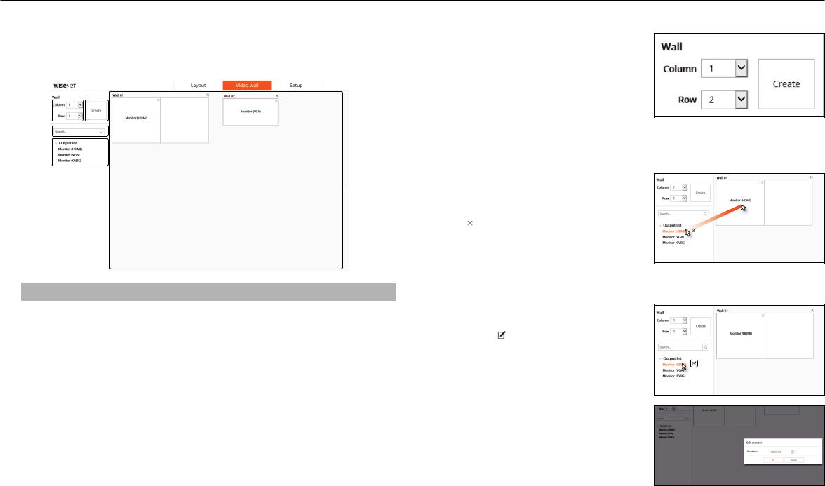
vIdeo WaLL SettIngS |
|
|
to set the video wall |
|||||||||
Sets the placement and layout of the connected monitors. |
|
|
1. |
Set the number of columns/rows in the upper left of |
||||||||
|
|
|
|
|
|
|
|
|
|
|
the video wall screen. |
|
|
|
|
a |
b |
2. |
Click the <create> button. |
||||||
|
|
|
|
|
|
|
|
3. |
The set video wall is registered on the right side of the |
|||
|
|
|
|
|
|
|
|
|
|
|
screen. |
|
|
|
|
|
|
|
|
|
|
|
M |
` If more than one monitor is assigned to the created video |
|
|
|
|
|
|
|
|
|
|
|
|||
c |
|
|
|
|
|
|
|
|
|
|
wall, you cannot enter the layout menu. |
|
|
|
|
|
|
|
|
|
|
|
|
||
|
|
|
|
|
|
|
|
|
|
|
||
d |
|
|
|
|
|
|
|
|
|
to assign a monitor |
||
|
|
|
|
|
|
|
|
|
||||
|
|
|
|
|
|
|
|
|
|
|||
|
|
|
|
|
|
|
|
1. |
From the list of connected monitors on the left side of |
|||
|
|
|
|
|
|
|
|
e |
the screen, choose the monitor you want to assign to |
|||
|
|
|
|
|
|
|
|
|
2. |
the video wall, then click and drag it there. |
||
|
|
|
|
|
|
|
|
To delete a monitor assigned to the video wall, click |
||||
|
|
|
|
|
|
|
|
|
|
|
[ |
] in the upper right corner of the assigned monitor. |
|
|
|
|
|
|
|
|
|
|
|
|
|
|
|
|
to edit a monitor |
|
|
Menu name |
Function description |
||
a |
Column/Row |
Sets the number of rows and columns of video walls to be created. |
1. |
When you select a monitor from the monitor list, the |
|
|
|
2. |
Edit Monitor button appears. |
b |
Video wall creation |
Creates as many video walls as you set. |
Click the [ ] button to set the resolution of the |
|
|
|
|
|
monitor. |
|
Search |
Searches the monitor from the output list. |
|
|
c |
• Resolutions : HDMI monitor can be set to 1280x1024, |
|||
|
|
|
|
720P, 1080P, 1440P, and 2160P. VGA monitor can be |
|
Output list |
|
|
|
d |
Displays a list of connected monitors. Connected monitors are enabled. |
|
set to 1280x1024, 720p, and 1080P. |
|
e |
Background |
The generated video walls are placed. |
|
|
12_ video wall
 Loading...