


NETWORK CAMERA
User Manual
SNP-3302/3302H/ 3371/3371H/3371TH

Network Camera
User Manual
Copyright
©2011 Samsung Techwin Co., Ltd. All rights reserved.
Trademark


 is the registered logo of Samsung Techwin Co., Ltd. The name of this product is the registered trademark of Samsung Techwin Co., Ltd.
Other trademarks mentioned in this manual are the registered trademark of their respective company.
Restriction
Samsung Techwin Co., Ltd shall reserve the copyright of this document. Under no circumstances, this document shall be reproduced, distributed or changed, partially or wholly, without formal authorization of Samsung Techwin.
Disclaimer
Samsung Techwin makes the best to verify the integrity and correctness of the contents in this document, but no formal guarantee shall be provided. Use of this document and the subsequent results shall be entirely on the user’s own responsibility. Samsung Techwin reserves the right to change the contents of this document without prior notice.
Warranty
If the product does not operate properly in normal conditions, please let us know. Samsung Techwin will resolve the problem for free of charge. The warranty period is 3 years. However, the followings are excluded:
•If the system behaves abnormally because you run a program irrelevant to the system operation.
•Deteriorated performance or natural worn-out in process of time
Design and specifications are subject to change without prior notice.
The default password can be exposed to a hacking thread so it is recommended to change the password after installing the product.
Note that the security and other related issues caused by the unchanged password shall be responsible for the user.

overview
IMPORTANT SAFETY INSTRUCTIONS
1. |
Read these instructions. |
|
|
2. |
Keep these instructions. |
|
|
3. |
Heed all warnings. |
● |
|
OVERVIEW |
|
||
4. |
Follow all instructions. |
|
|
|
|
||
5. |
Do not use this apparatus near water. |
|
|
6. |
Clean only with dry cloth. |
|
|
7. |
Do not block any ventilation openings, Install in accordance with the manufacturer’s |
|
|
8. |
instructions. |
|
|
Do not install near any heat sources such as radiators, heat registers, stoves, or other |
|
|
|
9. |
apparatus (including amplifiers) that produce heat. |
|
|
Do not defeat the safety purpose of the polarized or grounding-type plug. A polarized |
|
|
|
|
plug has two blades with one wider than the other. A grounding type plug has two |
|
|
|
blades and a third grounding prong. The wide blade or the third prong are provided for |
|
|
|
your safety. If the provided plug does not fit into your outlet, consult an electrician for |
|
|
|
|
|
|
10. |
replacement of the obsolete outlet. |
|
|
Protect the power cord from being walked on or pinched particularly at plugs, |
|
|
|
11. |
convenience receptacles, and the point where they exit from the apparatus. |
|
|
Only use attachments/ accessories specified by the manufacturer. |
|
|
|
12. |
Use only with the cart, stand, tripod, bracket, or table specified by |
|
|
|
the manufacturer, or sold with the apparatus. When a cart is used, |
|
|
|
use caution when moving the cart/apparatus combination to avoid |
|
|
13. |
injury from tip-over. |
|
|
Unplug this apparatus during lighting storms or when unused for |
|
|
|
14. |
long periods of time. |
|
|
Refer all servicing to qualified service personnel. Servicing is required when the |
|
|
|
|
apparatus has been damaged in any way, such as power-supply cord or plug is |
|
|
|
damaged, liquid has been spilled or objects have fallen into the apparatus, the apparatus |
|
|
|
has been exposed to rain or moisture, does not operate normally, or has been dropped. |
|
|
English _3
overview
WARNING
TO REDUCE THE RISK OF FIRE OR ELECTRIC SHOCK, DO NOT EXPOSE THIS PRODUCT TO RAIN OR MOISTURE. DO NOT INSERT ANY METALLIC OBJECT THROUGH THE VENTILATION GRILLS OR OTHER OPENNINGS ON THE EQUIPMENT.
Apparatus shall not be exposed to dripping or splashing and that no objects filled with liquids, such as vases, shall be placed on the apparatus.
CAUTION
CAUTION
RISK OF ELECTRIC SHOCK.
DO NOT OPEN
CAUTION : TO REDUCE THE RISK OF ELECTRIC SHOCK.
DO NOT REMOVE COVER (OR BACK).
NO USER SERVICEABLE PARTS INSIDE.
REFER SERVICING TO QUALIFIED SERVICE PERSONNEL.
EXPLANATION OF GRAPHICAL SYMBOLS
The lightning flash with arrowhead symbol, within an equilateral triangle, is intended to alert the user to the presence of “dangerous voltage” within the product’s enclosure that may be of sufficient magnitude to constitute a risk of electric shock to persons.
The exclamation point within an equilateral triangle is intended to alert the user to the presence of important operating
and maintenance (servicing) instructions in the literature accompanying the product.
4_ overview

Battery
Batteries(battery pack or batteries installed) shall not be exposed to excessive heat such as sunshine, fire or the like.
CAUTION
These servicing instructions are for use by qualified service personnel only. To reduce the risk of electric shock do not perform any servicing other than that contained in the operating instructions unless you are qualified to do so.
The BNC Out terminal of the product is provided for easier installation, and is not recommended for monitoring purposes.
If you keep the BNC cable connected, a risk of lightening may cause damage or malfunction to the product.
Please use the input power with just one camera and other devices must not be connected.
OVERVIEW ●
English _5

overview
Please read the following recommend safety precautions carefully.
Do not place this apparatus on an uneven surface.
Do not place this apparatus near conductive material.
Do not attempt to service this apparatus yourself.
Do not install near any magnetic sources.
Do not block any ventilation openings.
Do not place heavy items on the product.
Do not expose the camera to radioactivity.
User’s Manual is a guidance book for how to use the products. The meaning of the symbols are shown below.
Reference : In case of providing information for helping of product’s usages
Notice : If there’s any possibility to occur any damages for the goods and human caused by not following the instruction
Please read this manual for the safety before using of goods and keep it in the safe place.
6_ overview

CONTENTS
OVERVIEW
3
3 Important Safety Instructions
9Product Features
9Recomended PC Specifications 10 Recomended SD/SDHC Memory
Card Specifications 10 What’s Included
12 At a Glance (SNP-3302/3371)
15 At a Glance (SNP-3302H/3371H/ 3371TH)
OVERVIEW ●
INSTALLATION &
CONNECTION
17
NETWORK CONNECTION AND SETUP
42
19DIP Switch Setting (SNP-3302H/ 3371H/3371TH)
29 Installation
40Inserting/Removing an SD Memory Card
41Memory Card Information (Not Included)
42Connecting the Camera Directly to Local Area Networking
43Connecting the Camera Directly to a DHCP Based DSL/Cable Modem
44Connecting the Camera Directly to a PPPoE Modem
45Connecting the Camera to a Broadband Router with the PPPoE/Cable Modem
46Buttons used in IP Installer
47Static IP Setup
50Dynamic IP Setup
51Port Range Forward (Port Mapping) Setup
53 Connecting to the Camera from a Shared Local PC
53Connecting to the Camera from a Remote PC via the Internet
English _7

overview
WEB VIEWER |
54 |
Connecting to the Camera |
55 |
Login |
|
54 |
56 |
Installing Silverlight Runtime |
58 |
Using the Live Screen |
|
61 |
Playback |
|
|
63 |
Playing the backup recordings |
SETUP SCREEN |
64 |
Setup |
64 |
Audio & Video Setup |
|
64 |
79 |
Network Setup |
85 |
Event Setup |
|
94 |
System Setup |
|
APPENDIX |
99 |
Specification |
104 |
Product Overview |
|
99 |
106 |
Troubleshooting |
108 |
Open Source Announcement |
|
110 |
GPL/LGPL Software License |
8_ overview

PRODUCT FEATURES
• |
4CIF Video Quality |
|
|
• |
Multi-Streaming |
|
|
|
This network camera can display videos in different resolutions and qualities |
● |
|
|
simultaneously using different CODECs. |
OVERVIEW |
|
|
M However, MPEG-4 video can not be played on a web page. Use CMS software if you want to play |
|
|
|
the video on a web page. |
|
|
• Web Browser-based Monitoring |
|
|
|
|
Using the Internet web browser to display the image in a local network environment. |
|
|
• Alarm |
|
|
|
|
If an event occurs, the event-related video will be transferred to the email specified by the |
|
|
• |
user or saved to the SD memory, or the event signal will be sent to the Alarm Out port. |
|
|
Intelligent Video Analysis |
|
|
|
|
Analyzes the event video according to the user-specified rules to recognize the event. |
|
|
• ONVIF (Spec 1.02) Compliance
This product supports ONVIF Core Spec. 1.02. For more information, refer to www.onvif.org.
RECOMENDED PC SPECIFICATIONS
•CPU : Intel(R) Core(TM)2 2.00 GHz or higher
•Operating System : Windows XP, VISTA, 7, Mac OS
•Resolution : 1280X1024 pixels or higher
•RAM : 1GB or higher
•Web Browser : Internet Explorer 7.0 or 8.0,
Firefox, Chrome, Safari
Neither a beta test version unlike the version released in the company website nor the developer version will be supported.
On Firefox v3.5 or higher, displaying warning message dialog may cause an error.
If connecting to IPv6 in Windows XP, it can cause some problem. It is recommended to connect to IPv6 in Windows 7.
•Video Memory : 128MB or higher
English _9

overview
RECOMENDED SD/SDHC MEMORY CARD SPECIFICATIONS
•2GB ~ 32GB
•To ensure proper recording of video data, it is recommended you use a memory card that supports at least read/write speed 10Mbps and Class 6.
WHAT’S INCLUDED
Please check if your camera and accessories are all included in the product package.
Appearance |
Item Name |
Quantity |
Description |
Model Name |
|
Camera |
1 |
|
SNP-3302/3371, |
|
|
SNP-3302H/ |
||
|
|
|
|
3371H/3371TH |
|
User Manual, |
2 |
|
|
|
Installer S/W CD, |
|
|
|
|
CMS S/W DVD |
|
|
|
|
Quick Guide |
1 |
|
SNP-3302/3302H/ |
|
|
3371/3371H/3371TH |
||
|
|
|
|
|
|
BNC cable |
1 |
Used to test the camera |
|
|
connection to a portable display |
|
||
|
|
|
device |
|
|
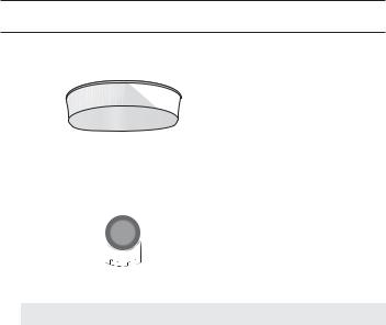
Installation base |
1 |
If installing it indoors or in a |
SNP-3302/3371 |
|
ceiling housing |
|||
|
|
|
|
10_ overview
Appearance |
Item Name |
Quantity |
Description |
Model Name |
|
Tapping Screw |
3 |
Used for installation on the wall |
|
|
or ceiling |
|
||
|
|
|
|
|
|
|
|
|
SNP-3302/3371 |
|
Template |
1 |
Product installation guide |
|
|
Hexagon screw |
3 |
Used for attaching the |
|
|
installation base to the camera |
|
||
|
|
|
|
|
|
|
|
Used for fixing the installation |
SNP- |
|
L Wrench |
1 |
base after attaching it to the |
|
|
3302H/3371H/3371TH |
|||
|
|
|
camera |
|
|
|
|
|
|
|
Installation base |
1 |
Bracket for mounting outdoors |
|
OVERVIEW ●
English _11
overview
AT A GLANCE (SNP-3302/3371)
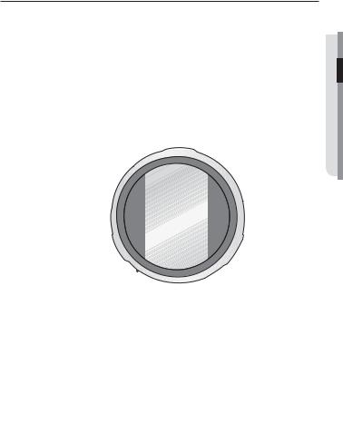
Appearance
c
b
|
Item |
Description |
Unlock button |
Used if installing the camera in the installation base. |
|
|
|
|
b Dome Cover |
Dome cover for the lens and unit protection. |
|
|
|
|
c Main unit |
Protect the internal PTZ mechanism from the direct sunlight. |
|
|
|
|
|
SD Memory Card |
Compartment for the SD memory card. |
Compartment |
||
Reset Button |
Pressing and holding this button for about 5 seconds will reset all camera |
|
settings to the factory default. |
||
|
After Service Port |
This is for the repair purpose only that is not available for the user. |
(A/S port) |
||
12_ overview

Bottom View of Installation
Base
|
|
Protocol |
2-1 2-2 |
2-3 2-4 |
||
|
|
STW |
OFF |
OFF |
OFF |
OFF |
|
|
Pelco-D |
OFF |
OFF |
OFF |
ON |
|
|
Pelco-P |
OFF |
OFF |
ON |
OFF |
|
|
SEC |
OFF |
OFF |
ON |
ON |
|
|
Panasonic |
OFF |
ON |
OFF |
OFF |
|
|
Vicon |
OFF |
ON |
OFF |
ON |
|
|
Honeywell |
OFF |
ON |
ON |
OFF |
|
|
AD |
OFF |
ON |
ON |
ON |
|
Baud |
2-5 2-6 |
Address Weight |
|||
|
2,400 |
ON |
ON |
1-1 |
1 |
|
|
4,800 |
ON |
OFF |
1-2 |
2 |
|
SW2 |
9,600 |
OFF |
OFF |
1-3 |
4 |
|
O |
ON |
ON |
1-8 |
128 |
||
|
19,200 |
OFF |
ON |
1-4 |
8 |
|
|
Termination |
2-10 2-11 |
1-5 |
16 |
||
|
1-6 |
32 |
||||
|
|
X |
OFF |
OFF |
1-7 |
64 |
|
|
ETC |
2-7 2-8 |
2-9 |
2-12 |
|
|
|
422 |
ON |
ON |
|
|
|
|
Response |
|
|
|
|
|
|
AUX1 |
|
|
|
|
|
|
AUX2 |
|
|
|
|
b |
|
SW1 |
|
|
|
|
|
|
|
|
|
|
|
Inner View of Installation Base
$POUSPMMFS |
39 |
(/%59%% % 59% |
|
39 |
|
|
59 |
|
|
59 |
|
|
(/% |
|
"VY |
$0. |
|
/ 0 |
" /0 |
"9*$0. *.07%$
7JEFP 0VU
|
1PXFS |
|
"$ _ 7 |
|
"6%*0@*/ "6%*0@065 |
"9*$0. *.07%$ |
"9*$0. *.07%$ |

 */ */ (/% */ */ (/% $ . / /$ $ . / /$
/$/ $0./$/ $0. (/% */ */ (/% */
*/
"MBSN
"MBSN 0/ "MBSN 0/
OVERVIEW ●
Item |
Description |
Communications |
Set the transfer rate and protocols. |
Setup Switch |
|
b ID Setup Switch |
Specify the camera ID. |
|
|
c Safety cable hook |
Cable hook that is designed for preventing an accidental fall of the product. |
|
|
Communications |
Used for RS-485 communications. |
and AUX Ports |
|
ConnectionsNetwork |
Network cable port. |
Audio Input Port |
Used to connect the audio input cable. |
|
|
English _13

overview
Item |
Description |
Audio Output Port |
Used to connect the audio output cable. |
|
|
Alarm I/O Port |
Used to connect the alarm I/O cable. |
|
|
Power Port |
Used to connect the power. |
|
|
Video Out Port |
Analog video output port. (for installation) |
14_ overview
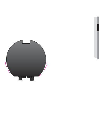
AT A GLANCE (SNP-3302H/3371H/3371TH)
Appearance
c
b
Item |
Description |
Main unit |
Protects the internal PTZ mechanism from the direct sunlight, rain or |
external impact. |
|
b Dome Cover |
Dome cover for the lens and unit protection. |
|
|
c Safety cable hook |
Cable hook that is designed for preventing an accidental fall of the product. |
|
|
OVERVIEW ●
English _15

overview
Bottom View of Installation
Base
Inner View of Installation Base
$POUSPMMFS |
39 |
(/%59%% % 59% |
39 |
||
|
59 |
|
|
59 |
|
|
(/% |
|
"VY |
$0. |
|
/ 0 |
" /0 |
"9*$0. *.07%$
7JEFP 0VU |
1PXFS "$ _ 7
|
"6%*0@*/ "6%*0@065 |
"9*$0. *.07%$ |
"9*$0. *.07%$ |

 */ */ (/% */ */ (/% $ . / /$ $ . / /$
/$/ $0./$/ $0. (/% */ */ (/% */
*/
"MBSN
"MBSN 0/ "MBSN 0/
|
b |
c |
|
|
|
|
|
Item |
|
Description |
|
Communications |
Set the transfer rate and protocols. |
|
|
Setup Switch |
|
||
b ID Setup Switch |
Specify the camera ID. |
|
|
Communications |
Used for RS-485 communications. |
|
|
c and AUX Ports |
|
||
Audio Input Port |
Used to connect the audio input cable. |
|
|
Audio Output Port |
Used to connect the audio output cable. |
|
|
ConnectionsNetwork |
|
Network cable port. |
|
Video Out Port |
Analog video output port. (for installation) |
|
|
Power Port |
|
Used to connect the power. |
|
Alarm I/O Port |
Used to connect the alarm I/O cable. |
|
|
16_ overview
installation & connection
Camera Wiring Interface Board
For the camera wiring, please refer to the picture below.
|
Power Supply |
|
AC24V 2.5A |
Video |
Power Input |
Output |
Ground |
|
ETHERNET
$POUSPMMFS |
39 |
(/%59%% % 59% |
39 |
||
|
59 |
|
|
59 |
|
|
(/% |
|
"VY |
$0. |
|
/ 0 |
" /0 |
"9*$0. *.07%$
7JEFP 0VU |
1PXFS "$ _ 7
|
"6%*0@*/ "6%*0@065 |
"9*$0. *.07%$ |
"9*$0. *.07%$ |
"MBSN 0/ "MBSN 0/

 */ */ (/% */ */ (/% $ . / /$ $ . / /$
/$/ $0./$/ $0. (/% */ */ (/% */
*/
"MBSN
Alarm
Alarm output
Alarm Input
Audio OUT
Audio IN
Communications and AUX
D+ D- TX+ TXGND COM N.O
CONNECTION & INSTALLATION ●
Refer to Control Signal |
AUX Output |
Connection Diagram |
|
English _17
installation & connection
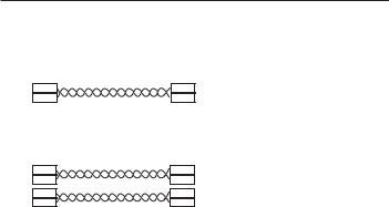
Control Signal Connection
• RS-485 Communications
Camera |
Controller |
D+
D-
TXD+
TXD-
• RS-422 Communications
Camera |
Controller |
D+
D-
TX+
TX-
TXD+
TXD-
RXD+
RXD-
JThe maximum power capacity of the alarm and AUX outputs is 30VDC/2A, 125VAC/0.5A, and 250VAC/0.25A.
When connecting alarm input and output cables, be sure to connect one cable to each terminal respectively.
To connect products over the camera’s capacity, please use an additional relay device.
Connecting the power connector and GND incorrectly to the NC/NO and COM ports can cause a short circuit which may lead to fire and damage the camera.
18_ installation & connection
DIP SWITCH SETTING (SNP-3302H/3371H/3371TH)
How to set up Protocols and ID DIP Switches
You can control various settings of the camera system using the Communication and ID DIP switches. Before installing the product, please set up the DIP switches according to the installation environment.
1.Set the switches according to your installation environment. For more detailed setup information, please refer to the chart on the next page.
2.The camera may malfunction if the switches are not fully turned On/Off; please double check the switches before finishing setup.
Communication Protocol
DIP Switch (SW2)
Camera ID DIP Switch (SW1)
CONNECTION & INSTALLATION ●
Communication Protocol DIP Switch Settings (SW2)
ON |
|
|
|
|
|
|
|
|
|
|
|
|
|
|
|
|
|
|
|
|
|
|
|
|
ON |
|
|
|
|
|
|
|
|
|
|
|
|
||||||||||||||
|
|
|
|
|
|
|
|
|
|
|
|
|
|
|
|
|
|
|
|
|
|
|
|
|
|
OFF
SW2
English _19

installation & connection
SW2 Pin No. |
Purpose |
1~4 |
Protocol Settings |
5~6 |
Baud Rate Settings |
7Transfer Method (RS-485/422) Settings
8Response Mode Settings
9RESERVED
10~11 Termination Settings
12RESERVED
•Protocol Settings
Select a communication protocol for the camera.
No. |
Protocol |
SW2-#1 |
SW2-#2 |
SW2-#3 |
SW2-#4 |
|||||||||||||
1 |
SAMSUNG-T |
OFF |
OFF |
OFF |
OFF |
|||||||||||||
2 |
PELCO-D |
OFF |
OFF |
OFF |
ON |
|||||||||||||
3 |
PELCO-P |
OFF |
OFF |
ON |
OFF |
|||||||||||||
4 |
SAMSUNG-E |
OFF |
OFF |
ON |
ON |
|
||||||||||||
5 |
Panasonic |
OFF |
ON |
OFF |
OFF |
|
||||||||||||
6 |
VICON |
OFF |
ON |
OFF |
ON |
|
||||||||||||
7 |
Honeywell |
OFF |
ON |
ON |
OFF |
|
||||||||||||
8 |
AD |
OFF |
ON |
ON |
ON |
|
||||||||||||
9 |
Reserved |
ON |
OFF |
OFF |
OFF |
|
||||||||||||
10 |
Reserved |
ON |
OFF |
OFF |
ON |
|
||||||||||||
11 |
Reserved |
ON |
OFF |
ON |
OFF |
|
||||||||||||
12 |
Reserved |
ON |
OFF |
ON |
ON |
|
||||||||||||
13 |
Reserved |
ON |
ON |
OFF |
OFF |
|
||||||||||||
14 |
Reserved |
ON |
ON |
OFF |
ON |
|
||||||||||||
15 |
Reserved |
ON |
ON |
ON |
OFF |
|
||||||||||||
16 |
Reserved |
ON |
ON |
ON |
ON |
|
||||||||||||
20_ installation & connection
• Baud Rate Settings |
|
|
|
|
Select the transfer speed of a selected communication protocol. |
|
|||
No. |
Baud Rate (BPS) |
SW2-#5 |
|
SW2-#6 |
1 |
2400 |
ON |
|
ON |
2 |
4800 |
ON |
|
OFF |
3 |
9600 |
OFF |
|
OFF |
4 |
19200 |
OFF |
|
ON |
• Communication Method Settings
Select a communication method for the camera.
|
Function |
ON |
OFF |
SW2-#7 |
Transfer Mode Switch |
RS-422(4Wire) |
RS-485(2Wire) |
• Communication Response Settings
Select a communication response method for the camera and controller: Response or No Response.
|
Function |
ON |
OFF |
SW2-#8 |
Response Mode Switch |
Response |
No Response |
• Termination Settings
To prevent the attenuation of communication signals between the camera and controller, the items at the end of line must be set up with the termination settings.
Camera Input Position |
SW2-#10 |
SW2-#11 |
Termination of Longest Path |
ON |
ON |
On the Path |
OFF |
OFF |
MThe default value is shaded in each setting table.
To use a third party controller with this product, please contact our After-Sales Service or Technology Department.
CONNECTION & INSTALLATION ●
English _21

installation & connection
Camera ID DIP Switch Settings (SW1)
To set up camera IDs, refer to the “Camera ID Chart” next.
|
|
|
|
|
|
|
|
|
|
|
|
|
|
|
|
ON |
|
|
|
|
|
|
|
|
|
|
|
|
|
|
|
|
|
|
ON |
|
|
|
|
|
|
|
|
|
|
|
|
|
|
|
|
|
|
|
|
|
|
|
|
|
|
|
|
|
|
|
|
|
|
|
|
|
|
||||
|
|
|
|
|
|
|
|
|
|
|
|
|
|
|
|
|
|
|
|
|
|
|
|
|
|
|
|
|
|
|
|
|
|
|
|
OFF |
|
|
|
|
|
|
|
|
|
|
|
|
|
|
|
|
|
|
|
|
|
|
|
|
|
|
|
|
|
|
|
|
|
|
|
|
|
|
|
|
|
|
|
|
|
|
|
|
|
|
|
|
|
|
|
|
|
|
|
|
|
|
|
|
|
|
|
|
|
|
|
|
|
|
|
|
|
|
||
|
|
|
|
• Camera ID Chart |
|
|
|
|
SW1 |
|
|
|
|
|
|
|
|
|
|
|||||||||||||||||||
|
|
|
|
|
|
|
|
|
|
|
|
|
|
|
|
|
|
|
|
|
|
|
||||||||||||||||
|
|
|
|
|
|
|
|
|
|
|
|
|
ID |
SW1-#1 |
|
SW1-#2 |
|
SW1-#3 |
|
SW1-#4 |
|
SW1-#5 |
|
SW1-#6 |
SW1-#7 |
SW1-#8 |
||||||||||||
|
1 |
ON/OFF |
|
OFF |
|
OFF |
|
OFF |
|
OFF |
|
|
OFF |
OFF |
OFF |
|||||||||||||||||||||||
|
2 |
OFF |
|
ON |
|
OFF |
|
OFF |
|
OFF |
|
|
OFF |
OFF |
OFF |
|||||||||||||||||||||||
|
3 |
ON |
|
ON |
|
OFF |
|
OFF |
|
OFF |
|
|
OFF |
OFF |
OFF |
|||||||||||||||||||||||
|
4 |
OFF |
|
OFF |
|
ON |
|
OFF |
|
OFF |
|
|
OFF |
OFF |
OFF |
|||||||||||||||||||||||
|
5 |
ON |
|
OFF |
|
ON |
|
OFF |
|
OFF |
|
|
OFF |
OFF |
OFF |
|||||||||||||||||||||||
|
6 |
OFF |
|
ON |
|
ON |
|
OFF |
|
OFF |
|
|
OFF |
OFF |
OFF |
|||||||||||||||||||||||
|
7 |
ON |
|
ON |
|
ON |
|
OFF |
|
OFF |
|
|
OFF |
OFF |
OFF |
|||||||||||||||||||||||
|
8 |
OFF |
|
OFF |
|
OFF |
|
|
ON |
|
OFF |
|
|
OFF |
OFF |
OFF |
||||||||||||||||||||||
|
9 |
ON |
|
OFF |
|
OFF |
|
|
ON |
|
OFF |
|
|
OFF |
OFF |
OFF |
||||||||||||||||||||||
|
10 |
OFF |
|
ON |
|
OFF |
|
|
ON |
|
OFF |
|
|
OFF |
OFF |
OFF |
||||||||||||||||||||||
|
11 |
ON |
|
ON |
|
OFF |
|
|
ON |
|
OFF |
|
|
OFF |
OFF |
OFF |
||||||||||||||||||||||
|
12 |
OFF |
|
OFF |
|
ON |
|
|
ON |
|
OFF |
|
|
OFF |
OFF |
OFF |
||||||||||||||||||||||
|
13 |
ON |
|
OFF |
|
ON |
|
|
ON |
|
OFF |
|
|
OFF |
OFF |
OFF |
||||||||||||||||||||||
14 |
OFF |
|
ON |
|
ON |
|
|
ON |
|
OFF |
|
|
OFF |
OFF |
OFF |
|||||||||||||||||||||||
|
15 |
ON |
|
ON |
|
ON |
|
|
ON |
|
OFF |
|
|
OFF |
OFF |
OFF |
||||||||||||||||||||||
|
16 |
OFF |
|
OFF |
|
OFF |
|
OFF |
|
|
ON |
|
|
OFF |
OFF |
OFF |
||||||||||||||||||||||
|
17 |
ON |
|
OFF |
|
OFF |
|
OFF |
|
|
ON |
|
|
OFF |
OFF |
OFF |
||||||||||||||||||||||
|
18 |
OFF |
|
ON |
|
OFF |
|
OFF |
|
|
ON |
|
|
OFF |
OFF |
OFF |
||||||||||||||||||||||
|
19 |
ON |
|
ON |
|
OFF |
|
OFF |
|
|
ON |
|
|
OFF |
OFF |
OFF |
||||||||||||||||||||||
|
20 |
OFF |
|
OFF |
|
ON |
|
OFF |
|
|
ON |
|
|
OFF |
OFF |
OFF |
||||||||||||||||||||||
|
21 |
ON |
|
OFF |
|
ON |
|
OFF |
|
|
ON |
|
|
OFF |
OFF |
OFF |
||||||||||||||||||||||
|
22 |
OFF |
|
ON |
|
ON |
|
OFF |
|
|
ON |
|
|
OFF |
OFF |
OFF |
||||||||||||||||||||||
|
23 |
ON |
|
ON |
|
ON |
|
OFF |
|
|
ON |
|
|
OFF |
OFF |
OFF |
||||||||||||||||||||||
|
24 |
OFF |
|
OFF |
|
OFF |
|
|
ON |
|
|
ON |
|
|
OFF |
OFF |
OFF |
|||||||||||||||||||||
|
25 |
ON |
|
OFF |
|
OFF |
|
|
ON |
|
|
ON |
|
|
OFF |
OFF |
OFF |
|||||||||||||||||||||
|
26 |
OFF |
|
ON |
|
OFF |
|
|
ON |
|
|
ON |
|
|
OFF |
OFF |
OFF |
|||||||||||||||||||||
27 |
ON |
|
ON |
|
OFF |
|
|
ON |
|
|
ON |
|
|
OFF |
OFF |
OFF |
||||||||||||||||||||||
|
|
28 |
OFF |
|
OFF |
|
ON |
|
|
ON |
|
|
ON |
|
|
OFF |
OFF |
OFF |
||||||||||||||||||||
22_ installation & connection

|
|
|
|
|
|
|
|
|
|
|
|
ID |
SW1-#1 |
SW1-#2 |
SW1-#3 |
SW1-#4 |
SW1-#5 |
SW1-#6 |
SW1-#7 |
SW1-#8 |
|
29 |
ON |
OFF |
ON |
ON |
ON |
OFF |
OFF |
OFF |
|||||||||||||
|
30 |
OFF |
ON |
ON |
ON |
ON |
OFF |
OFF |
OFF |
||||||||||||
|
31 |
ON |
ON |
ON |
ON |
ON |
OFF |
OFF |
OFF |
||||||||||||
|
32 |
OFF |
OFF |
OFF |
OFF |
OFF |
ON |
OFF |
OFF |
||||||||||||
|
33 |
ON |
OFF |
OFF |
OFF |
OFF |
ON |
OFF |
OFF |
||||||||||||
|
34 |
OFF |
ON |
OFF |
OFF |
OFF |
ON |
OFF |
OFF |
||||||||||||
|
35 |
ON |
ON |
OFF |
OFF |
OFF |
ON |
OFF |
OFF |
||||||||||||
|
36 |
OFF |
OFF |
ON |
OFF |
OFF |
ON |
OFF |
OFF |
||||||||||||
|
37 |
ON |
OFF |
ON |
OFF |
OFF |
ON |
OFF |
OFF |
||||||||||||
|
38 |
OFF |
ON |
ON |
OFF |
OFF |
ON |
OFF |
OFF |
||||||||||||
|
39 |
ON |
ON |
ON |
OFF |
OFF |
ON |
OFF |
OFF |
||||||||||||
|
40 |
OFF |
OFF |
OFF |
ON |
OFF |
ON |
OFF |
OFF |
||||||||||||
|
41 |
ON |
OFF |
OFF |
ON |
OFF |
ON |
OFF |
OFF |
|
|||||||||||
42 |
OFF |
ON |
OFF |
ON |
OFF |
ON |
OFF |
OFF |
|||||||||||||
43 |
ON |
ON |
OFF |
ON |
OFF |
ON |
OFF |
OFF |
|||||||||||||
|
44 |
OFF |
OFF |
ON |
ON |
OFF |
ON |
OFF |
OFF |
||||||||||||
|
45 |
ON |
OFF |
ON |
ON |
OFF |
ON |
OFF |
OFF |
||||||||||||
|
46 |
OFF |
ON |
ON |
ON |
OFF |
ON |
OFF |
OFF |
||||||||||||
|
47 |
ON |
ON |
ON |
ON |
OFF |
ON |
OFF |
OFF |
||||||||||||
|
48 |
OFF |
OFF |
OFF |
OFF |
ON |
ON |
OFF |
OFF |
||||||||||||
|
49 |
ON |
OFF |
OFF |
OFF |
ON |
ON |
OFF |
OFF |
||||||||||||
|
50 |
OFF |
ON |
OFF |
OFF |
ON |
ON |
OFF |
OFF |
||||||||||||
|
51 |
ON |
ON |
OFF |
OFF |
ON |
ON |
OFF |
OFF |
||||||||||||
|
52 |
OFF |
OFF |
ON |
OFF |
ON |
ON |
OFF |
OFF |
||||||||||||
|
53 |
ON |
OFF |
ON |
OFF |
ON |
ON |
OFF |
OFF |
||||||||||||
|
54 |
OFF |
ON |
ON |
OFF |
ON |
ON |
OFF |
OFF |
|
|||||||||||
55 |
ON |
ON |
ON |
OFF |
ON |
ON |
OFF |
OFF |
|||||||||||||
56 |
OFF |
OFF |
OFF |
ON |
ON |
ON |
OFF |
OFF |
|||||||||||||
|
57 |
ON |
OFF |
OFF |
ON |
ON |
ON |
OFF |
OFF |
||||||||||||
|
58 |
OFF |
ON |
OFF |
ON |
ON |
ON |
OFF |
OFF |
||||||||||||
|
59 |
ON |
ON |
OFF |
ON |
ON |
ON |
OFF |
OFF |
||||||||||||
|
60 |
OFF |
OFF |
ON |
ON |
ON |
ON |
OFF |
OFF |
||||||||||||
|
61 |
ON |
OFF |
ON |
ON |
ON |
ON |
OFF |
OFF |
||||||||||||
|
62 |
OFF |
ON |
ON |
ON |
ON |
ON |
OFF |
OFF |
||||||||||||
|
63 |
ON |
ON |
ON |
ON |
ON |
ON |
OFF |
OFF |
||||||||||||
|
64 |
OFF |
OFF |
OFF |
OFF |
OFF |
OFF |
ON |
OFF |
||||||||||||
|
65 |
ON |
OFF |
OFF |
OFF |
OFF |
OFF |
ON |
OFF |
||||||||||||
|
66 |
OFF |
ON |
OFF |
OFF |
OFF |
OFF |
ON |
OFF |
||||||||||||
|
67 |
ON |
ON |
OFF |
OFF |
OFF |
OFF |
ON |
OFF |
|
|||||||||||
CONNECTION & INSTALLATION ●
English _23

installation & connection
|
|
|
|
|
|
|
|
|
|
|
|
ID |
SW1-#1 |
SW1-#2 |
SW1-#3 |
SW1-#4 |
SW1-#5 |
SW1-#6 |
SW1-#7 |
SW1-#8 |
|
68 |
OFF |
OFF |
ON |
OFF |
OFF |
OFF |
ON |
OFF |
|||||||||||||
|
69 |
ON |
OFF |
ON |
OFF |
OFF |
OFF |
ON |
OFF |
||||||||||||
|
70 |
OFF |
ON |
ON |
OFF |
OFF |
OFF |
ON |
OFF |
||||||||||||
|
71 |
ON |
ON |
ON |
OFF |
OFF |
OFF |
ON |
OFF |
||||||||||||
|
72 |
OFF |
OFF |
OFF |
ON |
OFF |
OFF |
ON |
OFF |
||||||||||||
|
73 |
ON |
OFF |
OFF |
ON |
OFF |
OFF |
ON |
OFF |
||||||||||||
|
74 |
OFF |
ON |
OFF |
ON |
OFF |
OFF |
ON |
OFF |
||||||||||||
|
75 |
ON |
ON |
OFF |
ON |
OFF |
OFF |
ON |
OFF |
||||||||||||
|
76 |
OFF |
OFF |
ON |
ON |
OFF |
OFF |
ON |
OFF |
||||||||||||
|
77 |
ON |
OFF |
ON |
ON |
OFF |
OFF |
ON |
OFF |
||||||||||||
|
78 |
OFF |
ON |
ON |
ON |
OFF |
OFF |
ON |
OFF |
||||||||||||
|
79 |
ON |
ON |
ON |
ON |
OFF |
OFF |
ON |
OFF |
||||||||||||
|
80 |
OFF |
OFF |
OFF |
OFF |
ON |
OFF |
ON |
OFF |
|
|||||||||||
81 |
ON |
OFF |
OFF |
OFF |
ON |
OFF |
ON |
OFF |
|||||||||||||
82 |
OFF |
ON |
OFF |
OFF |
ON |
OFF |
ON |
OFF |
|||||||||||||
|
83 |
ON |
ON |
OFF |
OFF |
ON |
OFF |
ON |
OFF |
||||||||||||
|
84 |
OFF |
OFF |
ON |
OFF |
ON |
OFF |
ON |
OFF |
||||||||||||
|
85 |
ON |
OFF |
ON |
OFF |
ON |
OFF |
ON |
OFF |
||||||||||||
|
86 |
OFF |
ON |
ON |
OFF |
ON |
OFF |
ON |
OFF |
||||||||||||
|
87 |
ON |
ON |
ON |
OFF |
ON |
OFF |
ON |
OFF |
||||||||||||
|
88 |
OFF |
OFF |
OFF |
ON |
ON |
OFF |
ON |
OFF |
||||||||||||
|
89 |
ON |
OFF |
OFF |
ON |
ON |
OFF |
ON |
OFF |
||||||||||||
|
90 |
OFF |
ON |
OFF |
ON |
ON |
OFF |
ON |
OFF |
||||||||||||
|
91 |
ON |
ON |
OFF |
ON |
ON |
OFF |
ON |
OFF |
||||||||||||
|
92 |
OFF |
OFF |
ON |
ON |
ON |
OFF |
ON |
OFF |
||||||||||||
|
93 |
ON |
OFF |
ON |
ON |
ON |
OFF |
ON |
OFF |
|
|||||||||||
94 |
OFF |
ON |
ON |
ON |
ON |
OFF |
ON |
OFF |
|||||||||||||
95 |
ON |
ON |
ON |
ON |
ON |
OFF |
ON |
OFF |
|||||||||||||
|
96 |
OFF |
OFF |
OFF |
OFF |
OFF |
ON |
ON |
OFF |
||||||||||||
|
97 |
ON |
OFF |
OFF |
OFF |
OFF |
ON |
ON |
OFF |
||||||||||||
|
98 |
OFF |
ON |
OFF |
OFF |
OFF |
ON |
ON |
OFF |
||||||||||||
|
99 |
ON |
ON |
OFF |
OFF |
OFF |
ON |
ON |
OFF |
||||||||||||
|
100 |
OFF |
OFF |
ON |
OFF |
OFF |
ON |
ON |
OFF |
||||||||||||
|
101 |
ON |
OFF |
ON |
OFF |
OFF |
ON |
ON |
OFF |
||||||||||||
|
102 |
OFF |
ON |
ON |
OFF |
OFF |
ON |
ON |
OFF |
||||||||||||
|
103 |
ON |
ON |
ON |
OFF |
OFF |
ON |
ON |
OFF |
||||||||||||
|
104 |
OFF |
OFF |
OFF |
ON |
OFF |
ON |
ON |
OFF |
||||||||||||
|
105 |
ON |
OFF |
OFF |
ON |
OFF |
ON |
ON |
OFF |
||||||||||||
|
106 |
OFF |
ON |
OFF |
ON |
OFF |
ON |
ON |
OFF |
|
|||||||||||
24_ installation & connection

|
|
|
|
|
|
|
|
|
|
|
|
ID |
SW1-#1 |
SW1-#2 |
SW1-#3 |
SW1-#4 |
SW1-#5 |
SW1-#6 |
SW1-#7 |
SW1-#8 |
|
107 |
ON |
ON |
OFF |
ON |
OFF |
ON |
ON |
OFF |
|||||||||||||
|
108 |
OFF |
OFF |
ON |
ON |
OFF |
ON |
ON |
OFF |
||||||||||||
|
109 |
ON |
OFF |
ON |
ON |
OFF |
ON |
ON |
OFF |
||||||||||||
|
110 |
OFF |
ON |
ON |
ON |
OFF |
ON |
ON |
OFF |
||||||||||||
|
111 |
ON |
ON |
ON |
ON |
OFF |
ON |
ON |
OFF |
||||||||||||
|
112 |
OFF |
OFF |
OFF |
OFF |
ON |
ON |
ON |
OFF |
||||||||||||
|
113 |
ON |
OFF |
OFF |
OFF |
ON |
ON |
ON |
OFF |
||||||||||||
|
114 |
OFF |
ON |
OFF |
OFF |
ON |
ON |
ON |
OFF |
||||||||||||
|
115 |
ON |
ON |
OFF |
OFF |
ON |
ON |
ON |
OFF |
||||||||||||
|
116 |
OFF |
OFF |
ON |
OFF |
ON |
ON |
ON |
OFF |
||||||||||||
|
117 |
ON |
OFF |
ON |
OFF |
ON |
ON |
ON |
OFF |
||||||||||||
|
118 |
OFF |
ON |
ON |
OFF |
ON |
ON |
ON |
OFF |
||||||||||||
|
119 |
ON |
ON |
ON |
OFF |
ON |
ON |
ON |
OFF |
|
|||||||||||
120 |
OFF |
OFF |
OFF |
ON |
ON |
ON |
ON |
OFF |
|||||||||||||
121 |
ON |
OFF |
OFF |
ON |
ON |
ON |
ON |
OFF |
|||||||||||||
|
122 |
OFF |
ON |
OFF |
ON |
ON |
ON |
ON |
OFF |
||||||||||||
|
123 |
ON |
ON |
OFF |
ON |
ON |
ON |
ON |
OFF |
||||||||||||
|
124 |
OFF |
OFF |
ON |
ON |
ON |
ON |
ON |
OFF |
||||||||||||
|
125 |
ON |
OFF |
ON |
ON |
ON |
ON |
ON |
OFF |
||||||||||||
|
126 |
OFF |
ON |
ON |
ON |
ON |
ON |
ON |
OFF |
||||||||||||
|
127 |
ON |
ON |
ON |
ON |
ON |
ON |
ON |
OFF |
||||||||||||
|
128 |
OFF |
OFF |
OFF |
OFF |
OFF |
OFF |
OFF |
ON |
||||||||||||
|
129 |
ON |
OFF |
OFF |
OFF |
OFF |
OFF |
OFF |
ON |
||||||||||||
|
130 |
OFF |
ON |
OFF |
OFF |
OFF |
OFF |
OFF |
ON |
||||||||||||
|
131 |
ON |
ON |
OFF |
OFF |
OFF |
OFF |
OFF |
ON |
||||||||||||
|
132 |
OFF |
OFF |
ON |
OFF |
OFF |
OFF |
OFF |
ON |
|
|||||||||||
133 |
ON |
OFF |
ON |
OFF |
OFF |
OFF |
OFF |
ON |
|||||||||||||
134 |
OFF |
ON |
ON |
OFF |
OFF |
OFF |
OFF |
ON |
|||||||||||||
|
135 |
ON |
ON |
ON |
OFF |
OFF |
OFF |
OFF |
ON |
||||||||||||
|
136 |
OFF |
OFF |
OFF |
ON |
OFF |
OFF |
OFF |
ON |
||||||||||||
|
137 |
ON |
OFF |
OFF |
ON |
OFF |
OFF |
OFF |
ON |
||||||||||||
|
138 |
OFF |
ON |
OFF |
ON |
OFF |
OFF |
OFF |
ON |
||||||||||||
|
139 |
ON |
ON |
OFF |
ON |
OFF |
OFF |
OFF |
ON |
||||||||||||
|
140 |
OFF |
OFF |
ON |
ON |
OFF |
OFF |
OFF |
ON |
||||||||||||
|
141 |
ON |
OFF |
ON |
ON |
OFF |
OFF |
OFF |
ON |
||||||||||||
|
142 |
OFF |
ON |
ON |
ON |
OFF |
OFF |
OFF |
ON |
||||||||||||
|
143 |
ON |
ON |
ON |
ON |
OFF |
OFF |
OFF |
ON |
||||||||||||
|
144 |
OFF |
OFF |
OFF |
OFF |
ON |
OFF |
OFF |
ON |
||||||||||||
|
145 |
ON |
OFF |
OFF |
OFF |
ON |
OFF |
OFF |
ON |
|
|||||||||||
CONNECTION & INSTALLATION ●
English _25

installation & connection
|
|
|
|
|
|
|
|
|
|
|
|
ID |
SW1-#1 |
SW1-#2 |
SW1-#3 |
SW1-#4 |
SW1-#5 |
SW1-#6 |
SW1-#7 |
SW1-#8 |
|
146 |
OFF |
ON |
OFF |
OFF |
ON |
OFF |
OFF |
ON |
|||||||||||||
|
147 |
ON |
ON |
OFF |
OFF |
ON |
OFF |
OFF |
ON |
||||||||||||
|
148 |
OFF |
OFF |
ON |
OFF |
ON |
OFF |
OFF |
ON |
||||||||||||
|
149 |
ON |
OFF |
ON |
OFF |
ON |
OFF |
OFF |
ON |
||||||||||||
|
150 |
OFF |
ON |
ON |
OFF |
ON |
OFF |
OFF |
ON |
||||||||||||
|
151 |
ON |
ON |
ON |
OFF |
ON |
OFF |
OFF |
ON |
||||||||||||
|
152 |
OFF |
OFF |
OFF |
ON |
ON |
OFF |
OFF |
ON |
||||||||||||
|
153 |
ON |
OFF |
OFF |
ON |
ON |
OFF |
OFF |
ON |
||||||||||||
|
154 |
OFF |
ON |
OFF |
ON |
ON |
OFF |
OFF |
ON |
||||||||||||
|
155 |
ON |
ON |
OFF |
ON |
ON |
OFF |
OFF |
ON |
||||||||||||
|
156 |
OFF |
OFF |
ON |
ON |
ON |
OFF |
OFF |
ON |
||||||||||||
|
157 |
ON |
OFF |
ON |
ON |
ON |
OFF |
OFF |
ON |
||||||||||||
|
158 |
OFF |
ON |
ON |
ON |
ON |
OFF |
OFF |
ON |
|
|||||||||||
159 |
ON |
ON |
ON |
ON |
ON |
OFF |
OFF |
ON |
|||||||||||||
160 |
OFF |
OFF |
OFF |
OFF |
OFF |
ON |
OFF |
ON |
|||||||||||||
|
161 |
ON |
OFF |
OFF |
OFF |
OFF |
ON |
OFF |
ON |
||||||||||||
|
162 |
OFF |
ON |
OFF |
OFF |
OFF |
ON |
OFF |
ON |
||||||||||||
|
163 |
ON |
ON |
OFF |
OFF |
OFF |
ON |
OFF |
ON |
||||||||||||
|
164 |
OFF |
OFF |
ON |
OFF |
OFF |
ON |
OFF |
ON |
||||||||||||
|
165 |
ON |
OFF |
ON |
OFF |
OFF |
ON |
OFF |
ON |
||||||||||||
|
166 |
OFF |
ON |
ON |
OFF |
OFF |
ON |
OFF |
ON |
||||||||||||
|
167 |
ON |
ON |
ON |
OFF |
OFF |
ON |
OFF |
ON |
||||||||||||
|
168 |
OFF |
OFF |
OFF |
ON |
OFF |
ON |
OFF |
ON |
||||||||||||
|
169 |
ON |
OFF |
OFF |
ON |
OFF |
ON |
OFF |
ON |
||||||||||||
|
170 |
OFF |
ON |
OFF |
ON |
OFF |
ON |
OFF |
ON |
||||||||||||
|
171 |
ON |
ON |
OFF |
ON |
OFF |
ON |
OFF |
ON |
|
|||||||||||
172 |
OFF |
OFF |
ON |
ON |
OFF |
ON |
OFF |
ON |
|||||||||||||
173 |
ON |
OFF |
ON |
ON |
OFF |
ON |
OFF |
ON |
|||||||||||||
|
174 |
OFF |
ON |
ON |
ON |
OFF |
ON |
OFF |
ON |
||||||||||||
|
175 |
ON |
ON |
ON |
ON |
OFF |
ON |
OFF |
ON |
||||||||||||
|
176 |
OFF |
OFF |
OFF |
OFF |
ON |
ON |
OFF |
ON |
||||||||||||
|
177 |
ON |
OFF |
OFF |
OFF |
ON |
ON |
OFF |
ON |
||||||||||||
|
178 |
OFF |
ON |
OFF |
OFF |
ON |
ON |
OFF |
ON |
||||||||||||
|
179 |
ON |
ON |
OFF |
OFF |
ON |
ON |
OFF |
ON |
||||||||||||
|
180 |
OFF |
OFF |
ON |
OFF |
ON |
ON |
OFF |
ON |
||||||||||||
|
181 |
ON |
OFF |
ON |
OFF |
ON |
ON |
OFF |
ON |
||||||||||||
|
182 |
OFF |
ON |
ON |
OFF |
ON |
ON |
OFF |
ON |
||||||||||||
|
183 |
ON |
ON |
ON |
OFF |
ON |
ON |
OFF |
ON |
||||||||||||
|
184 |
OFF |
OFF |
OFF |
ON |
ON |
ON |
OFF |
ON |
|
|||||||||||
26_ installation & connection

|
|
|
|
|
|
|
|
|
|
ID |
SW1-#1 |
SW1-#2 |
SW1-#3 |
SW1-#4 |
SW1-#5 |
SW1-#6 |
SW1-#7 |
SW1-#8 |
|
|
|
|
185 |
ON |
OFF |
OFF |
ON |
ON |
ON |
OFF |
ON |
|
|
|
|
||||||||||
|
186 |
OFF |
ON |
OFF |
ON |
ON |
ON |
OFF |
ON |
|
|
|
|
|||||||||
|
187 |
ON |
ON |
OFF |
ON |
ON |
ON |
OFF |
ON |
|
|
|
|
|||||||||
|
|
|
|
188 |
OFF |
OFF |
ON |
ON |
ON |
ON |
OFF |
ON |
|
|
● |
|
||||||
|
189 |
ON |
OFF |
ON |
ON |
ON |
ON |
OFF |
ON |
|
|
INSTALLATION |
|
|||||||||
193 |
ON |
OFF |
OFF |
OFF |
OFF |
OFF |
ON |
ON |
|
|
|
|||||||||||
190 |
OFF |
ON |
ON |
ON |
ON |
ON |
OFF |
ON |
|
|
|
|
||||||||||
|
191 |
ON |
ON |
ON |
ON |
ON |
ON |
OFF |
ON |
|
|
|
|
|||||||||
|
192 |
OFF |
OFF |
OFF |
OFF |
OFF |
OFF |
ON |
ON |
& |
|
|||||||||||
|
|
|
|
|
|
|
|
|
|
|
|
|
|
|
|
|
|
|
|
|||
194 |
OFF |
ON |
OFF |
OFF |
OFF |
OFF |
ON |
ON |
|
|||||||||||||
|
|
CONNECTION |
|
|||||||||||||||||||
|
|
|
|
|
|
|
|
|
|
|
|
|
||||||||||
198 |
OFF |
ON |
ON |
OFF |
OFF |
OFF |
ON |
ON |
|
|
||||||||||||
195 |
ON |
ON |
OFF |
OFF |
OFF |
OFF |
ON |
ON |
|
|
|
|
||||||||||
|
196 |
OFF |
OFF |
ON |
OFF |
OFF |
OFF |
ON |
ON |
|
|
|
|
|||||||||
197 |
ON |
OFF |
ON |
OFF |
OFF |
OFF |
ON |
ON |
|
|
|
|
||||||||||
|
|
|
|
|
|
|
|
|
|
|
|
|
|
|
||||||||
199 |
ON |
ON |
ON |
OFF |
OFF |
OFF |
ON |
ON |
|
|
|
|
||||||||||
|
200 |
OFF |
OFF |
OFF |
ON |
OFF |
OFF |
ON |
ON |
|
|
|
|
|||||||||
|
|
|
|
|
|
|||||||||||||||||
|
201 |
ON |
OFF |
OFF |
ON |
OFF |
OFF |
ON |
ON |
|
|
|
|
|||||||||
|
202 |
OFF |
ON |
OFF |
ON |
OFF |
OFF |
ON |
ON |
|
|
|
|
|||||||||
|
203 |
ON |
ON |
OFF |
ON |
OFF |
OFF |
ON |
ON |
|
|
|
|
|||||||||
|
204 |
OFF |
OFF |
ON |
ON |
OFF |
OFF |
ON |
ON |
|
|
|
|
|||||||||
|
205 |
ON |
OFF |
ON |
ON |
OFF |
OFF |
ON |
ON |
|
|
|
|
|||||||||
|
206 |
OFF |
ON |
ON |
ON |
OFF |
OFF |
ON |
ON |
|
|
|
|
|||||||||
|
207 |
ON |
ON |
ON |
ON |
OFF |
OFF |
ON |
ON |
|
|
|
|
|||||||||
|
208 |
OFF |
OFF |
OFF |
OFF |
ON |
OFF |
ON |
ON |
|
|
|
|
|||||||||
|
209 |
ON |
OFF |
OFF |
OFF |
ON |
OFF |
ON |
ON |
|
|
|
|
|||||||||
|
210 |
OFF |
ON |
OFF |
OFF |
ON |
OFF |
ON |
ON |
|
|
|
|
|||||||||
211 |
ON |
ON |
OFF |
OFF |
ON |
OFF |
ON |
ON |
|
|
|
|
||||||||||
212 |
OFF |
OFF |
ON |
OFF |
ON |
OFF |
ON |
ON |
|
|
|
|
||||||||||
|
213 |
ON |
OFF |
ON |
OFF |
ON |
OFF |
ON |
ON |
|
|
|
|
|||||||||
|
214 |
OFF |
ON |
ON |
OFF |
ON |
OFF |
ON |
ON |
|
|
|
|
|||||||||
|
215 |
ON |
ON |
ON |
OFF |
ON |
OFF |
ON |
ON |
|
|
|
|
|||||||||
|
216 |
OFF |
OFF |
OFF |
ON |
ON |
OFF |
ON |
ON |
|
|
|
|
|||||||||
|
217 |
ON |
OFF |
OFF |
ON |
ON |
OFF |
ON |
ON |
|
|
|
|
|||||||||
|
218 |
OFF |
ON |
OFF |
ON |
ON |
OFF |
ON |
ON |
|
|
|
|
|||||||||
|
219 |
ON |
ON |
OFF |
ON |
ON |
OFF |
ON |
ON |
|
|
|
|
|||||||||
|
220 |
OFF |
OFF |
ON |
ON |
ON |
OFF |
ON |
ON |
|
|
|
|
|||||||||
|
221 |
ON |
OFF |
ON |
ON |
ON |
OFF |
ON |
ON |
|
|
|
|
|||||||||
|
222 |
OFF |
ON |
ON |
ON |
ON |
OFF |
ON |
ON |
|
|
|
|
|||||||||
English _27

installation & connection
|
|
|
|
|
|
ID |
SW1-#1 |
SW1-#2 |
SW1-#3 |
SW1-#4 |
SW1-#5 |
SW1-#6 |
SW1-#7 |
SW1-#8 |
|
223 |
ON |
ON |
ON |
ON |
ON |
OFF |
ON |
ON |
|||||||
|
224 |
OFF |
OFF |
OFF |
OFF |
OFF |
ON |
ON |
ON |
||||||
|
225 |
ON |
OFF |
OFF |
OFF |
OFF |
ON |
ON |
ON |
||||||
|
226 |
OFF |
ON |
OFF |
OFF |
OFF |
ON |
ON |
ON |
||||||
|
227 |
ON |
ON |
OFF |
OFF |
OFF |
ON |
ON |
ON |
||||||
|
228 |
OFF |
OFF |
ON |
OFF |
OFF |
ON |
ON |
ON |
||||||
|
229 |
ON |
OFF |
ON |
OFF |
OFF |
ON |
ON |
ON |
||||||
|
230 |
OFF |
ON |
ON |
OFF |
OFF |
ON |
ON |
ON |
||||||
|
231 |
ON |
ON |
ON |
OFF |
OFF |
ON |
ON |
ON |
||||||
|
232 |
OFF |
OFF |
OFF |
ON |
OFF |
ON |
ON |
ON |
||||||
|
233 |
ON |
OFF |
OFF |
ON |
OFF |
ON |
ON |
ON |
||||||
|
234 |
OFF |
ON |
OFF |
ON |
OFF |
ON |
ON |
ON |
||||||
|
235 |
ON |
ON |
OFF |
ON |
OFF |
ON |
ON |
ON |
|
|||||
236 |
OFF |
OFF |
ON |
ON |
OFF |
ON |
ON |
ON |
|||||||
237 |
ON |
OFF |
ON |
ON |
OFF |
ON |
ON |
ON |
|||||||
|
238 |
OFF |
ON |
ON |
ON |
OFF |
ON |
ON |
ON |
||||||
|
239 |
ON |
ON |
ON |
ON |
OFF |
ON |
ON |
ON |
||||||
|
240 |
OFF |
OFF |
OFF |
OFF |
ON |
ON |
ON |
ON |
||||||
|
241 |
ON |
OFF |
OFF |
OFF |
ON |
ON |
ON |
ON |
||||||
|
242 |
OFF |
ON |
OFF |
OFF |
ON |
ON |
ON |
ON |
||||||
|
243 |
ON |
ON |
OFF |
OFF |
ON |
ON |
ON |
ON |
||||||
|
244 |
OFF |
OFF |
ON |
OFF |
ON |
ON |
ON |
ON |
||||||
|
245 |
ON |
OFF |
ON |
OFF |
ON |
ON |
ON |
ON |
||||||
|
246 |
OFF |
ON |
ON |
OFF |
ON |
ON |
ON |
ON |
||||||
|
247 |
ON |
ON |
ON |
OFF |
ON |
ON |
ON |
ON |
||||||
|
248 |
OFF |
OFF |
OFF |
ON |
ON |
ON |
ON |
ON |
|
|||||
249 |
ON |
OFF |
OFF |
ON |
ON |
ON |
ON |
ON |
|||||||
250 |
OFF |
ON |
OFF |
ON |
ON |
ON |
ON |
ON |
|||||||
|
251 |
ON |
ON |
OFF |
ON |
ON |
ON |
ON |
ON |
||||||
|
252 |
OFF |
OFF |
ON |
ON |
ON |
ON |
ON |
ON |
||||||
|
253 |
ON |
OFF |
ON |
ON |
ON |
ON |
ON |
ON |
||||||
|
254 |
OFF |
ON |
ON |
ON |
ON |
ON |
ON |
ON |
||||||
|
255 |
ON |
ON |
ON |
ON |
ON |
ON |
ON |
ON |
||||||
|
|
|
|
|
|
|
|
|
|
|
|
|
|
|
|
28_ installation & connection
INSTALLATION
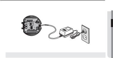
Preparing Adapter and Cable
Plug the power adapter into a power outlet.
% % 59% 59% (/%. " $0" /0
 0VU7JEFP
*/ */ (/% */ */ (/%$. / /$ $. / /$
Check out the rated voltage and current before making connections.
Rated Power |
Allowable Input Voltage |
Current Consumption |
AC 24V |
AC 22V ~ 26V |
2.5 A |
JSNP-3302/3371 : If PoE+ and AC 24V are both applied, this camera will get supplied with power from PoE+.
SNP-3302H/3371H/3371TH
-If PoE+ and AC 24V are both applied in heater operation mode, the heater will be powered by AC 24V and the other devices will get supplied with power from PoE+.
-If PoE+ and AC 24V are both applied with heater turned off, this camera will get supplied with power from PoE+.
-If using PoE, the heater will not operate at all.
-Use an adaptor if the installation site requires heater operations. Adaptor is sold separately. For installation and specification of the power adaptor, refer to the related section.
CONNECTION & INSTALLATION ●
English _29

installation & connection
Electrical Resistance of Copper Wire at [20°C (68°F)]
Copper Wire Gauge (AWG) |
#24(0.22mm2) |
#22(0.33mm2) |
#20(0.52mm2) |
#18(0.83mm2) |
Resistance (Ω/m) |
0.078 |
0.050 |
0.030 |
0.018 |
Drop Voltage (V/m) |
0.028 |
0.018 |
0.011 |
0.06 |
Recommended Distance (m) |
Less than 20 |
Less than 30 |
Less than 30 |
Less than 30 |
As shown in the table above, you may encounter a voltage-sag depending on the wire length. If you use an excessively long wire for camera connection, the camera may not work properly.
-Camera Operating Voltage: AC 24V±10%
-Voltage drop measurements on the chart above may vary depending on the type and manufacture of the copper cable.
Communications Cable
For the camera to communicate with the controller, a RS-485/422 communications line is required.
JA 30m or shorter length is recommended for the connection.
The communication cable is not enclosed with the camera.
Connecting the installation monitor
Connect the cable to the camera’s rear video output terminal and the installation monitor’s video input terminal.
"MBSN |
."9*$00.* 7%$ |
|
|
*/ |
|
*/ |
|
(/% |
|
*/ |
|
*/ |
"6%*0@*/"6%*0@065 |
(/% |
|
$0. |
|
/ |
|
/$ |
|
$0. |
|
/ |
"$_7 |
/$ |
1PXFS |
."9*$0 0.* 7%$ |
."9*$00.* 7%$ |
|
0/ |
|
$0. |
|
(/% |
|
59 |
|
59 |
|
39 |
|
39 |
7JEFP0VU
Monitor
30_ installation & connection
 Loading...