


SND-5084R

NETWORK CAMERA
User Manual
SND-5084R/SNV-5084R

Network Camera
User Manual
Copyright
©2014 Samsung Techwin Co., Ltd. All rights reserved.
Trademark
The name of thi s product is the reg istered tradema rk of Samsung Techwin C o., Ltd.
Other trad emarks mention ed in this manual are th e registered trad emark of their resp ective company.
Restriction
Samsung Techwi n Co., Ltd shall reser ve the copyrigh t of this document. U nder no circumst ances, this docu ment shall
be reproduced, distributed or changed, partially or wholly, without formal authorization of Samsung Techwin.
Disclaimer
Samsung Techwi n makes the best to ver ify the integri ty and correct ness of the conten ts in this document , but no
formal guar antee shall be provi ded. Use of this do cument and the subse quent results sha ll be entirely on the u ser’s own
responsib ility. Samsung Techwi n reserves the ri ght to change the con tents of this docum ent without prio r notice.
Design and specifications are subject to change without prior notice.
The initi al administra tor ID is “admin” a nd the passwor d should be set wh en logging in for t he first time.
Please ch ange your pass word every thr ee months to saf ely protect p ersonal inf ormation and t o prevent
the damage of the information theft.
Please, t ake note that it ’s a user’s respo nsibility fo r the securit y and any other pr oblems cause d by
mismanaging a password.
is the regist ered logo of Samsun g Techwin Co., Ltd.
overview
IMPORTANT SAFETY INSTRUCTIONS
1. Read these instructions.
2. Keep these instructions.
3. Heed all warnings.
4. Follow all instructions.
5. Do not use this apparatus near water.
6. Clean only with dry cloth.
7. Do not block any ventilation openings, Install in accordance with the manufacturer’s
instructions.
8. Do not install near any heat sources such as radiators, heat registers, stoves, or other
apparatus (including amplifiers) that produce heat.
9. Do not defeat the safety purpose of the polarized or grounding-type plug. A polarized
plug has two blades with one wider than the other. A grounding type plug has two
blades and a third grounding prong. The wide blade or the third prong are provided for
your safety. If the provided plug does not fit into your outlet, consult an electrician for
replacement of the obsolete outlet.
10. Protect the power cord from being walked on or pinched particularly at plugs,
convenience receptacles, and the point where they exit from the apparatus.
11. Only use attachments/ accessories specified by the manufacturer.
12. Use only with the cart, stand, tripod, bracket, or table specified by
the manufacturer, or sold with the apparatus. When a cart is used,
use caution when moving the cart/apparatus combination to avoid
injury from tip-over.
13. Unplug this apparatus during lighting storms or when unused for
long periods of time.
14. Refer all servicing to qualified service personnel. Servicing is required when the
apparatus has been damaged in any way, such as power-supply cord or plug is
damaged, liquid has been spilled or objects have fallen into the apparatus, the apparatus
has been exposed to rain or moisture, does not operate normally, or has been dropped.
● OVERVIEW
English _3
overview
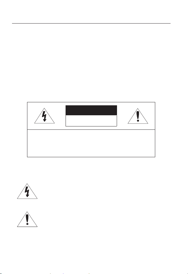
WARNING
TO REDUCE THE RISK OF FIRE OR ELECTRIC SHOCK, DO NOT EXPOSE
THIS PRODUCT TO RAIN OR MOISTURE. DO NOT INSERT ANY METALLIC
OBJECT THROUGH THE VENTILATION GRILLS OR OTHER OPENNINGS
ON THE EQUIPMENT.
Apparatus shall not be exposed to dripping or splashing and that no objects
filled with liquids, such as vases, shall be placed on the apparatus.
To prevent injury, this apparatus must be securely attached to the Wall/ceiling
in accordance with the installation instructions.
CAUTION
CAUTION
RISK OF ELECTRIC SHOCK.
DO NOT OPEN
CAUTION
REFER SERVICING TO QUALIFIED SERVICE PERSONNEL.
: TO REDUCE THE RISK OF ELECTRIC SHOCK.
DO NOT REMOVE COVER (OR BACK).
NO USER SERVICEABLE PARTS INSIDE.
EXPLANATION OF GRAPHICAL SYMBOLS
The lightning flash with arrowhead symbol, within an
equilateral triangle, is intended to alert the user to the
presence of “dangerous voltage” within the product’s
enclosure that may be of sufficient magnitude to constitute a
risk of electric shock to persons.
The exclamation point within an equilateral triangle is intended
to alert the user to the presence of important operating
and maintenance (servicing) instructions in the literature
accompanying the product.
4_ overview

Class construction
An apparatus with CLASS construction shall be connected to a MAINS
socket outlet with a protective earthing connection.
Battery
Batteries(battery pack or batteries installed) shall not be exposed to excessive
heat such as sunshine, fire or the like.
Disconnection Device
Disconnect the main plug from the apparatus, if it’s defected. And please call
a repair man in your location.
When used outside of the U.S., it may be used HAR code with fittings of
an approved agency is employed.
CAUTION
Risk of explosion if battery is replaced by an incorrect type.
Dispose of used batteries according to the instructions.
These servicing instructions are for use by qualified service personnel only.
To reduce the risk of electric shock do not perform any servicing other than
that contained in the operating instructions unless you are qualified to do so.
The CVBS out terminal of the product is provided for easier installation, and is
not recommended for monitoring purposes.
Please use the input power with just one camera and other devices must not
be connected.
The ITE is to be connected only to PoE networks without routing to the
outside plant.
● OVERVIEW
English _5

overview
Please read the following recommended safety precautions carefully.
yDo not place this apparatus on an uneven surface.
yDo not install on a surface where it is exposed to direct sunlight, near
heating equipment or heavy cold area.
yDo not place this apparatus near conductive material.
yDo not attempt to service this apparatus yourself.
yDo not place a glass of water on the product.
yDo not install near any magnetic sources.
yDo not block any ventilation openings.
yDo not place heavy items on the product.
User’s Manual is a guidance book for how to use the products.
The meaning of the symbols are shown below.
yReference : In case of providing information for helping of product’s usages
yNotice : If there’s any possibility to occur any damages for the goods and
human caused by not following the instruction
Please read this manual for the safety before using of goods and keep it in
the safe place.
6_ overview

CONTENTS
OVERVIEW
3
INSTALLATION &
CONNECTION
21
NETWORK CONNECTION
AND SETUP
42
3 Important Safety Instructions
9 Product Features
10 Recommended PC Specifications
10 Recommended Micro SD/
SDHC/SDXC Memory Card
Specifications
11 What’s Included
14 At a Glance (SND-5084R)
18 At a Glance (SNV-5084R)
21 Installation (SND-5084R)
23 Installation (SNV-5084R)
32 Inserting/Removing a Micro SD
Memory Card (SND-5084R/SNV5084R)
34 Memory Card Information
(Not Included)
35 Connecting with other Device
42 Connecting the Camera Directly
to Local Area Networking
43 Connecting the Camera Directly
to a DHCP Based DSL/Cable
Modem
44 Connecting the Camera Directly
to a PPPoE Modem
45 Connecting the Camera to a
Broadband Router with the
PPPoE/Cable Modem
46 Buttons used in IP Installer
47 Static IP Setup
51 Dynamic IP Setup
52
Port Range Forward (Port Mapping)
Setup
54 Connecting to the Camera from a
Shared Local PC
54 Connecting to the Camera from a
Remote PC via the Internet
● OVERVIEW
English _7

overview
WEB VIEWER
55
SETUP SCREEN
72
APPENDIX
123
55 Connecting to the Camera
57 Password setting
57 Login
58 Installing Silverlight Runtime
61 Installing STW WebViewer Plugin
63 Using the Live Screen
66 Playing the recorded video
72 Setup
72 Video & Audio Setup
87 Network Setup
98 Event Setup
115 System Setup
123 Specification
128 Product Overview
130 Troubleshooting
132 Open Source Announcement
8_ overview

PRODUCT FEATURES
• Dustproof/Waterproof (IP66) (SNV-5084R)
The dustproof and waterproof design makes you feel at ease when installing the product
outdoors or exposing it to rain.
• IR mode
If the IR indicator turns on, the product switches to the IR mode for preventing an object
from being too bright, which helps you identify the object in near distance.
• Visibility: 30m (SND-5084R/SNV-5084R)
In B/W mode, the IR indicator turns on with the effective visibility of 30m at 0 Lux.
• HD Video Quality
• Multi-Streaming
This network camera can display videos in different resolutions and qualities
simultaneously using different CODECs.
• Web Browser-based Monitoring
Using the Internet web browser to display the image in a local network environment.
• Alarm
When an event occurs, video is either sent to the email address registered by the user, sent
to the FTP server, saved in a Micro SD card, or a signal is sent to the alert output terminal.
• Tampering Detection
Detects tempering attempts on video monitoring.
• Motion Detection
Detects motion from the camera’s video input.
• Intelligent Video Analysis
Analyzes video to detect logical events of specified conditions from the camera’s video
input.
• Face Detection
Detects faces from the camera’s video input.
• Audio Detection
Detects sound louder than a certain level specified by user.
• Auto Detection of Disconnected Network
Detects network disconnection before triggering an event.
• ONVIF Compliance
This product supports ONVIF Profile-S.
For more information, refer to www.onvif.org.
● OVERVIEW
English _9

overview
RECOMMENDED PC SPECIFICATIONS
• CPU : Intel Core 2 Duo 2.4 GHz or higher (for using 1920x1080 30 fps)
Intel Core i7 2.8 GHz or higher (for using 1920x1080 60 fps)
Web Plug-in is optimized to SSE 4.1 Instruction Set.
`
• Resolution : 1280X1024 pixels or higher (32 bit color)
• RAM : 2GB or higher
• Supported OS : Windows XP / VISTA / 7 / 8, MAC OS X 10.7
• Supported Browser : Microsoft Internet Explorer (Ver. 8~10)
Mozilla Firefox (Ver. 9~19), Google Chrome (Ver. 15~25),
Apple Safari (Ver. 6.0.2(Mac OS X 10.8, 10.7 only), 5.1.7)
Windows 8 is supported only in the Desktop mode.
`
Neither a beta test version unlike the version released in the company website nor the developer version will
`
be supported.
For IPv6 connection, Window 7 or higher is recommended.
`
For Mac OS X, only the Safari browser is supported.
`
• Video Memory : 256MB or higher
If the driver of the video graphic adapter is not installed properly or is not the latest version, the
`
J
video may not be played properly.
For a multi-monitoring system involving at least 2 monitors, the playback performance can be
`
deteriorated depending on the system.
RECOMMENDED MICRO SD/SDHC/SDXC MEMORY CARD
SPECIFICATIONS
• Recommended capacity : 4GB ~ 64GB
• For your camera, we recommend you use a memory card from the following manufacturers:
Micro SD/SDHC/SDXC Memory Card : Sandisk, Transcend
• For the framerate below 30 fps, it is recommended to use the specification memory card
of Class 6 or higher.
• For the framerate over 31 fps, it is recommended to use the specification memory card of
Class 10 UHS or higher.
10_ overview
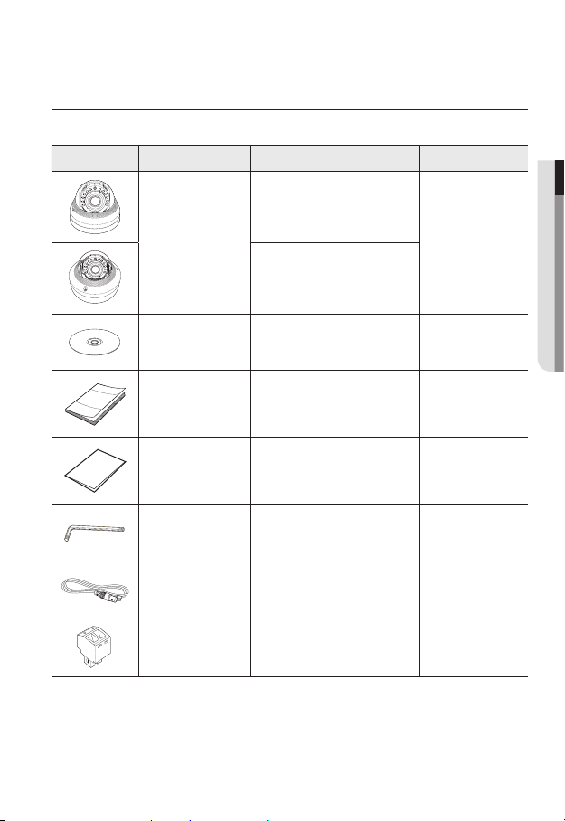
WHAT’S INCLUDED
Please check if your camera and accessories are all included in the product package.
Appearance Item Name
Camera
+ -
+ -
+ -
AC 24V / DC 12V
AC 24V / DC 12V
AC 24V / DC 12V
T
F
N
T
T
RESET
F
F
W
VIDEO
AF
N
N
RESET
RESET
W
W
VIDEO
VIDEO
AF
AF
Quantity
1
1
Description Model Name
SND-5084R or
SNV-5084R
● OVERVIEW
Instruction book,
Installer S/W CD
Quick Guide
(Optional)
Warranty card
(Optional)
1
1
1
Used to control the direction of
L Wrench
the camera / Used to remove and
1
replace the dome cover
Cable for the testing
monitor
Used to test the camera
1
connection to a portable display
device
Power Terminal Block 1 Plugged in the power plug
SND-5084R/
SNV-5084R
SND-5084R/
SNV-5084R
SND-5084R/
SNV-5084R
SND-5084R/
SNV-5084R
SND-5084R/
SNV-5084R
SND-5084R/
SNV-5084R
English _11
overview
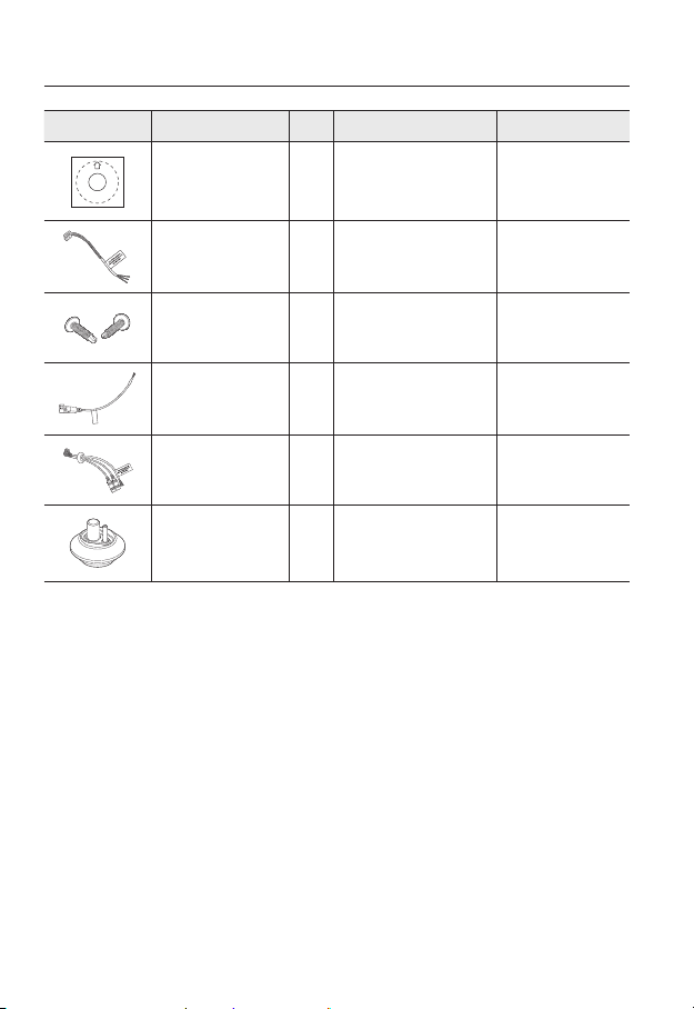
Appearance Item Name
Template
Alarm Cable 1 Useful for alarm connection SND-5084R
Tapping Screw
CAUTION: Be ware of the
Rated Voltage and Polarity
of the power connection.
Power Cable
Audio/alarm cable
Cable bush 1
Quantity
1
2
1
1
Description Model Name
Product installation guide
Useful for installation on the
ceiling, wall, etc.
Used to plug into the power port
Used to connect with the
audio and alarm port
Used to connect the LAN cable
with a diameter of Ø7~8.5.
SND-5084R/
SNV-5084R
SND-5084R
SNV-5084R
SNV-5084R
SNV-5084R
12_ overview
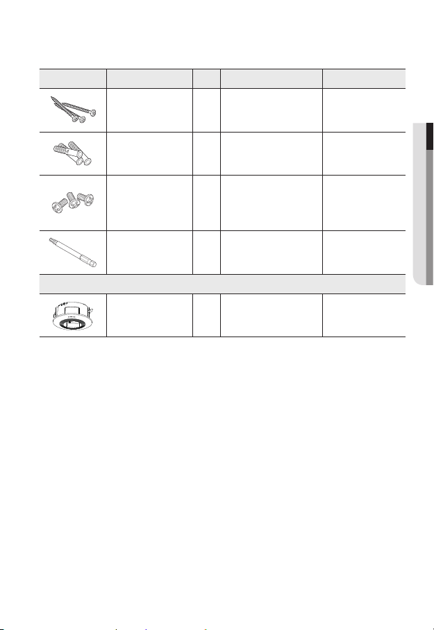
Appearance Item Name
Quantity
Description Model Name
Tapping Screw
Plastic Anchor
Machine Screws 3
Drill bit 1
Indoor Buried Housing
Used for installation on the
3
wall or ceiling
For fixing a screw,
3
Inserted in a hole
(reinforced anchoring force)
Used for assembling the dome
case when installing the product
on the pipe, wall mount, etc. or
blocking a hole.
Used for dome cover
disassembly, assembly and
camera installation.
Options (not included)
Housing for installing indoor
buried type cameras
SNV-5084R
● OVERVIEW
SNV-5084R
SNV-5084R
SNV-5084R
SND-5084R/
SNV-5084R
English _13
overview
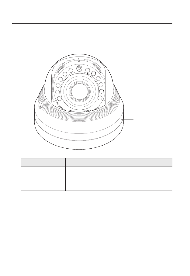
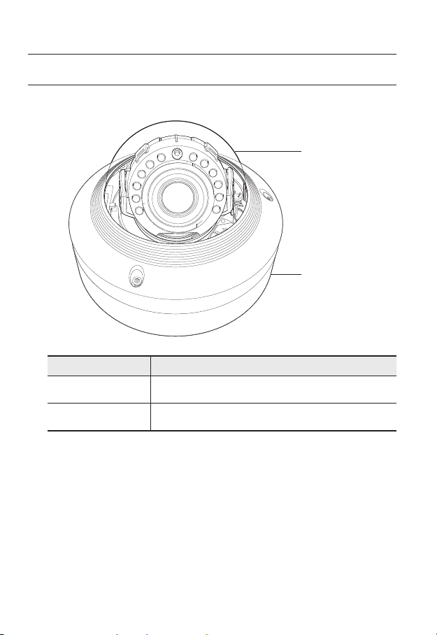
AT A GLANCE (SND-5084R)
Appearance
Item Description
a
Dome cover
Case cover used to protect the lens and the main unit.
a
b
Camera Case
b
14_ overview
Housing part that covers the camera body.
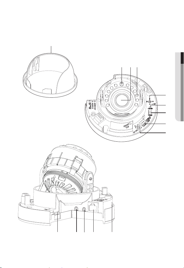
Components
a
● OVERVIEW
cdb
e
f
g
h
i
OUT
IN
AUDIO
AUDIO
klm nj
English _15

overview
Item Description
Internal Cover It is a cover to protect the main body.
a
Illumination Sensor Detects incoming light to control the IR LED.
b
Lens Lens for the camera.
c
IR LED These infrared LED’s are controlled by the illumination sensor.
d
Zoom/Focus Control
e
Button
Reset Button
f
Test Monitor Out
g
Alarm I/O Port
h
T Zoom in (Tele)
W Zoom out (Wide)
N Focusing on a near object (Near)
F Focusing on a far object (Far)
Focus Control Press this button for automatic focus control.
The button restores all camera settings to the factory default.
Press and hold for about 5 seconds to reboot the system.
If you reset the camera, the network settings will be adjusted so that
J
DHCP can be enabled. If there is no DHCP server in the network, you
must run the IP Installer program to change the basic network settings
such as IP address, Subnet mask, Gateway, etc., before you can
connect to the network.
Output port for test monitoring the video output. Use the test monitor cable
to connect to a mobile display and check the test video.
ALARM IN
ALARM OUT Used to connect the alarm output signal.
GND Common port for alarm output signal.
Used to connect the alarm input sensor or external day/
night sensor.
Power Port Port for power terminal block.
i
16_ overview
Item Description
Micro SD Memory
j
Card Compartment
Audio Out Jack Used to connect to speakers.
k
Audio In Jack Used to connect to a microphone.
l
Network Port Used to connect the PoE or Ethernet cable for network connection.
m
Microphone hole A microphone is embedded.
n
Compartment for the Micro SD memory card.
● OVERVIEW
English _17
overview
AT A GLANCE (SNV-5084R)
Appearance
+ -
+ -
+ -
AC 24V / DC 12V
AC 24V / DC 12V
AC 24V / DC 12V
VIDEO
VIDEO
VIDEO
Item Description
a
Dome cover
Case cover used to protect the lens and the main unit.
a
T
F
N
T
T
RESET
F
F
W
AF
N
N
RESET
RESET
W
W
AF
AF
b
Camera Case
b
18_ overview
Housing part that covers the camera body.
Components
a cb
+ -
AC 24V / DC 12V
RESET
VIDEO
d efg
● OVERVIEW
T
F
N
W
AF
h ji
English _19

overview
Item Description
Illumination Sensor Detects incoming light to control the IR LED.
a
Lens Lens for the camera.
b
IR LED These infrared LED’s are controlled by the illumination sensor.
c
Power Port Port for power terminal block.
d
Test Monitor Out
e
Reset Button
f
Zoom/Focus Control
g
Button
Micro SD Memory
h
Card Compartment
Audio and alarm
i
cable port
Output port for test monitoring the video output. Use the test monitor cable
to connect to a mobile display and check the test video.
The button restores all camera settings to the factory default.
Press and hold for about 5 seconds to reboot the system.
If you reset the camera, the network settings will be adjusted so that
J
DHCP can be enabled. If there is no DHCP server in the network, you
must run the IP Installer program to change the basic network settings
such as IP address, Subnet mask, Gateway, etc., before you can
connect to the network.
T Zoom in (Tele)
W Zoom out (Wide)
N Focusing on a near object (Near)
F Focusing on a far object (Far)
Focus Control Press this button for automatic focus control.
Compartment for the Micro SD memory card.
Plug in the audio and alarm cable to this port to connect with external alarm
device/microphone/speaker.
Network Port Used to connect the PoE or Ethernet cable for network connection.
j
20_ overview
installation & connection
INSTALLATION (SND-5084R)
Precautions before installation
Ensure you read out the following instructions before installing the camera:
• It must be installed on the area (ceiling or wall) that can withstand 5 times the weight
of the camera including the installation bracket.
• Stuck-in or peeled-off cables can cause damage to the product or a fire.
• For safety purposes, keep anyone else away from the installation site.
And put aside personal belongings from the site, just in case.
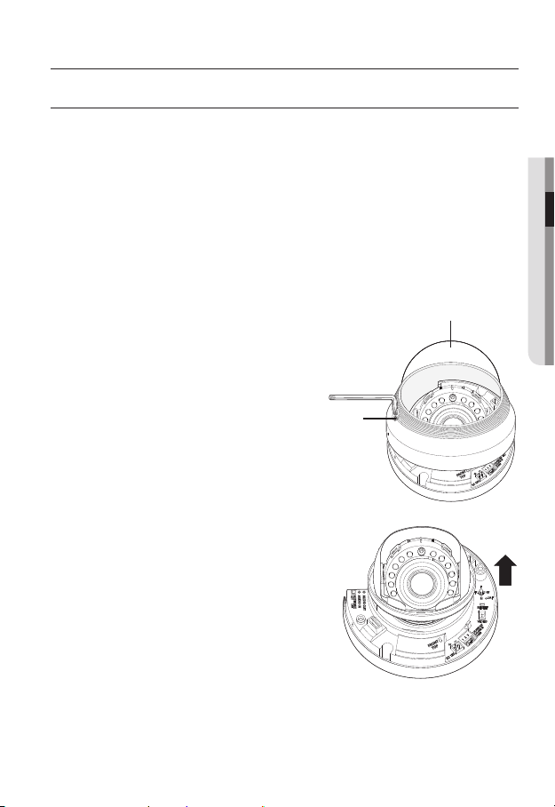
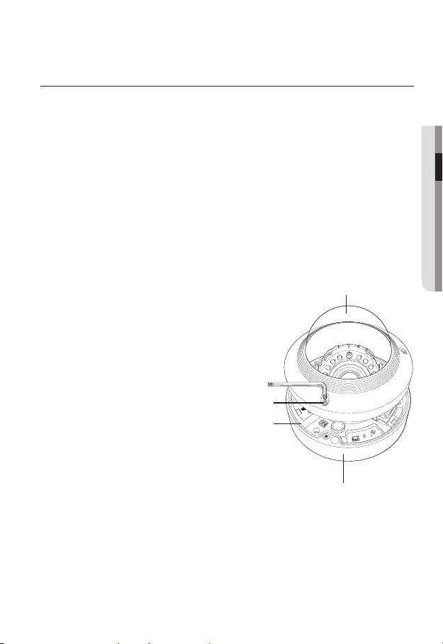
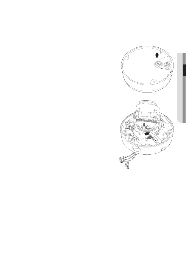
Disassembling
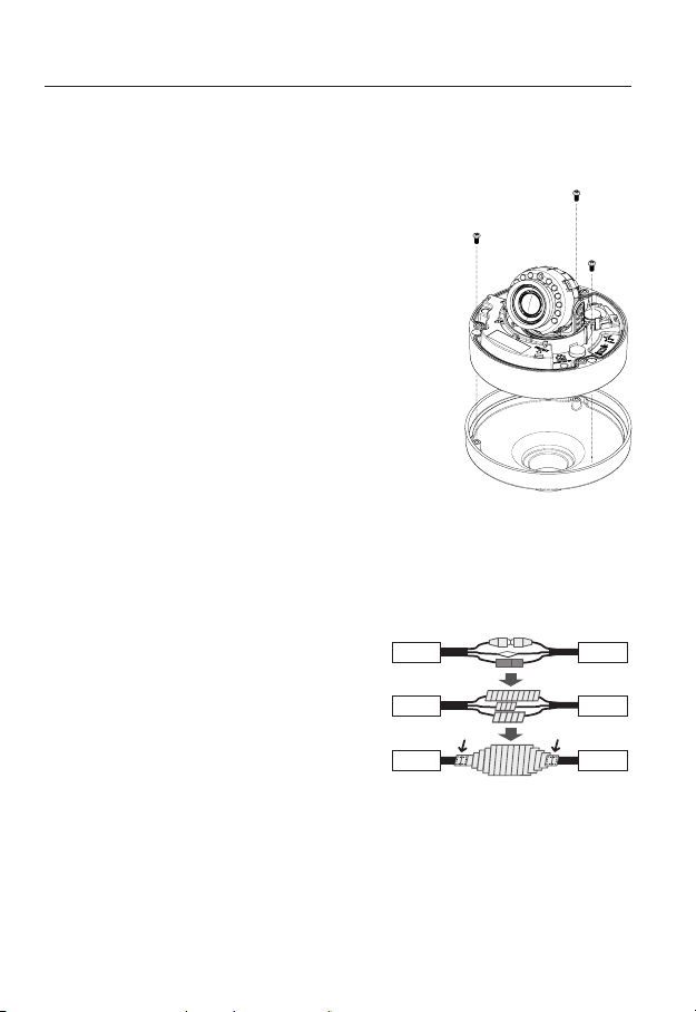
1. With the provided L-wrench, loosen
2 bolts on the dome cover counter
clockwise to remove the cover.
Bolts
2. Lift up the inner cover to separate it.
Dome cover
● INSTALLATION & CONNECTION
English _21
installation & connection
Installation
1. Attach the installation template to the
selected area and punch 3 holes as shown in
the figure.
2. Use the 2 supplied screws to fix the camera
to the 2 punched holes.
Set the <FRONT TOP> mark imprinted on the
`
camera to face the direction of camera monitoring.
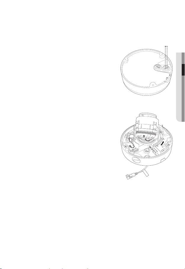
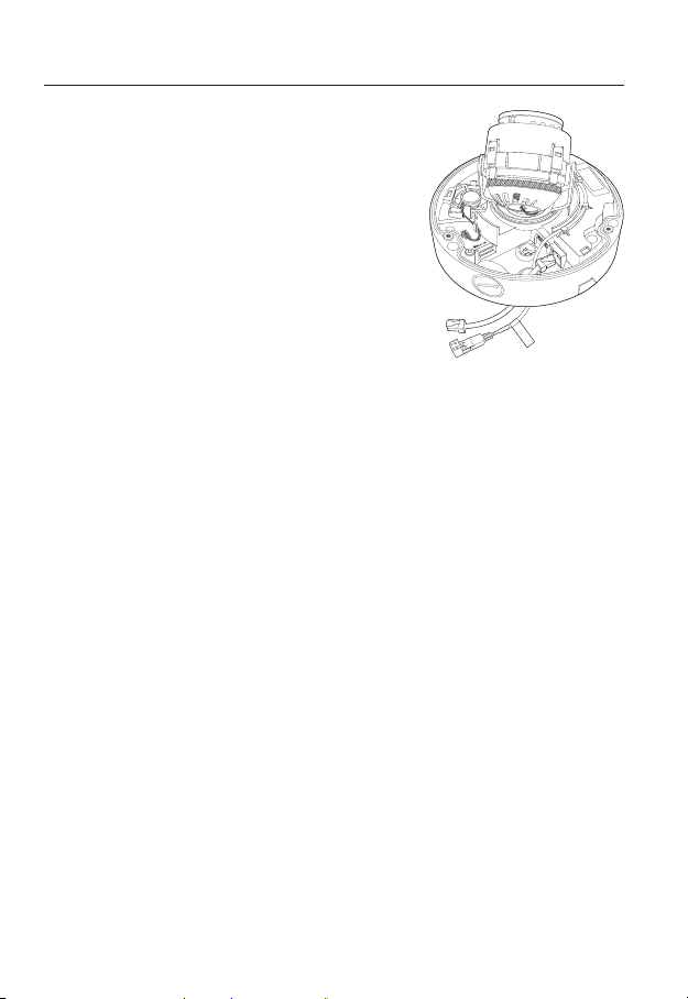
3. Connect the camera internal terminal with the
corresponding cable.
4.
Adjust the lens in a desired direction by
referring to the “Adjusting the monitoring
direction for the camera” section. (page 31)
5. Use the L wrench to assemble the dome
cover.
Pay attention to the direction for assembly.
`
J
22_ installation & connection
INSTALLATION (SNV-5084R)
This camera is waterproof and in compliance with the IP66 spec, but the jack connected to the
`
J
external cable is not. You are recommended to install this product below the edge of eaves to
prevent the cable from being externally exposed.
Precautions before installation
Ensure you read out the following instructions before installing the camera:
• It must be installed on the area (ceiling or wall) that can withstand 5 times the weight
of the camera including the installation bracket.
• Stuck-in or peeled-off cables can cause damage to the product or a fire.
• For safety purposes, keep anyone else away from the installation site.
And put aside personal belongings from the site, just in case.
Disassembling
1. With the provided L-wrench and
drill bit, loosen 3 bolts on the dome
cover counter clockwise to remove
the cover.
Dome cover
● INSTALLATION & CONNECTION
Bolts
Camera Body
+ -
AC 24V / DC 12V
Camera Case
T
F
N
RESET
W
VIDEO
AF
English _23

installation & connection
AC 24V / DC 12V
RESET
VIDEO
F
W
AF
T
N
+ -
AC 24V / DC 12V
RESET
VIDEO
F
W
AF
T
N
+ -
Installation
1. Using the template provided as an
accessory, drill the screw installation
hole(diameter of 6mm, minimal depth of
55mm) and firmly insert the plastic anchor
provided as an accessory to the end.
2. Fit the bottom hole to the anchor hole and
insert and fix the taping screw (M4.5xL50).
3. Connect and arrange the necessary cables
lest that they should be damaged or twisted
while installing the camera.
4. Adjust the lens in a desired direction by referring to the “Adjusting the monitoring
direction for the camera” section. (page 31)
5. Close the dome cover.
`To ensure waterproofing, tight up the fixing bolts using the L-wrench and drill bit.
AF
AF
AF
VIDEO
VIDEO
VIDEO
W
W
W
RESET
RESET
RESET
N
N
N
F
F
F
T
T
T
AC 24V / DC 12V
AC 24V / DC 12V
AC 24V / DC 12V
+ -
+ -
+ -
24_ installation & connection
Connecting waterproof power cable and LAN cable
1. Remove the dome cover and the case.
2. Pull out the long projected part of the rubber plug on
the bottom and remove it as shown in the figure.
Use an appropriate cable bush for the LAN cable to be
`
J
connected.
- Basic camera : Use the cable with a diameter of Ø5~6.5.
- Components provided : Use the cable with a diameter of
Ø7~8.5.
3. Insert the power cable into the small hole made by
removing the projected part of the rubber plug in step
2 above, and lay the cable along the long groove.
4. Connect the power cable with the power terminal
block.
● INSTALLATION & CONNECTION
CAUTION: Be ware o f the
Rated Voltage and P olari ty
of the power conne ction .
English _25
installation & connection
5. Insert the LAN cable into the large hole made by
removing the projected part of the rubber plug in step
2 above.
6. Remove the sheath with a cable cutter, and align the
cables.
7. Connect the LAN cable with a LAN connector, and
insert it into the LAN tool.
8. Connect the finished cable to the Ethernet port.
CAUTION: Be ware o f the
Rated Voltage and P olari ty
of the power conne ction .
26_ installation & connection
Connecting alarm cable
1. Remove the dome cover and the case.
2. Pull out the rubber plug on the bottom as shown in
the figure.
3. Insert the alarm cable into the hole made by
removing the rubber plug in step 2, and connect the
cable with the PCB alarm terminal.
4. Align the cable so that it should not be damaged or
jammed when installing the camera.
5. Put the rubber plug of the alarm cable into the hole.
6. Adjust the lens in a desired direction by referring to
the “Adjusting the monitoring direction for the
camera” section.
7. Attach the dome cover.
(page 31)
● INSTALLATION & CONNECTION
English _27
installation & connection
Attaching to the unbundled adapter
Choose and purchase a necessary one of the following options (unbundled) that is suitable
to the installation site or for your convenience.
1. Remove the dome cover from the case by referring to
the “Disassembling” section. (page 23)
2. Use the provided machine screw to fix the camera
case to the unbundled adapter.
3. Connect and arrange the necessary cables lest that
they should be damaged or twisted while installing the
camera.
4. Install the camera body in the reverse order of
“Disassembling”.
5. Adjust the lens in a desired direction by referring to the
“Adjusting the monitoring direction for the camera”
section. (page 31)
6. Close the dome cover.
`To ensure waterproofing, tight up the fixing bolts using the
L-wrench and drill bit.
Outdoor installation
When you install it outside of the building, please waterproof it with waterproof butyl rubber
tape (can be purchased in stores) so that water does not leak from the gap of the cable
connected to the outside.
1. Connect the power, I/O, BNC, and LAN
cables.
2. Wrap the black cable jacket (Area A) and the
cable connection area with waterproof (butyl
rubber) tape so that more than half of the
butyl rubber tape is overlapped.
If the cable jacket is not waterproofed properly,
`
J
then it can directly cause leakage. Make sure to
protect the cable with a dense layer of taping.
Waterproof butyl tape is made of butyl rubber that can be stretched to twice its normal length.
`
Camera
Camera
AA
Camera
System
System
System
28_ installation & connection
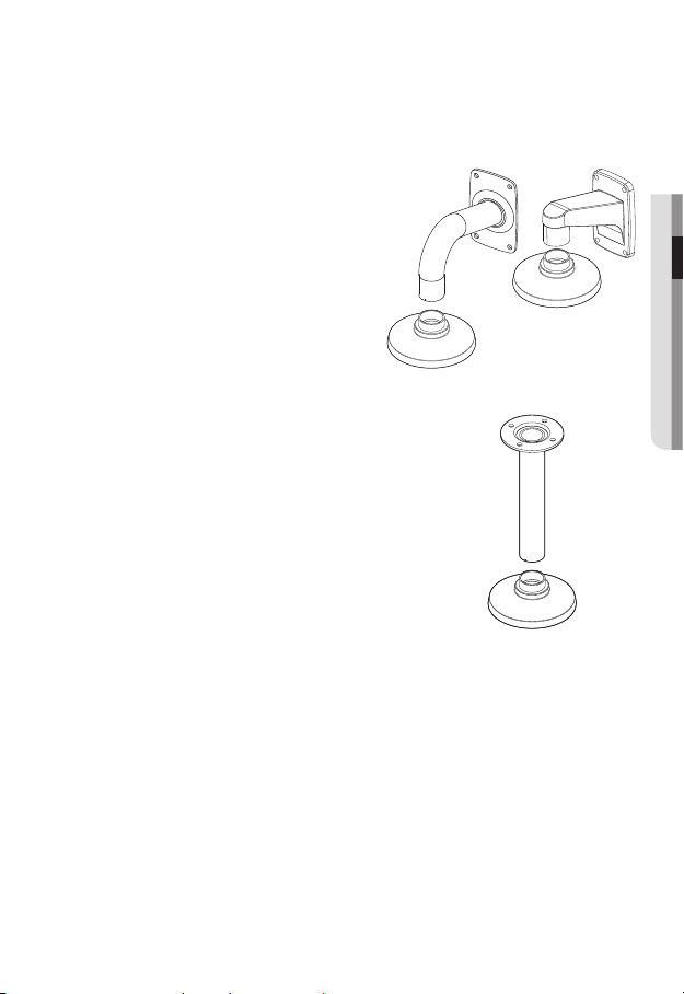
Optional Accessories for Installation
For your easier installation, you can purchase appropriate optional accessories available.
1. WALL MOUNT ADAPTOR(SBP-300WM or
SBP-300WM1)/HANGING MOUNT
(SBP-301HM2 : SND-5084R,
SBP-300HM6 : SNV-5084R)
This adaptor is used when installing the
dome camera onto a wall.
2. CEILING MOUNT ADAPTOR(SBP-300CM)/
HANGING MOUNT(SBP-301HM2 : SND-5084R,
SBP-300HM6 : SNV-5084R)
This adaptor is used when installing the dome
camera on a concrete ceiling.
● INSTALLATION & CONNECTION
English _29
installation & connection
3. POLE MOUNT ADAPTOR(SBP-300PM)
This is an adaptor for WALL MOUNT ADAPTOR
(SBP-300WM or SBP-300WM1) installation on a
pole whose diameter is bigger than 80mm.
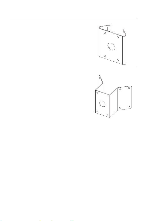
4. CORNER MOUNT ADAPTOR (SBP-300KM)
This is an adaptor for WALL MOUNT ADAPTOR
(SBP-300WM or SBP-300WM1) installation on
the corner of wall joint.
30_ installation & connection
 Loading...