


ENGLISH
Document No. CSD-SMESAR3
Revision 01
Copyright SAMSUNG MEDISON Co., LTD.
Safety Requirements
Classifications:
-Type of protection against electrical shock: Class I
-Degree of protection against electrical shock (Patient connection):Type BF equipment
-Degree of protection against harmful ingress of water: Ordinary equipment
-Degree of safety of application in the presence of a flammable anesthetic material with air or with oxygen or nitrous oxide: Equipment not suitable for use in the presence of a flammable anesthetic mixture with air or with oxygen or nitrous oxide.
-Mode of operation: Continuous operation
Electromechanical safety standards met:
-IEC/EN 60601-1 Medical Electrical Equipment, Part 1General Requirements for Safety.
-IEC/EN 60601-1-1 Safety requirements for medical electrical systems.
-IEC/EN 60601-1-2 Electromagnetic compatibility -Requirements and tests.
-IEC/EN 60601-2-37 Particular requirements for the safety of ultrasonic medical diagnostic and monitoring equipment.
-IEC 61157 Declaration of acoustic output parameters.
-ISO 10993-1 Biological evaluation of medical devices.
-UL 60601-1 Medical Electrical Equipment, Part 1 General Requirements for Safety.
-CSA 22.2, 601.1 Medical Electrical Equipment, Part 1 General Requirements for Safety.

Declarations:
This is CSA symbol for Canada and United States of America
This is manufacturer’s declaration of product compliance 0123 with applicable EEC directive(s) and the European notified
body.
This is manufacturer’s declaration of product compliance with applicable EEC directive(s).
This is GMP symbol for Good Manufacturing Practice of
Korea quality system regulation.

READ THIS FIRST
Before asking for the product to be repaired, read this service manual thoroughly, learn how to troubleshoot, and make sure you understand the precautions fully.
The repair of the system and the replacement of parts must be carried out by an authorized dealer or the customer service department of SAMSUNG MEDISON Co., Ltd.
The company is shall not be held liable for any injury and damage caused by not following this warning.
For safe use of this product, you should read ‘Chapter 2. Safety’ in this manual, prior to starting to
useing this system.
DANGER˙ ˙ ˙ ˙ ˙ ˙
Describes precautions necessary to prevent user hazards of great urgency. Ignoring a DANGER warning will risk life-threatening injury.
˙ ˙ ˙ ˙˙˙ ˙
WARNING
Used to indicate the presence of a hazard that can cause serious personal injury, or substantial property damage.
˙ ˙ ˙ ˙˙˙ ˙
CAUTION
Indicates the presence of a hazard that can cause equipment damage.
NOTE˙ ˙ ˙ ˙
A piece of information useful for installing, operating and maintaining a system. Not related to any hazard.

Contents
Chapter 1. General Information |
|
||
1.1 |
Overview |
....................................................................................................... |
1-1 |
1.2 |
FeaturesandAdvantagesofSonoAceR3.................................................. |
1-2 |
|
1.3 |
ProductConfiguration.................................................................................... |
1-3 |
|
|
1.3.1 |
Console......................................................................................... |
1-3 |
|
1.3.2 |
LCDMonitor................................................................................. |
1-4 |
|
1.3.3 |
ControlPanel................................................................................ |
1-5 |
|
1.3.4 |
Probe............................................................................................ |
1-5 |
1.4 |
Specifications.................................................................................................. |
1-6 |
|
Chapter 2. Safety |
|
|
|
2.1 |
Overview |
....................................................................................................... |
2-1 |
2.2 |
Safety-RelatedInformation............................................................................ |
2-2 |
|
|
2.2.1 |
SafetySymbols............................................................................ |
2-2 |
|
2.2.2 |
LABEL........................................................................................... |
2-3 |
2.3 |
ElectricalSafety.............................................................................................. |
2-4 |
|
|
2.3.1 |
Prevention ElectricShock........................................................... |
2-4 |
|
2.3.2 |
ESD............................................................................................... |
2-4 |
|
2.3.3 |
EMI................................................................................................ |
2-5 |
|
2.3.4 |
EMC.............................................................................................. |
2-5 |
2.4 |
MechanicalSafety.......................................................................................... |
2-11 |
|
|
2.4.1 |
MovingEquipment....................................................................... |
2-11 |
|
2.4.2 |
SafetyNote................................................................................... |
2-11 |
2.5 |
BiologicalSafety............................................................................................. |
2-12 |
|
|
2.5.1 |
ALARAPrinciple.......................................................................... |
2-12 |
2.6 |
EnvironmentalProtection.............................................................................. |
2-24 |
|

Contents
Chapter 3. Installing the Product |
|
||
3.1 |
Overview |
....................................................................................................... |
3-1 |
3.2 |
Transportation................................................................................................ |
3-3 |
|
|
3.2.1 |
PrecautionsforTransportation.................................................... |
3-3 |
|
3.2.2 |
TemperatureandHumidity......................................................... |
3-3 |
3.3 |
Unpacking |
....................................................................................................... |
3-4 |
|
3.3.1 |
UnpackingtheBox....................................................................... |
3-4 |
|
3.3.2 |
CheckingPackagecontents....................................................... |
3-5 |
3.4 |
PrecautionsforInstallation............................................................................ |
3-6 |
|
|
3.4.1 |
Precautions................................................................................... |
3-6 |
3.5 |
InstallationsProcedure.................................................................................. |
3-7 |
|
|
3.5.1 |
InstallationSafety......................................................................... |
3-7 |
|
3.5.2 |
ConnectingthePowerCord........................................................ |
3-8 |
|
3.5.3 |
ConnectingtheNetworkCable................................................... |
3-9 |
|
3.5.4 |
ConnectingtheProbe.................................................................. |
3-9 |
3.6 |
StartingtheProduct....................................................................................... |
3-10 |
|
3.7 |
ShuttingdowntheProduct............................................................................ |
3-11 |
|
3.8 |
ConnectingthePeripherals........................................................................... |
3-12 |
|
|
3.8.1 |
ExternalPeripherals.................................................................... |
3-12 |
3.9 |
SystemSetting............................................................................................... |
3-14 |
|
|
3.9.1 |
General SystemSetup................................................................ |
3-14 |
|
3.9.2 |
DisplaySetup............................................................................... |
3-16 |
|
3.9.3 |
Misc............................................................................................... |
3-18 |
3.10 |
MeasureSetting............................................................................................. |
3-19 |
|
|
3.10.1 |
General......................................................................................... |
3-19 |
|
3.10.2 |
Doppler......................................................................................... |
3-20 |
|
3.10.3 |
Report........................................................................................... |
3-21 |
|
3.10.4 |
OB................................................................................................. |
3-22 |
|
3.10.5 |
FetalEcho.................................................................................... |
3-25 |
|
3.10.6 |
Cardiac.......................................................................................... |
3-26 |
|
3.10.7 |
Urology.......................................................................................... |
3-26 |
|
3.10.8 |
Vascular........................................................................................ |
3-27 |
3.11 |
SettingDICOM(Optional)............................................................................ |
3-28 |
|
|
3.11.1 |
SettingDICOMInformation......................................................... |
3-28 |
|
3.11.2 |
NetworkSetup.............................................................................. |
3-29 |
|
3.11.3 |
AddingorChangingtheDICOMServer.................................... |
3-29 |
|
3.11.4 |
EditingtheDICOMServer........................................................... |
3-32 |
|
3.11.5 |
DeletingDICOMServer............................................................... |
3-32 |

|
3.11.6 |
TestingDICOMServer................................................................ |
3-32 |
|
3.11.7 |
DICOMLog.................................................................................. |
3-32 |
3.12 |
SettingOption................................................................................................. |
3-34 |
|
3.13 |
SettingPeripheralDevices............................................................................ |
3-35 |
|
|
3.13.1 |
VideoOutType............................................................................ |
3-35 |
|
3.13.2 |
FootSwitch................................................................................... |
3-35 |
|
3.13.3 |
Printer1........................................................................................ |
3-35 |
|
3.13.4 |
Printer2........................................................................................ |
3-35 |
3.14 |
Information...................................................................................................... |
3-36 |
|

Contents
Chapter 4. Checking the Product |
|
||
4.1 |
Overview |
..................................................................................................... |
4-1 |
4.2 |
StartingtheProduct....................................................................................... |
4-2 |
|
4.3 |
Monitor |
....................................................................................................... |
4-3 |
|
4.3.1 |
MonitorDisplay............................................................................ |
4-3 |
4.4 |
ControlPanel.................................................................................................. |
4-5 |
|
|
4.4.1 |
DetailControlPanel..................................................................... |
4-6 |
|
4.4.2 |
SoftMenu..................................................................................... |
4-8 |
|
4.4.3 |
Keyboards.................................................................................... |
4-9 |
4.5 |
CheckingthePerformance .......................................................................... |
4-11 |
|
|
4.5.1 |
BasicCheck................................................................................. |
4-11 |
|
4.5.2 |
DetailCheck................................................................................. |
4-12 |

Contents
5 |
|
|
|
5.1 |
|
5-1 |
|
5.2 |
SystemBlockDiagram.................................................................................. |
5-3 |
|
5.3 |
EKO7 ........................................................................................ |
5-4 |
|
|
5.3.1 |
............................................................................................... |
5-4 |
|
5.3.2 |
UltrasoundSystemPart.............................................................. |
5-4 |
|
5.3.3 |
PCPart......................................................................................... |
5-5 |
|
5.3.4 |
UserInterfacePart....................................................................... |
5-5 |
|
5.3.5 |
ACtoDC PowerModule............................................................. |
5-5 |
5.4 |
PSA |
5-6 |
|
5.5 |
BeamformerBoard......................................................................................... |
5-8 |
|
5.6CWBoard5-11
5.7 |
BackEndBoard............................................................................................. |
5-14 |
5.8PCIBoard5-18
5.9DVIBoard5-19
5.10VGACard5-21
5.11 |
VCRINBoard.................................................................................................. |
5-22 |
5.12 |
PCMotherBoard........................................................................................... |
5-23 |
5.13 |
SoftwareDSC................................................................................................. |
5-24 |
5.14 |
LCDIFBoard.................................................................................................. |
5-26 |
5.15 |
RearBoard..................................................................................................... |
5-27 |
5.16 |
ControlPanel.................................................................................................. |
5-28 |
5.17 |
PowerSupply................................................................................................. |
5-30 |
Contents
Chapter 6. Basic Maintenance |
|
||
6.1 |
Overview |
....................................................................................................... |
6-1 |
6.2 |
SystemInformation........................................................................................ |
6-2 |
|
6.3 |
AdminMode................................................................................................... |
6-3 |
|
|
6.3.1 |
Entering AdminMode.................................................................. |
6-3 |
|
6.3.2 |
AdminModeFunctions................................................................ |
6-4 |
6.4 |
Upgrade |
..................................................................................................... |
6-6 |
|
6.4.1 |
SoftwareUpgrade........................................................................ |
6-6 |
|
6.4.2 |
HardwareUpgrade...................................................................... |
6-9 |
6.5 |
Backup&Restore.......................................................................................... |
6-10 |
|
|
6.5.1 |
BackupUserSetting.................................................................... |
6-10 |
|
6.5.2 |
RestoreUserSetting................................................................... |
6-12 |
6.6 |
AddingandDeletingOptions......................................................................... |
6-14 |
|
|
6.6.1 |
Optiontype................................................................................... |
6-14 |
|
6.6.2 |
RegisteringOption....................................................................... |
6-14 |
6.7 |
ControlPanel.................................................................................................. |
6-16 |
|

Contents
Chapter 7. Troubleshooting |
|
||
7.1 |
Overview |
....................................................................................................... |
7-1 |
7.2 |
Power |
....................................................................................................... |
7-2 |
|
7.2.1 |
PowerFailure............................................................................... |
7-2 |
|
7.2.2 |
Powercannotturnedoff.............................................................. |
7-2 |
|
7.2.3 |
Powerisautomaticallyturnedoff................................................ |
7-2 |
7.3 |
Monitro |
....................................................................................................... |
7-3 |
|
7.3.1 |
BlankScreen................................................................................ |
7-3 |
|
7.3.2 |
ScreenColorAbnomal................................................................ |
7-3 |
7.4 |
ErrorMessages.............................................................................................. |
7-4 |
|
|
7.4.1 |
Systemhangsafteranerrorduringbooting............................... |
7-4 |
|
7.4.2 |
Systemworkseveniferroroccurred.......................................... |
7-4 |
7.5 |
Image |
....................................................................................................... |
7-5 |
|
7.5.1 NoBWImageEcho&NoBWModeImageFormat......................... |
7-5 |
|
|
7.5.2 NoiseLinkRainovertheBWModeImage(Noise)........................... |
7-5 |
|
|
7.5.3 PW&ColorDopplerModeTrouble................................................... |
7-5 |
|

Contents
Chapter 8. Disassembly and Reassembly |
|
||
8.1 |
Overview |
....................................................................................................... |
8-1 |
8.2 |
Disassembly and Reassembly of the Body Cover ...................................... |
8-3 |
|
|
8.2.1 |
Preparations................................................................................. |
8-3 |
|
8.2.2 |
BodyRear&MiddleCover......................................................... |
8-3 |
|
8.2.3 |
Disassembly of the Main Part and LCD/Control Panel............. |
8-4 |
8.3 |
Disassembly and Reassembly of the Main System Part............................ |
8-5 |
|
|
8.3.1 |
Preparations................................................................................. |
8-5 |
|
8.3.2 |
Power&HDD&SideFan........................................................... |
8-5 |
|
8.3.3 |
PSA&Rear&RearFan&Handle............................................. |
8-6 |
|
8.3.4 |
LCD&Inverter&USBBoard...................................................... |
8-7 |
8.4 |
Disassembly and Reassembly of the Control Panel ................................... |
8-8 |
|
|
8.4.1 |
Preparations................................................................................. |
8-8 |
|
8.4.2 |
Disassembly Control Panel and LCD......................................... |
8-8 |
|
8.4.3 |
ControlPanel................................................................................ |
8-9 |

Contents
Chapter 9. Probe |
|
|
|
9.1 |
Overview |
....................................................................................................... |
9-1 |
9.2 |
ProbeList |
....................................................................................................... |
9-2 |
9.3 |
ThermalIndex(TITable)............................................................................... |
9-5 |
|
9.4 |
UltrasoundTransmissionGel........................................................................ |
9-6 |
|
9.5 |
Sheaths |
....................................................................................................... |
9-7 |
9.6 |
ProbePrecautions.......................................................................................... |
9-9 |
|
Chapter 10. User Maintenance |
|
||
10.1 |
Overview |
....................................................................................................... |
10-1 |
10.2 |
SystemMaintenance..................................................................................... |
10-2 |
|
|
10.2.1 |
InstallationMaintenance.............................................................. |
10-2 |
|
10.2.2 |
CleaningandDisinfections.......................................................... |
10-2 |
|
10.2.3 |
FuseReplacement...................................................................... |
10-3 |
|
10.2.4 |
AccuracyCheck........................................................................... |
10-4 |
10.3 |
AdministrationofInformation......................................................................... |
10-5 |
|
|
10.3.1 |
UserSettingBack-up................................................................... |
10-5 |
|
10.3.2 |
PatientInformationBack-up........................................................ |
10-5 |
|
10.3.3 |
Software........................................................................................ |
10-5 |
Chapter 11. Service Part List |
|
||
11.1 |
Overview |
....................................................................................................... |
11-1 |
11.2 |
BodyCover..................................................................................................... |
11-2 |
|
11.3 |
UltrasoundSystemPart ............................................................................... |
11-4 |
|
11.4 |
LCDPart |
....................................................................................................... |
11-5 |
11.5 |
PCPart |
....................................................................................................... |
11-6 |
11.6 |
PowerPart...................................................................................................... |
11-8 |
|
11.7 |
UserInterfacePart......................................................................................... |
11-9 |
|
11.8 |
ETCPart |
................................................................................................. |
11-10 |
11.9 |
Options |
................................................................................................... |
11-11 |
11.10 |
Probes |
................................................................................................... |
11-12 |

Chapter 1. General Information
1.1Overview
Chapter 1 contains the information necessary to plan the Troubleshooting of SonoAceR3.
The SonoAceR3 is a high-resolution color ultrasound scanner with high penetration and a variety of measurement functions.
Contents
1.1 |
Overview |
.................................................................................................... |
1-1 |
1.2 |
Features ...............................................and Advantages of SonoAceR3 |
1-2 |
|
1.3 |
Product Configuration ............................................................................... |
1-3 |
|
|
1.3.1 .................................................................................... |
Console |
1-3 |
|
1.3.2 ............................................................................ |
LCD Monitor |
1-4 |
|
1.3.3 ........................................................................... |
Control Panel |
1-5 |
|
1.3.4 ...................................................................................... |
Probes |
1-5 |
1.4 |
Specifications............................................................................................. |
1-6 |
|
Chapter 1. General Information 1-1

1.2Features and Advantages of SonoAceR3
zHigh-end Digital Beamforming : The SonoAceR3 utilizes the newly developed Digital Beam forming technology.
zA variety of applications : The SonoAceR3 is optimized for use in a variety of ultrasound departments, cardiac, vascular, abdomen, Obsterics, Urology, Gynecology.
zVarious diagnostic Modes : 2D Mode, M Mode, Color Doppler Mode, Power Doppler Mode, PW Spectral Doppler Mode, etc.
zMeasurement and Report Functions : Besides the basic distance, area, circumference and volume measurement functions, the SonoAceR3 also provides application-specific measurement functions. The report function collates measurement data.
zReview of Scanned Images : The SonoAceR3 displays Cine images of 512 frames and loop images of 4096 lines.
zSonoViewTM : This is a total ultrasound image management system, which allows a user to archive, view and exchange documents.
zDigital Imaging and Communication in Medicine (DICOM) Function : This is used to archive, transmit and print DICOM images through a network.
zPeripheral/Accessory Connection : A variety of peripheral devices including VCRs and printers can be easily connected to the SonoAceR3.
Chapter 1. General Information 1-2
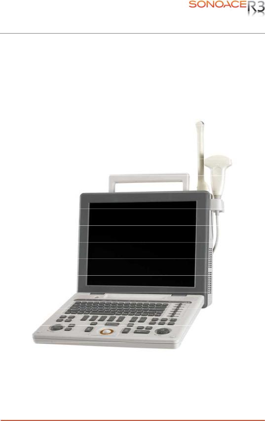
1.3Product Configuration
This Product consists of the monitor, the control panel, the console and, the probes and the cart(optional).
1.3.2Console
The console consists of two parts – the inner unit and the outer unit.
The interior of the console mainly contains devices that produce ultrasound images. The outside of the console consists of various connection ports and handles.
Handle 
 LCD Monitor
 Control Panel
[Figure 1-1] Console of SonoAce R3
Chapter 1. General Information 1-3

Probe Connector
[Figure 1-2] Front and Back of SonoAce R3
1.3.2LCD Monitor
The monitor of this system is a color VGA monitor, which displays ultrasound images and additional information. This monitor is connected to the main body through a central pivot, allowing it to be tilted to the optimal viewing angle.
[Figure 1-3] LCD Monitor
Chapter 1. General Information 1-4

1.3.3Control Panel
The control panel can be used for controlling the system.
Alpha-Numeric
Button
Dial Button
Track Ball 
Slide Volume
[Figure 1-4] Control Panel
1.3.4Probe
Probes are devices that generate ultrasound waves and process reflected wave data for the purpose of image formation.
NOT˙ ˙ ˙E˙
For more information, refer to ‘Chapter 9. Probes’.
Chapter 1. General Information 1-5
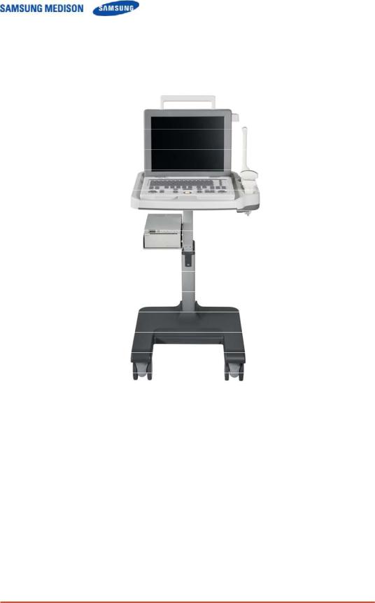
1.3.5SonoAceR3 Cart (Optional)
The SonoAce R3 System can be placed on a cart during use or for transport. For more information on installing and using the SonoAce R3, please refer to the installation guide that comes with it.
[Figure 1-5] SonoAce R3 Cart
Chapter 1. General Information 1-6
1.4Specifications
|
|
|
|
Height: 375mm (with handle) |
|
|
Physical Dimensions |
|
|
Width: 402mm (with probe holder) |
|
|
|
|
Depth: 188mm(with control panel) |
|
|
|
|
|
|
|
|
|
|
|
|
Weight: More than 8.7kg |
|
|
|
|
|
|
|
|
|
|
|
2D real-time |
|
|
|
|
|
Dual 2D real-time |
|
|
|
|
|
2D/M-mode |
|
|
Imaging modes |
|
Power Doppler |
||
|
|
Color Doppler for Option |
|||
|
|
|
|
||
|
|
|
|
Pulsed-wave Doppler for Option |
|
|
|
|
|
3D-mode (Freehand) for Option |
|
|
|
|
|
Simultaneous |
|
|
|
|
|
||
|
Gray Scale |
|
|
256 (8 bits) |
|
|
|
|
|
|
|
|
|
|
|
Dynamic transmit focusing, maximum of eight points (four points |
|
|
Focusing |
|
simultaneously selectable) |
||
|
|
|
|
Digital dynamic receive focusing (continuous) |
|
|
|
|
|
|
|
|
|
|
|
Curved Linear Array : C2-4/20, CN2-8, CN4-9 |
|
|
Probes |
|
|
Linear Array : L5-12/60, LN5-12/40 |
|
|
|
|
|
Endocavity Curved Linear Array : EC4-9 |
|
|
|
|
|
|
|
|
Probe connections |
|
One probe connectors |
||
|
|
Two probe connectors for option |
|||
|
|
|
|
||
|
|
|
|
||
|
Monitor |
|
|
15 inch LCD monitor |
|
|
|
|
|
|
|
|
|
|
|
USB 3ports |
|
|
|
|
|
LAN(10/100 BASE-T) |
|
|
Rear Panel |
|
DVI Output |
||
|
Input/Output |
|
BW Printer remote control |
||
|
Connections |
|
BW Output |
||
|
|
|
|
S-VHS Output |
|
|
|
|
|
Sound Output |
|
|
|
|
|
|
|
|
|
|
|
Maximum 512 frames for CINE memory |
|
|
Image Storage |
|
|
Maximum 4096 Lines for LOOP memory |
|
|
|
|
|
Image filing system |
|
|
|
|
|
|
|
|
|
|
|
Gynecology, Abdomen, OB, Renal, Urology, Vascular, Small |
|
|
Application |
|
Part, Fetal Heart, Breast, Musculoskeletal, Pediatric, Neonatal, |
||
|
|
|
|
Cardiac |
|
|
|
|
|
||
|
Electrical Parameters |
|
|
100-120V/200-240V, 250VA, 50/60Hz |
|
|
|
|
|
|
|
|
|
|
|
Chapter 1. General Information 1-7 |
|

|
|
|
|
Obssterics |
|
|
|
|
|
Gynecology |
|
|
Automatic Calculation |
|
Cardiology |
||
|
|
Fetal Echo |
|||
|
and Quantification |
|
|||
|
|
Vascular |
|||
|
|
|
|
||
|
|
|
|
Urology |
|
|
|
|
|
*Refer the Chapter 5 for additional information |
|
|
|
|
|
|
|
|
|
|
|
TGC control |
|
|
|
|
|
Mode-independent gain control |
|
|
|
|
|
Acoustic power control (adjustable) |
|
|
Signal processing |
|
|
Dynamic aperture |
|
|
|
|
Dynamic apodization |
|
|
|
(Pre-processing) |
|
|
|
|
|
|
|
Dynamic range control (adjustable) |
|
|
|
|
|
|
|
|
|
|
|
|
Image view area control |
|
|
|
|
|
M-mode sweep speed control |
|
|
|
|
|
HD zoom |
|
|
|
|
|
|
|
|
|
|
|
Frame average |
|
|
Signal processing |
|
Gamma-scale windowing |
||
|
(Post-processing) |
|
Image orientation (left/right and up/down, rotation) |
||
|
|
|
|
White on black/black on white |
|
|
|
|
|
|
|
|
|
|
|
Trackball operation of multiple cursors |
|
|
|
|
|
2D mode: Linear measurements and area measurements |
|
|
Measurement |
|
|
using elliptical approximation or trace |
|
|
|
|
|
M mode: Continuous readout of distance, time, and slope rate |
|
|
|
|
|
Doppler mode: Velocity and trace |
|
|
|
|
|
|
|
|
|
|
|
Black-and white printer |
|
|
|
|
|
Color printer |
|
|
Auxiliary |
|
VCR |
||
|
|
|
|
Monitor |
|
|
|
|
|
Foot switch |
|
|
User Interface |
|
|
English, German, French, Spanish, Italian, Russian, Chinese |
|
|
|
|
|
|
|
|
Pressure Limits |
|
Operating: 700hPa to 1060hPa |
||
|
|
Storage: 700hPa to 1060hPa |
|||
|
|
|
|
||
|
|
|
|
|
|
|
Humidity Limits |
|
|
Operating: 30% to 75% |
|
|
|
|
Storage & Shipping: 20% to 90% |
|
|
|
|
|
|
|
|
|
|
|
|
|
|
|
Temperature Limits |
|
Operating: 10 OC ~ 35OC |
||
|
|
Storage & Shipping: -25OC ~ 60OC |
|||
|
|
|
|
|
|
Chapter 1. General Information 1-8

Chapter 2. Safety
2.1Overview
Chapter 2 contains the information necessary to Safety
Please read this chapter before using the SAMSUNG MEDISON ultrasound system. It is relevant to the ultrasound system, the probes, the recording devices, and any of the optional equipment.
SonoAce R3 is intended for use by, or by the order of, and under the supervision of, a licensed physician who is qualified for direct use of the medical device.
Contents
2.1 |
Overview |
.................................................................................................... |
2-1 |
2.2 |
Safety –Related ....................................................................Information |
2-2 |
|
|
2.2.1 ....................................................................... |
Safety Symbols |
2-2 |
|
2.2.2 ...................................................................................... |
LABEL |
2-3 |
2.3 |
Electrical .........................................................................................Safety |
2-4 |
|
|
2.3.1 ...................................................... |
Prevention Electric Shock |
2-4 |
|
2.3.2 .......................................................................................... |
ESD |
2-4 |
|
2.3.3 ........................................................................................... |
EMI |
2-5 |
|
2.3.4 ......................................................................................... |
EMC |
2-5 |
2.4 |
Mechanical ...................................................................................Safety |
2-11 |
|
|
2.4.1 ................................................................ |
Moving Equipment |
2-11 |
|
2.4.2 ............................................................................ |
Safety Note |
2-11 |
2.5 |
Biological .....................................................................................Safety |
2-12 |
|
|
2.5.1 ................................................................... |
ALARA Principle |
2-12 |
2.6 |
Environmental .......................................................................Protection |
2-24 |
|
Chapter 2. Safety 2-1
2.2Safety – Related Information
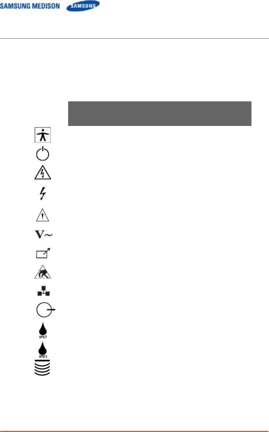
2.2.1Safety Symbols
The International Electro Technical Commission (IEC) has established a set of
symbols for medical electronic equipment, which classifies a connection or warn of potential hazards. The classifications and symbols are shown below.
Symbols |
Description |
|
|
|
Isolated patient connection (Type BF applied part). |
|
|
|
Power switch (Supplies/cuts the power for product). |
|
|
|
Indicates a caution for risk of electric shock. |
|
|
|
Indicates dangerous voltages over 1000V AC or over |
|
1500V DC. |
|
Warning, Caution |
|
|
|
AC (alternating current) voltage source |
|
|
|
Print remote output |
|
|
|
Electrostatic discharge |
|
|
|
Network port |
|
|
|
Output port ( DVI, RGB, B/W, S-VHS, SOUND ) |
|
|
|
Protection against the effects of immersion. |
|
|
|
Protection against dripping water. |
|
|
|
Probe connector |
|
|
Chapter 2. Safety 2-2
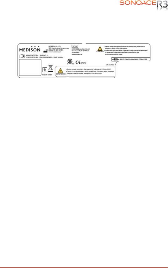
2.2.2LABEL
To protect the system, you may see ‘Warning’ or ‘Caution’ marked on the surface of the product
[Figure 2-1]Marked on the product
Chapter 2. Safety 2-3
2.3Electrical Safety
This equipment has been verified as a Class I device with Type BF applied parts.
2.3.1Prevention of Electric Shock
Additional equipment connected to medical electrical equipment must comply with the respective IEC or ISO standards (e.g. IEC 60950 for data processing equipment). Furthermore all configurations shall comply with the requirements for medical electrical systems (see IEC 60601-1-1 or clause 16 of the 3 Ed. of IEC 60601-1, respectively). Anybody connecting additional equipment to medical electrical equipment configures a medical system and is therefore responsible that the system complies with the requirements for medical electrical systems.
Attention is drawn to the fact that local laws take priority over the abovementioned requirements. If in doubt, consult your local representative or the technical service department.
˙ ˙ ˙ ˙˙˙ ˙
WARNING
zElectric shock may exist result if this system, including and all of its externally mounted recording and monitoring devices, is not properly grounded.
zDo not remove the covers on the system; hazardous voltages are present inside. Cabinet panels must be in place while the system is in use. All internal adjustments and replacements must be made by a qualified SAMSUNG MEDISON Customer Service Department.
zCheck the face, housing, and cable before use. Do not use, if the face is cracked, chipped, or torn, the housing is damaged, or if the cable is abraded.
zAlways disconnect the system from the wall outlet prior to cleaning the system.
zAll patient contact devices, such as probes and ECG leads, must be removed from the patient prior to application of a high voltage defibrillation pulse.
zThe use of flammable anesthetic gas or oxidizing gases (N20) should be avoided.
˙ ˙ ˙ ˙˙˙ ˙
CAUTION
zThe system has been designed for 100-120VAC and 200-240VAC; you should select the
inputOutlet voltage of monitor, printer and VCR. Prior to connecting an OEM power cord, verify that the voltage indicated on the power cord matches the voltage rating of the OEM device.
zAn isolation transformer protects the system from power surges. The isolation transformer continues to operate when the system is in standby.
zDo not immerse the cable in liquids. Cables are not waterproof.
zThe operator does not contact the parts (SIP/SOP) and the patient simultaneously.
Chapter 2. Safety 2-4
2.3.2ESD
Electrostatic discharge (ESD), commonly referred to as a static shock, is a naturally occurring phenomenon. ESD is most prevalent during conditions of low humidity, which can be caused by heating or air conditioning. During low humidity conditions, electrical charges naturally build up on individuals, creating static electricity. An ESD occurs when an individual with an electrical energy build-up comes in contact with conductive objects such as metal doorknobs, file cabinets, computer equipment, and even other individuals. The static shock or ESD is a discharge of the electrical energy build-up from a charged individual to a lesser or non-charged individual or object.
˙ ˙ ˙ ˙˙˙ ˙
CAUTION
zThe level of electrical energy discharged from a system user or patient to an ultrasound system can be significant enough to cause damage to the system or probes.
zAlways perform the pre-ESD preventive procedures before using connectors marked with the ESD warning label.
-Apply anti-static spray on carpets or linoleum.
-Use anti-static mats.
-Ground the product to the patient table or bed.
zIt is highly recommended that the user be given training on ESD-related warning symbols and preventive procedures.
[Figure 2-7] ESD symbol
2.3.3EMI
Although this system has been manufactured in compliance with existing EMI
(Electromagnetic Interference) requirements, use of this system in the presence of an electromagnetic field can cause momentary degradation of the ultrasound image.
If this occurs often, SAMSUNG MEDISON suggests a review of the environment in which the
system is being used, to identify possible sources of radiated emissions. These emissions could be from other electrical devices used within the same room or an adjacent room. Communication devices such as cellular phones and pagers can cause these emissions. The existence of radios, TVs, or microwave transmission equipment nearby can also cause interference.
˙ ˙ ˙ ˙˙˙ ˙
CAUTION
In cases where EMI is causing disturbances, it may be necessary to relocate this system.
Chapter 2. Safety 2-5

2.3.4EMC
The testing for EMC(Electromagnetic Compatibility) of this system has been performed according to the international standard for EMC with medical devices (IEC60601-1-2). This IEC standard was adopted in Europe as the European norm (EN60601-1-2).
2.3.4.1Guidance and manufacturer’s declaration - electromagnetic emission
This product is intended for use in the electromagnetic environment specified below. The customer or the user of this product should assure that it is used in such an environment.
|
Emission test |
|
Compliance |
|
Electromagnetic environment -guidance |
|
|
|
|
|
|
|
RF Emission |
|
Group 1 |
|
The Ultrasound System uses RF energy only |
|
(Radiation) |
|
|
for its internal function. Therefore, its RF |
|
|
|
Class B |
|
||
|
CISPR 11 |
|
|
emissions are very low and are not likely to |
|
|
|
|
|
||
|
RF Emission |
|
Group 1 |
|
cause any interference in nearby electronic |
|
(Radiation) |
|
|
equipment. |
|
|
|
Class B |
|
||
|
CISPR 11 |
|
|
The Ultrasound System is suitable for use in all |
|
|
|
|
|
||
|
Harmonic Emission |
|
ClassA |
|
establishments, including domestic |
|
IEC 61000-3-2 |
|
|
establishments and those directly connected to |
|
|
|
|
|
||
|
Flicker Emission |
|
|
|
the public low-voltage power supply network |
|
|
Complies |
|
that supplies building used for domestic |
|
|
IEC 61000-3-3 |
|
|
||
|
|
|
|
purpose. |
|
|
|
|
|
|
2.3.4.2Approved Cables, Transducers and Accessories for EMC
1)Approved Cable for Electromagnetic Compliance
Cables connected to this product may affect its emissions; Use only the cable types and lengths listed below table.
Cable |
Type |
Length |
|
|
|
VGA |
Shielded |
Normal |
Parallel |
Shielded |
Normal |
RS232C |
Shielded |
Normal |
USB |
Shielded |
Normal |
LAN(RJ45) |
Twisted pair |
Any |
S-Video |
Shielded |
Normal |
Foot Switch |
Shielded |
2.5m |
B/W Printer |
Unshielded Coaxial |
Normal |
MIC |
Unshielded |
Any |
Printer Remote |
Unshielded |
Any |
Audio R.L |
Shielded |
Normal |
VHS |
Shielded |
Normal |
ECG AUX input |
Shielded |
< 3m |
Chapter 2. Safety 2-6

2) Approved Transducer for Electromagnetic Compliance
The probe listed in ‘Chapter 8. Probes’ when used with this product, have been tested to comply with the group1 class B emission as required by International Standard CISPR 11.
3) Approved Accessories for Electromagnetic Compliance
Accessories used with this product may effect its emissions
˙ ˙ ˙ ˙˙˙ ˙
CAUTION
When connecting other customer-supplied accessories to the system, such as a remote printer or VCR, it is the user’s responsibility to ensure the electromagnetic compatibility of the system. Use only CISPR 11 or CISPR 22, CLASS B compliant devices
˙ ˙ ˙ ˙˙˙ ˙
WARNING
The use of cables, transducers, and accessories other than those specified may result inincreased emission or decreased Immunity of the Ultrasound System.
|
Immunity test |
|
|
|
IEC 60601 |
|
|
Compliance level |
|
|
Electromagnetic environment - |
|
|
|
|
|
|
Test level |
|
|
|
|
guidance |
|
|||
|
|
|
|
|
|
|
|
|
|
|
|
||
|
|
|
|
|
|
|
|
|
|
|
|
|
|
|
Electrostatic |
|
±6KV Contact |
|
±6KV |
Contact |
|
Floors should be wood, concrete |
|||||
|
|
|
|
or ceramic tile. If floors are |
|||||||||
|
|
|
|
|
|
|
|
|
|
|
|
||
|
discharge (ESD) |
|
±8KV |
air |
|
±8KV |
air |
|
covered with synthetic material, |
||||
|
IEC 61000-4-2 |
|
|
|
the relative humidity should be at |
||||||||
|
|
|
|
|
|
|
|
|
|
least 30%. |
|||
|
|
|
|
|
|
|
|
|
|
|
|
||
|
|
|
|
|
|
|
|
|
|
|
|
||
|
Electrical fast |
|
±2KV |
for power supply |
|
±2KV for power |
|
Mains power quality should be that |
|||||
|
|
|
|
|
|
of a typical commercial or hospital |
|||||||
|
transient/burst |
|
lines |
|
|
|
supply lines |
|
|||||
|
|
|
|
|
|
environment. |
|||||||
|
|
|
|
±1KV for input/output |
|
±1KV for input/ |
|
||||||
|
|
|
|
|
|
|
|
||||||
|
IEC 61000-4-4 |
|
lines |
|
|
|
output lines |
|
|
|
|||
|
|
|
|
|
|
|
|
|
|
|
|
||
|
|
|
|
|
|
|
|
|
|
|
|
|
|
|
Surge |
|
±1KV differential mode |
|
±1KV differential mode |
|
Mains power quality should be that |
||||||
|
IEC 61000-4-5 |
|
|
|
|||||||||
|
|
±2KV common mode |
|
±2KV common mode |
|
of a typical commercial or hospital |
|||||||
|
|
|
|
|
|
environment. |
|||||||
|
|
|
|
|
|
|
|
|
|
|
|
||
|
|
|
|
|
|
|
|
||||||
|
Voltage dips, short |
|
<5% Uт |
|
<5% Uт |
|
Mains power quality should be that |
||||||
|
interruptions and |
|
(>95% dip in Uт) |
|
(>95% dip in Uт) |
|
of a typical commercial or hospital |
||||||
|
voltage variations |
|
for 0.5cycle |
|
for 0.5cycle |
|
environment. If the user of this |
||||||
|
on power supply |
|
|
|
|
|
|
|
|
|
product requires continued |
||
|
input lines |
|
40% Uт |
|
40% Uт |
|
|
|
operation during power mains |
||||
|
|
|
|
(60% dip in Uт ) |
|
(60% dip in Uт ) |
|
interruptions, it is recommended |
|||||
|
IEC 61000-4-11 |
|
for 5 cycle |
|
for 5 cycle |
|
that this product be powered from |
||||||
|
|
|
|
|
|
|
|
|
|
|
|
an uninterruptible power supply or |
|
|
|
|
|
70% Uт |
|
70% Uт |
|
|
|
a battery. |
|||
|
|
|
|
(30% dip in Uт) |
|
(30% dip in Uт) |
|
|
|
||||
|
|
|
|
for 25 cycle |
|
for 25 cycle |
|
|
|
||||
|
|
|
|
<5% Uт |
|
<5% Uт |
|
|
|
||||
|
|
|
|
(<95% dip in Uт ) |
|
(<95% dip in Uт ) |
|
|
|
||||
|
|
|
|
for 5 s |
|
|
|
for 5 s |
|
|
|
|
|
Chapter 2. Safety 2-7
Power frequency |
|
|
|
|
|
Power frequency magnetic fields |
(50/60Hz) |
|
|
|
|
|
should be at levels characteristic |
magnetic field |
|
3 A/m |
|
3 A/m |
|
of a typical location in a typical |
|
|
|
|
|
|
commercial or hospital |
IEC 61000-4-8 |
|
|
|
|
|
environment. |
NOTE Uт is the a.c. mains voltage prior to application of the test level. |
|
|
||||
|
|
|
|
|||
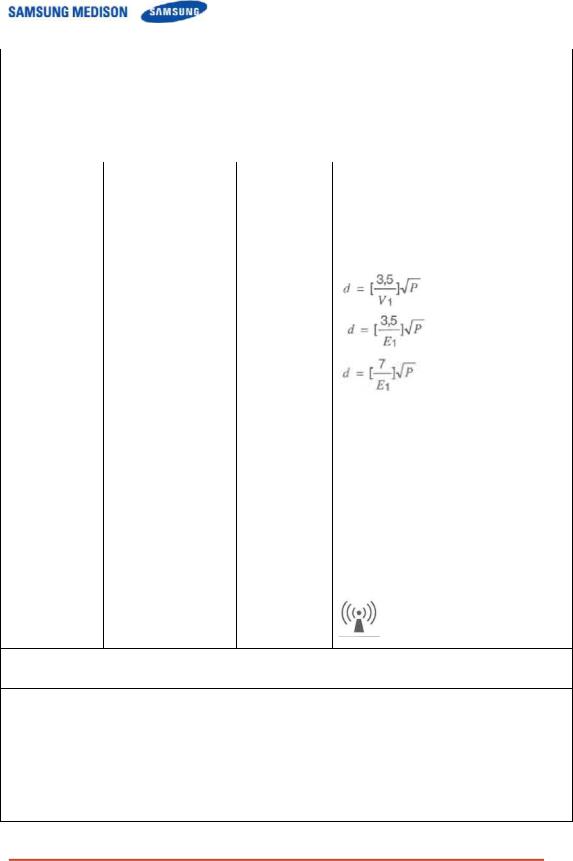
Conducted RF |
3 Vrms |
0.01V |
Portable and mobile RF communications |
|||
IEC 61000-4-6 |
150 kHz to 80MHz |
|
|
equipment should be used no closer to any part |
||
|
|
of the Ultrasound System, including cables, |
||||
|
|
|
|
|
||
|
|
|
|
|
than the recommended separation distance |
|
|
|
|
|
|
calculated from the equation applicable to the |
|
|
|
|
|
|
frequency of the transmitter. |
|
|
|
|
|
|
Recommended separation distance |
|
|
|
|
80MHz to 800MHZ |
|
|
|
800MHz to 2.5GHz |
Radiated RF |
3 V/m |
3 V/m |
Where P is the maximum output power rating of |
IEC 61000-4-3 |
80 MHz to 2.5GHz |
|
the transmitter in watts (W) according to the |
|
transmitter manufacturer and d is the |
||
|
|
|
|
|
|
|
recommended separation distance in meters |
|
|
|
(m). |
|
|
|
Field strengths from fixed RF transmitters, as |
|
|
|
deter-mined by an electromagnetic site survey, a |
|
|
|
should be less than the compliance level in |
|
|
|
each frequency range. b |
|
|
|
Interference may occur in the vicinity of |
|
|
|
equipment marked with the following symbol : |
NOTE 1) At 80MHz and 800MHz, the higher frequency range applies.
NOTE 2) These guidelines may not apply in all situations. Electromagnetic propagation is affected by absorption and reflection from structures, objects and people.
a Field strengths from fixed transmitters, such as base stations for radio (cellular/cordless) telephones and land mobile radios, amateur radio, AM and FM radio broadcast and TV broadcast cannot be predicted theoretically with accuracy. To assess the electromagnetic environment due to fixed RF transmitters, an electromagnetic site survey should be considered. If the measured field strength in the location in which the Ultrasound System is used exceeds the applicable RF compliance level above, the Ultrasound System should be observed to verify normal operation. If abnormal performance is observed, additional measures may be necessary, such as re-orienting or relocating the Ultrasound System or using a shielded location with a higher RF shielding effectiveness and filter attenuation.
b Over the frequency range 150kHz to 80MHz, field strengths should be less than [V1] V/m.
Chapter 2. Safety 2-8
 Loading...