


NETWORK CAMERA
User Manual SNF-8010/SNF-8010VM

Network Camera
User Manual
Copyright
©2014 Samsung Techwin Co., Ltd. All rights reserved.
Trademark
 is the registered logo of Samsung Techwin Co., Ltd. The name of this product is the registered trademark of Samsung Techwin Co., Ltd.
Other trademarks mentioned in this manual are the registered trademark of their respective company.
Restriction
Samsung Techwin Co., Ltd shall reserve the copyright of this document. Under no circumstances, this document shall be reproduced, distributed or changed, partially or wholly, without formal authorization of Samsung Techwin.
Disclaimer
Samsung Techwin makes the best to verify the integrity and correctness of the contents in this document, but no formal guarantee shall be provided. Use of this document and the subsequent results shall be entirely on the user’s own responsibility. Samsung Techwin reserves the right to change the contents of this document without prior notice.
Design and specifications are subject to change without prior notice.
The initial administrator ID is “admin” and the password should be set when logging in for the first time. Please change your password every three months to safely protect personal information and to prevent the damage of the information theft.
Please, take note that it’s a user’s responsibility for the security and any other problems caused by mismanaging a password.

overview
Important Safety Instructions
1. |
Read these instructions. |
|
|
2. |
Keep these instructions. |
|
|
3. |
Heed all warnings. |
● |
|
4. |
Follow all instructions. |
overview |
|
|
|
||
5. |
Do not use this apparatus near water. |
|
|
6. |
Clean only with dry cloth. |
|
|
7. |
Do not block any ventilation openings, Install in accordance with the manufacturer’s |
|
|
8. |
instructions. |
|
|
Do not install near any heat sources such as radiators, heat registers, stoves, or other |
|
|
|
9. |
apparatus (including amplifiers) that produce heat. |
|
|
Do not defeat the safety purpose of the polarized or grounding-type plug. A polarized |
|
|
|
|
plug has two blades with one wider than the other. A grounding type plug has two |
|
|
|
blades and a third grounding prong. The wide blade or the third prong are provided for |
|
|
|
your safety. If the provided plug does not fit into your outlet, consult an electrician for |
|
|
10. |
replacement of the obsolete outlet. |
|
|
Protect the power cord from being walked on or pinched particularly at plugs, |
|
|
|
11. |
convenience receptacles, and the point where they exit from the apparatus. |
|
|
Only use attachments/ accessories specified by the manufacturer. |
|
|
|
12. |
Use only with the cart, stand, tripod, bracket, or table specified by |
|
|
|
the manufacturer, or sold with the apparatus. When a cart is used, |
|
|
|
use caution when moving the cart/apparatus combination to avoid |
|
|
13. |
injury from tip-over. |
|
|
Unplug this apparatus during lighting storms or when unused for |
|
|
|
14. |
long periods of time. |
|
|
Refer all servicing to qualified service personnel. Servicing is required when the |
|
|
|
|
apparatus has been damaged in any way, such as power-supply cord or plug is |
|
|
|
damaged, liquid has been spilled or objects have fallen into the apparatus, the apparatus |
|
|
|
has been exposed to rain or moisture, does not operate normally, or has been dropped. |
|
|
English _3

overview
WARNING
TO REDUCE THE RISK OF FIRE OR ELECTRIC SHOCK, DO NOT EXPOSE THIS PRODUCT TO RAIN OR MOISTURE. DO NOT INSERT ANY METALLIC OBJECT THROUGH THE VENTILATION GRILLS OR OTHER OPENNINGS ON THE EQUIPMENT.
Apparatus shall not be exposed to dripping or splashing and that no objects filled with liquids, such as vases, shall be placed on the apparatus.
To prevent injury, this apparatus must be securely attached to the Wall/ceiling in accordance with the installation instructions.
CAUTION
CAUTION
RISK OF ELECTRIC SHOCK.
DO NOT OPEN
CAUTION : TO REDUCE THE RISK OF ELECTRIC SHOCK.
DO NOT REMOVE COVER (OR BACK).
NO USER SERVICEABLE PARTS INSIDE.
REFER SERVICING TO QUALIFIED SERVICE PERSONNEL.
EXPLANATION OF GRAPHICAL SYMBOLS
The lightning flash with arrowhead symbol, within an equilateral triangle, is intended to alert the user to the presence of “dangerous voltage” within the product’s enclosure that may be of sufficient magnitude to constitute a risk of electric shock to persons.
The exclamation point within an equilateral triangle is intended to alert the user to the presence of important operating
and maintenance (servicing) instructions in the literature accompanying the product.
4_ overview

Class  construction
An apparatus with CLASS construction shall be connected to a MAINS socket outlet with a protective earthing connection.
Battery
Batteries(battery pack or batteries installed) shall not be exposed to excessive heat such as sunshine, fire or the like.
Disconnection Device
Disconnect the main plug from the apparatus, if it’s defected. And please call a repair man in your location.
When used outside of the U.S., it may be used HAR code with fittings of an approved agency is employed.
CAUTION
Risk of explosion if battery is replaced by an incorrect type. Dispose of used batteries according to the instructions.
These servicing instructions are for use by qualified service personnel only. To reduce the risk of electric shock do not perform any servicing other than that contained in the operating instructions unless you are qualified to do so.
Please use the input power with just one camera and other devices must not be connected.
The ITE is to be connected only to PoE networks without routing to the outside plant.
overview ●
English _5

overview
Please read the following recommended safety precautions carefully.
yyDo not place this apparatus on an uneven surface.
yyDo not install on a surface where it is exposed to direct sunlight, near heating equipment or heavy cold area.
yyDo not place this apparatus near conductive material. yyDo not attempt to service this apparatus yourself. yyDo not place a glass of water on the product.
yyDo not install near any magnetic sources. yyDo not block any ventilation openings. yyDo not place heavy items on the product.
User’s Manual is a guidance book for how to use the products. The meaning of the symbols are shown below.
yyReference : In case of providing information for helping of product’s usages
yyNotice : If there’s any possibility to occur any damages for the goods and human caused by not following the instruction
Please read this manual for the safety before using of goods and keep it in the safe place.
6_ overview

CONTENTS
overview |
9 |
Product Features |
3 |
3 |
Important Safety Instructions |
10 |
Recommended PC Specifications |
|
10 |
Recommended Micro SD/ |
|
|
SDHC/SDXC Memory Card |
|
|
11 |
Specifications |
|
NAS recommended specs |
|
|
11 |
What’s Included |
|
13 |
At a Glance |
installation & connection
16
network connection and setup
28
16 Installation
19Inserting/Removing a Micro SD Memory Card
20Memory Card Information (Not Included)
21Connecting with other Device
28 Connecting the Camera Directly to Local Area Networking
29 Connecting the Camera Directly to a DHCP Based DSL/Cable Modem
30 Connecting the Camera Directly to a PPPoE Modem
31 Connecting the Camera to a Broadband Router with the PPPoE/Cable Modem
32 Buttons used in IP Installer
33 Static IP Setup
37 Dynamic IP Setup
38 Port Range Forward (Port Mapping) Setup
40 Connecting to the Camera from a Shared Local PC
40 Connecting to the Camera from a Remote PC via the Internet
overview ●
English _7

overview
web viewer
41
setup screen
57
appendix
113
41 Connecting to the Camera
43 Password setting
43Login
44Installing STW WebViewer Plugin
46Using the Live Screen
50Playing the recorded video
57 |
Setup |
57 |
Basic Setup |
70 |
Video & Audio setup |
79 |
Network Setup |
88 |
Event Setup |
93 |
NAS (Network Attached Storage) |
107 |
guide |
System Setup |
|
112 |
Viewing profile information |
113 |
Specification |
120 |
Product Overview |
122 |
Troubleshooting |
124 |
Open source license notification |
on the product
8_ overview

Product Features
•• Fisheye lens
This lens has 360˚ vision and it can record video panoramically.
If you use Smart Viewer on your PC, you can view corrected video in real time.
•• Dustproof/Waterproof (IP66) (SNF-8010VM)
The dustproof and waterproof design makes you feel at ease when installing the product
outdoors or exposing it to rain.
•• HD Video Quality
•• Multi-Streaming
This network camera can display videos in different resolutions and qualities simultaneously using different CODECs.
•• Web Browser-based Monitoring
Using the Internet web browser to display the image in a local network environment.
•• Alarm
When an event occurs, the captured video of the event is sent to the e-mail and FTP server registered by the user or is saved in the Micro SD memory card or NAS.
•• Tampering Detection
If the monitoring is interrupted in any way, the camera will trigger the event alarm.
•• Video Motion Detection
Detects a motion from the video before triggering an event.
•• Audio Detection
Detects sound louder than a certain level specified by user.
•• Auto Detection of Disconnected Network
Detects network disconnection before triggering an event.
•• ONVIF Compliance
This product supports ONVIF Profile-S.
For more information, refer to www.onvif.org.
JJ`` This piece of equipment is a high resolution video transmission tool that supports a resolution of 2 mega pixels or higher. When you transmit high resolution video with a resolution higher than what is supported by the RFC2435 (RTP payload format for JPEG), the existing low resolution spec, it uses the Onvif JPEG extension header method for transmission of high resolution video.
Thus, when you transmit high resolution video to external equipment or S/W using Onvif, you need to check whether your client equipment or S/W supports the most up-to-date spec, Onvif JPEG extension header method.
overview ●
English _9

overview
Recommended PC Specifications
•• CPU : Chips sporting Intel Core i5 or higher
`` Web Plug-in is optimized to SSE 4.1 Instruction Set.
•• Resolution : 2048X1536 pixels or higher (32 bit color)
•• RAM : 2GB or higher
•• Supported OS : Windows XP / VISTA / 7 / 8, MAC OS X 10.7
•• Supported Browser : Microsoft Internet Explorer (Ver. 8~11)
Mozilla Firefox (Ver. 9~19), Google Chrome (Ver. 15~25),
Apple Safari (Ver. 6.0.2(Mac OS X 10.8, 10.7 only), 5.1.7) Mac OS X only
`` Windows 8 is supported only in the Desktop mode.
`` Neither a beta test version unlike the version released in the company website nor the developer version will be supported.
`` For IPv6 connection, Window 7 or higher is recommended. `` For Mac OS X, only the Safari browser is supported.
•• Video Memory : 256MB or higher
JJ``
``
If the driver of the video graphic adapter is not installed properly or is not the latest version, the video may not be played properly.
For a multi-monitoring system involving at least 2 monitors, the playback performance can be deteriorated depending on the system.
Recommended Micro SD/SDHC/SDXC Memory Card
Specifications
•• 4GB ~ 64GB
•• For your camera, we recommend you use a memory card from the following manufacturers:
Micro SD/SDHC/SDXC Memory Card : Sandisk, Transcend
•• It is recommended a memory card of specification Class 6 or higher is used.
10_ overview
NAS recommended specs
•• Recommended capacity : 200GB or higher is recommended.
•• Simultaneous access : One unit of NAS can accept a maximum of sixteen camera accesses.
•• For this camera, you are recommended to use a NAS with the following manufacturer’s specs.
|
|
|
|
Recommended products |
Available sizes |
|
Netgear NAS |
A maximum of 16 cameras can access simultaneously. |
|
Synology NAS |
A maximum of 16 cameras can access simultaneously. |
JJ`` |
When you use Netgear’s NAS equipment, do not allocate the capacity for use. |
|
`` |
If you use NAS equipment for purposes other than video saving, the number of accessible |
|
|
cameras may be reduced. |
|
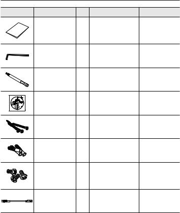
What’s Included
Please check if your camera and accessories are all included in the product package.
Appearance |
Item Name |
Quantity |
Description |
Model Name |
|
|
1 |
|
|
|
Camera |
|
|
SNF-8010 or |
|
|
|
SNF-8010VM |
|
|
|
|
|
|
|
|
1 |
|
|
|
Instruction book, |
1 |
|
SNF-8010/ |
|
Installer S/W CD |
|
SNF-8010VM |
|
|
|
|
||
|
Quick Guide |
1 |
|
SNF-8010/ |
|
(Optional) |
|
SNF-8010VM |
|
|
|
|
overview ●
English _11
overview
Appearance |
Item Name |
Quantity |
Description |
Model Name |
|
Warranty card |
1 |
|
SNF-8010/ |
|
(Optional) |
|
SNF-8010VM |
|
|
|
|
||
|
L Wrench |
1 |
To remove/fix the cover top |
SNF-8010/ |
|
SNF-8010VM |
|||
|
|
|
|
|
|
|
|
Used to disassemble or |
SNF-8010/ |
|
Drill bit |
1 |
assemble the top cover, or |
|
|
SNF-8010VM |
|||
|
|
|
install the camera. |
|
|
|
|
|
|
|
Template |
1 |
Product installation guide |
SNF-8010/ |
|
SNF-8010VM |
|||
|
|
|
|
|
|
Tapping Screw |
3 |
Used for installation on the |
SNF-8010/ |
|
wall or ceiling |
SNF-8010VM |
||
|
|
|
||
|
|
|
For fixing a screw, |
SNF-8010/ |
|
Plastic Anchor |
3 |
Inserted in a hole |
|
|
SNF-8010VM |
|||
|
|
|
(reinforced anchoring force) |
|
|
|
|
|
|
|
|
|
Used for assembling the dome |
SNF-8010/ |
|
Machine Screws |
3 |
case when installing the product |
|
|
on the pipe, wall mount, etc. or |
SNF-8010VM |
||
|
|
|
blocking a hole. |
|
|
M12-RJ45 conversion |
|
Using it to connect the M12 |
|
|
1 |
connector of your camera to |
SNF-8010VM |
|
|
cable |
|||
|
|
general network equipment |
|
|
|
|
|
|
12_ overview
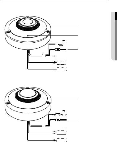
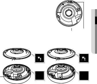
At a Glance
Appearance
a b


 c
c
d


 e
e

 f
f


 g
g
<SNF-8010>
a


 c
c
d


 h
h

 f
f


 g
g
<SNF-8010VM>
overview ●
English _13

overview
Item |
|
Description |
|
a Cover top |
SNF-8010 |
Case cover used to protect the main unit. |
|
|
|
||
SNF-8010VM |
Case cover used to protect the lens and the main unit. |
||
|
|||
|
|
|
|
b Microphone hole |
A microphone is embedded. |
||
` It is applicable only to the SNF-8010 model. |
|||
|
` |
|
|
c Power Port |
Used to plug the power cable. |
||
|
|
|
|
|
ALARM IN |
Used to connect the alarm input sensor. |
|
d Alarm I/O Port |
ALARM OUT |
Used to connect the alarm output signal. |
|
|
GND |
Common port for alarm output signal. |
|
e Network Port |
Used to connect the PoE or Ethernet cable for network connection. |
||
f Audio Out Jack |
Used to connect to speakers. (green) |
||
g Audio In Jack |
Used to connect to a microphone. (pink) |
||
|
|
|
|
h M12 Female |
Connect to the M12 Male connector cable for power supply and network |
||
connector cable |
connections. |
|
|
14_ overview
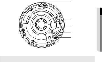
Inside
|
a |
MIC |
b |
|
c |
RESET |
d |
|
e |
overview ●
Item |
Description |
a Camera fixing hole |
Hole used for securing the camera onto a ceiling. |
|
|
b MIC |
The MIC is built into the camera. |
` |
|
` It is applicable only to the SNF-8010 model. |
|
c Fisheye lens |
This lens has 360˚ vision and it can record video panoramically. |
|
|
Micro SD Memory |
Compartment for the Micro SD memory card. |
d Card Compartment |
|
|
The button restores all camera settings to the factory default. |
|
Press and hold for about 5 seconds to reboot the system. |
e Reset Button |
J If you reset the camera, the network settings will be adjusted so that |
DHCP can be enabled. If there is no DHCP server in the network, you |
|
|
must run the IP Installer program to change the basic network settings |
|
such as IP address, Subnet mask, Gateway, etc., before you can |
|
connect to the network. |
English _15
installation & connection
Installation
JJ`` This camera(SNF-8010VM) is waterproof and in compliance with the IP66 spec, but the jack connected to the external cable is not. You are recommended to install this product below the edge of eaves to prevent the cable from being externally exposed.
Precautions before installation
Ensure you read out the following instructions before installing the camera:
•• Select an installation site that can hold at least 5 times the camera’s weight.
•• Stuck-in or peeled-off cables can cause damage to the product or a fire.
•• For safety purposes, keep anyone else away from the installation site. And put aside personal belongings from the site, just in case.
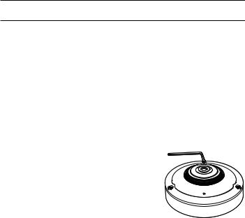
Disassembling
1. Using the L-shaped wrench or drill bit provided
with the product, unwind the three nuts in a clockwise direction to remove the top cover.
`` Note that it is not necessary to loosen the screws completely.
16_ installation & connection
Installing the camera on the ceiling or a wall
1.Select a location where you want to install the camera.
2.Insert the provided screw into the camera hole and turn it clockwise.
MIC ationll 


 ta●s&in


 connection
Fixing Hole
3.Using the L shaped wrench or drill bit, fasten the top cover in place in a clockwise direction.
MIC
MIC
|
<SNF-8010> |
<SNF-8010VM> |
JJ`` |
To fix the cover, you should match the triangular arrows to assemble correctly. |
|
`` |
If the cover is not fixed tightly, you may encounter a problem with waterproofing. (IP66) |
|
|
(SNF-8010VM) |
|
English _17
installation & connection
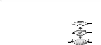
Outdoor installation (SNF-8010VM)
When you install the camera outdoors, it should be waterproofed with waterproof butyl |
|||||||||||||
rubber tape (which can be purchased in stores) so that water does not leak from the gap of |
|||||||||||||
the cable connected in the outdoor area. |
|
|
|
|
|
|
|
|
|
|
|
|
|
1. Connect the power, audio I/O and LAN |
|
|
|
|
|
|
|
|
|
|
|
|
|
|
Camera |
|
|
|
|
|
|
|
|
|
|
System |
|
cables. |
|
|
|
|
|
|
|
|
|
|
|
|
|
2. Wrap the black cable jacket (Area A) and the |
|
|
|
|
|
|
|
|
|
|
|
|
|
cable connection area with waterproof (butyl |
|
|
|
|
|
|
|
|
|
|
|
|
|
Camera |
|
|
|
|
|
|
|
|
|
|
System |
||
rubber) tape so that more than half of the |
|
|
|
|
|
|
|
|
|
|
|
|
|
|
|
|
|
|
|
|
|
|
|
|
|
||
butyl rubber tape is overlapped. |
|
A |
|
|
|
|
|
|
|
|
A |
||
|
|
|
|
|
|
|
|
|
|
|
|
|
|
JJ`` If the cable jacket is not waterproofed properly, |
Camera |
|
|
|
|
|
|
|
|
|
|
System |
|
|
|
|
|
|
|
|
|
|
|
|
|
||
|
|
|
|
|
|
|
|
|
|
|
|
||
then it can directly cause leakage. Make sure to |
|
|
|
|
|
|
|
|
|
|
|
|
|
protect the cable with a dense layer of taping. |
|
|
|
|
|
|
|
|
|
|
|
|
|
`` Waterproof butyl tape is made of butyl rubber that can be stretched to twice its normal length. |
|||||||||||||
18_ installation & connection

Inserting/Removing a Micro SD Memory Card
JJ`` Disconnect the power cable from the camera before inserting the Micro SD memory card.
`` Do not insert the Micro SD memory card while it’s upside down by force. Otherwise, it may damage the Micro SD memory card.
Inserting a Micro SD Memory Card
Push the Micro SD memory card in the direction of the arrow shown in the diagram.
Removing a Micro SD Memory Card
Gently press down on the exposed end of the memory card as shown in the diagram to eject the memory card from the slot.
connectionin&sta●ationll
English _19

installation & connection
JJ``
``
``
Pressing too hard on the Micro SD memory card can cause the card to shoot out uncontrollably from the slot when released.
Before removing your Micro SD memory card, turn off the camera or go to <Storage>, turn the device off, and press the [Apply ( )] button. (Page 89)
If you turn off the camera or remove the Micro SD memory card that contains data from the product, the data may be lost or damaged.
Memory Card Information (Not Included)
What is a memory card?
The memory card is an external data storage device that has been developed to offer an entirely new way to record and share video, audio, and text data using digital devices.
Selecting a memory card that’s suitable for you
Your camera supports Micro SD/SDHC/SDXC memory cards.
You may, however, experience compatibility issues depending on the model and make of the memory card.
For your camera, we recommend you use a memory card from the following manufacturers:
Micro SD/SDHC/SDXC Memory Card : Sandisk, Transcend
Memory cards of 4GB ~ 64GB is recommended for using with this camera.
Playback performance can be affected depending on the speed of memory card, so use the high-speed memory card.
It is recommended a memory card of specification Class 6 or higher is used.
Memory Card Components
Contacts 


Micro SD/SDHC/SDXC
20_ installation & connection
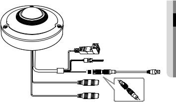
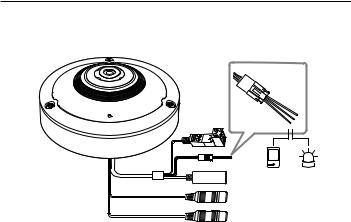
Connecting with other Device
Power
RJ-45 |
<SNF-8010>
Power
M12
<SNF-8010VM>
connectionin&sta●ationll
English _21

installation & connection
Ethernet Connection
Connect the Ethernet cable to the local network or to the Internet.
Power Supply
Use the screwdriver to connect each line (+, –) of the power cable to the corresponding power port of the camera.
JJ`` IfPoE.both PoE and DC12V are applied simultaneously, the product will be supplied with power from
-- You can also use a router featuring PoE to supply power to the camera.
-- Use PoE that is compliant with the IEEE802.3af protocols.
`` Be careful not to reverse the polarity when you connect the power cable.
`` If you want to connect an external device, you must turn off the external device before proceeding.
Connecting a connector cable (SNF-8010VM)
Connect the M12 male connector into the hole of the M12 Female connector of the camera.
MM`` This camera uses Female, D-coded types. `` PoE (Power over Ethernet) is supported.
`` You are recommended to use a shielded network connector.
JJ`` |
Connect this camera to a shielded network cable (STP). |
RX- |
TX+ |
`` |
Please, use 4 poles, Male, D-coded type external cables that |
|
|
`` |
meet the M12 specification. |
|
|
Check whether the PoE device is properly connected to the |
|
|
|
|
ground. |
|
|
|
|
TX- |
RX+ |
22_ installation & connection
Making a connection using the M12-RJ45 conversion cable provided (SNF-8010VM)
Connect the M12 male connector for the conversion cable to the groove of the M12 Female connector for your camera.
Powering and networking (SNF-8010VM)
Connect a camera to a PoE equipment or connect the provided M12-RJ45 connector for the conversion cable of your camera to a PoE equipment.
JJ`` A connection method may vary depending on the installation environment of a user. `` Connect to a PoE (Power over Ethernet) enabled router’s PoE connector.
`` Use PoE (Power over Ethernet) that is compliant with the IEEE802.3af protocols.
You can only use a Mode A PoE device that supplies power through data pin pair 1, 2, 3, 6.
`` Even if you use the M12-RJ45 conversion cable provided, you can only use a mode A type PoE equipment that supplies power to data pair pins 1, 2, 3, 6.
connectionin&sta●ationll
English _23

installation & connection
Power Cable Specification for Each Model
In case of DC 12V Input: |
|
|
|
|
|
|
|
Wire Type (AWG) |
|
#22 |
#20 |
|
#18 |
|
|
Cable Length (Max.) |
|
24m |
38m |
|
60m |
||
Network Cable Specification |
|
|
|
|
|
|
|
Item |
|
Contents |
|
Remark |
|
||
Connector |
|
RJ45 |
|
|
|
|
|
Ethernet |
|
10/100Base-T |
|
10/100 Mbps |
|
||
Cable |
|
UTP Category 5e |
|
|
|
|
|
Max Distance |
|
100M |
|
|
|
|
|
PoE Support |
|
IEEE 802.3af |
|
|
|
|
|
24_ installation & connection
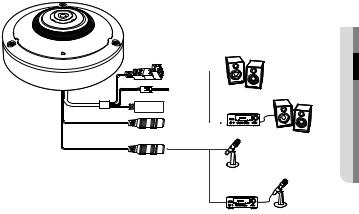
Connecting to Audio Input/Output
|
&sta●ationll |
Speaker |
connectionin |
|
|
Amp |
Speaker |
|
|
Microphone |
|
Amp |
Microphone |
1.Connect the AUDIO IN port of the camera with the microphone or LINE OUT port of the amplifier that the microphone is connected to.
MM`` As a microphone is built in, you can use the built-in microphone instead of an external one. (It is applicable only to the SNF-8010 model.)
2.Connect the AUDIO OUT port of the camera with the speaker or LINE IN port of the amplifier that the speaker is connected to.
3.Check the specifications for audio input.
•• Audio Codec
-- Audio In : G.711 PCM (Bit Rate: 64kbps / Sampling Frequency: 8kHz), G.726 ADPCM (Bit Rate: 16Kbps, 24Kbps, 32Kbps, 40Kbps / Sampling Frequency: 8kHz)
-- Audio Out : G.711 PCM (Bit Rate: 64kbps / Sampling Frequency: 8kHz)
•• Full duplex Audio
•• Audio in : Mono signal line input (Max.2.4 Vpp)
•• Audio out : Mono signal line output (Max.2.4 Vpp)
•• Line out impedance : 600Ω
English _25
installation & connection
Connecting to the I/O port box
Connect the Alarm I/O cable to the corresponding port of the port box.
Sensor Alarm
(Warning lamp)
•• ALARM-IN : Used to connect the alarm input sensor.
•• ALARM-OUT : Used to connect the alarm output signal.
•• GND : Common terminal to connect alarm signals.
JJ`` If devices (e.g., flashing light and siren) that exceed the voltage and current specifications are connected by using the open collector method, it may cause malfunction.
Refer to the “Alarm Out Wiring Diagram” when connecting devices that exceed the voltage and current specifications. (page 27)
26_ installation & connection
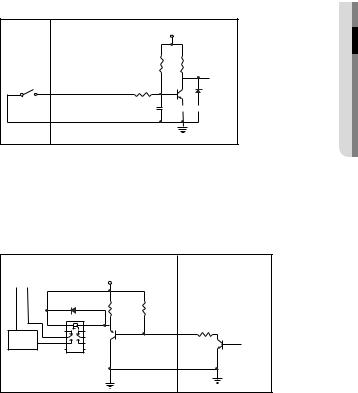
To connect the external sensor
Connect one strand of each signal line (2-strand) of the sensors to the [ALARM IN] port, and connect the other strand to the [GND] port.
Alarm In Wiring Diagram
External |
Inside of the camera |
VCC_3.3V |
|
connection |
|
|
|
|
|
RESISTOR |
RESISTOR |
Sensor |
ALARM IN (5mA SINK) |
RESISTOR |
DIODE |
|
|||
|
|
MLCC |
TRANSISTOR |
|
GND |
|
GND |
|
|
|
|
To connect the alarm out
If devices (e.g., flashing light and siren) that exceed the voltage and current specifications are connected by using the open collector method, it may cause malfunction.
Refer to the alarm out connection diagram below when connecting devices that exceed the voltage and current specifications.
Alarm Out Wiring Diagram
Warning lamp / |
External connection |
|
Inside of the camera |
|
DC 5V or 3.3V |
|
|
||
Siren power |
|
|
|
|
(-) |
(+) |
|
|
|
|
|
DIODE |
10K ohm |
|
|
|
RESISTOR |
|
|
|
|
|
ALARM OUT (12VDC 20mA MAX) |
|
|
|
TRANSISTOR |
|
RESISTOR |
Warning lamp / |
RELAY |
|
TRANSISTOR |
|
|
Siren |
|
|
|
|
|
|
GND |
GND |
|
|
GND |
|
|
|
|
|
|
|
connectionin&sta●ationll
English _27
network connection and setup
You can set up the network settings according to your network configurations.
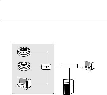
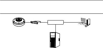
Connecting the Camera Directly to Local Area Networking
Connecting to the camera from a local PC in the LAN
1.Launch an Internet browser on the local PC.
2.Enter the IP address of the camera in the address bar of the browser.
Camera |
Camera |
INTERNET 
External Remote PC
Local PC |
DDNS Server |
(Data Center, KOREA) |
<Local Network>
MM`` A remote PC in an external Internet out of the LAN network may not be able to connect to the camera installed in the intranet if the port-forwarding is not properly set or a firewall is set. In this case, to resolve the problem, contact your network administrator.
`` In the IP installer, you can use the initial password, “4321” to set IP Address, Subnet Mask, Gateway, HTTP Port, VNP Port, IP type. After changing the network interface, for better security, access the web viewer and change the password.
`` By factory default, the IP address will be assigned from the DHCP server automatically. If there is no DHCP server available, the IP address will be set to 192.168.1.100.
To change the IP address, use the IP Installer.
For further details on IP Installer use, refer to “Static IP Setup”. (Page 33)
28_ network connection and setup
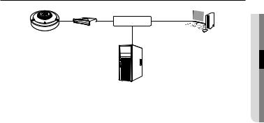
Connecting the Camera Directly to a DHCP Based DSL/Cable Modem
|
INTERNET |
Camera |
DSL/Cable Modem |
External Remote PC |
DDNS Server
(Data Center, KOREA)
1.Connect the user PC directly with the network camera.
2.Run the IP Installer and change the IP address of the camera so that you can use the web browser on your desktop to connect to the Internet.
3.Use the Internet browser to connect to the web viewer.
4.Move to [Setup] page.
5.Move to [Network] – [DDNS] and configure the DDNS settings.
6.Move to [Basic] – [IP & Port], and set the network type to [DHCP].
7.Connect the camera, which was removed from your PC, directly to the modem.
8.Restart the camera.
MM`` For registering the DDNS settings, refer to “Registering with DDNS”. (page 80)
`` For configuring the DDNS settings, refer to “DDNS”. (page 79) `` Refer to “IP & Port” for how to setup IP. (page 65)
etupd s
networan connection● k
English _29
network connection and setup
Connecting the Camera Directly to a PPPoE Modem
|
INTERNET |
Camera |
PPPoE Modem |
External Remote PC |
DDNS Server
(Data Center, KOREA)
1.Connect the user PC directly with the network camera.
2.Run the IP Installer and change the IP address of the camera so that you can use the web browser on your desktop to connect to the Internet.
3.Use the Internet browser to connect to the web viewer.
4.Move to [Setup] page.
5.Move to [Network] – [DDNS] and configure the DDNS settings.
6.Move to [Basic] – [IP & Port] Setup Page, set the network type to [PPPoE], and enter the network service’s ID and password.
7.Connect the camera, which was removed from your PC, directly to the modem.
8.Restart the camera.
MM`` For registering the DDNS settings, refer to “Registering with DDNS”. (page 80)
`` For configuring the DDNS settings, refer to “DDNS”. (page 79) `` Refer to “IP & Port” for how to setup IP. (page 65)
30_ network connection and setup
 Loading...