


NETWORK CAMERA
User Manual
SNB-6011

Network Camera
User Manual
Copyright
©2015 Samsung Techwin Co., Ltd. All rights reserved.
Trademark


 is the registered logo of Samsung Techwin Co., Ltd. The name of this product is the registered trademark of Samsung Techwin Co., Ltd.
Other trademarks mentioned in this manual are the registered trademark of their respective company.
Restriction
Samsung Techwin Co., Ltd shall reserve the copyright of this document. Under no circumstances, this document shall be reproduced, distributed or changed, partially or wholly, without formal authorization of Samsung Techwin.
Disclaimer
Samsung Techwin makes the best to verify the integrity and correctness of the contents in this document, but no formal guarantee shall be provided. Use of this document and the subsequent results shall be entirely on the user’s own responsibility. Samsung Techwin reserves the right to change the contents of this document without prior notice.
Design and specifications are subject to change without prior notice.
The initial administrator ID is “admin” and the password should be set when logging in for the first time.
Please change your password every three months to safely protect personal information and to prevent the damage of the information theft.
Please, take note that it’s a user’s responsibility for the security and any other problems caused by mismanaging a password.

overview
IMPORTANT SAFETY INSTRUCTIONS
1. |
Read these instructions. |
|
|
2. |
Keep these instructions. |
|
|
3. |
Heed all warnings. |
● |
|
OVERVIEW |
|
||
4. |
Follow all instructions. |
|
|
|
|
||
5. |
Do not use this apparatus near water. |
|
|
6. |
Clean only with dry cloth. |
|
|
7. |
Do not block any ventilation openings, Install in accordance with the manufacturer’s |
|
|
8. |
instructions. |
|
|
Do not install near any heat sources such as radiators, heat registers, stoves, or other |
|
|
|
9. |
apparatus (including amplifiers) that produce heat. |
|
|
Do not defeat the safety purpose of the polarized or grounding-type plug. A polarized |
|
|
|
|
plug has two blades with one wider than the other. A grounding type plug has two |
|
|
|
blades and a third grounding prong. The wide blade or the third prong are provided for |
|
|
|
your safety. If the provided plug does not fit into your outlet, consult an electrician for |
|
|
|
|
|
|
10. |
replacement of the obsolete outlet. |
|
|
Protect the power cord from being walked on or pinched particularly at plugs, |
|
|
|
11. |
convenience receptacles, and the point where they exit from the apparatus. |
|
|
Only use attachments/ accessories specified by the manufacturer. |
|
|
|
12. |
Use only with the cart, stand, tripod, bracket, or table specified by |
|
|
|
the manufacturer, or sold with the apparatus. When a cart is used, |
|
|
|
use caution when moving the cart/apparatus combination to avoid |
|
|
13. |
injury from tip-over. |
|
|
Unplug this apparatus during lighting storms or when unused for |
|
|
|
14. |
long periods of time. |
|
|
Refer all servicing to qualified service personnel. Servicing is required when the |
|
|
|
|
apparatus has been damaged in any way, such as power-supply cord or plug is |
|
|
|
damaged, liquid has been spilled or objects have fallen into the apparatus, the apparatus |
|
|
15. |
has been exposed to rain or moisture, does not operate normally, or has been dropped. |
|
|
This product is intended to be supplied by a Listed power supply unit marked “Class 2” |
|
|
|
|
and rated from 12 V dc, min 0.6A. |
|
|
English _3
overview
WARNING
TO REDUCE THE RISK OF FIRE OR ELECTRIC SHOCK, DO NOT EXPOSE THIS PRODUCT TO RAIN OR MOISTURE. DO NOT INSERT ANY METALLIC OBJECT THROUGH THE VENTILATION GRILLS OR OTHER OPENNINGS ON THE EQUIPMENT.
Apparatus shall not be exposed to dripping or splashing and that no objects filled with liquids, such as vases, shall be placed on the apparatus.
To prevent injury, this apparatus must be securely attached to the Wall/ceiling in accordance with the installation instructions.
CAUTION
CAUTION
RISK OF ELECTRIC SHOCK.
DO NOT OPEN
CAUTION : TO REDUCE THE RISK OF ELECTRIC SHOCK.
DO NOT REMOVE COVER (OR BACK).
NO USER SERVICEABLE PARTS INSIDE.
REFER SERVICING TO QUALIFIED SERVICE PERSONNEL.
EXPLANATION OF GRAPHICAL SYMBOLS
The lightning flash with arrowhead symbol, within an equilateral triangle, is intended to alert the user to the presence of “dangerous voltage” within the product’s enclosure that may be of sufficient magnitude to constitute a risk of electric shock to persons.
The exclamation point within an equilateral triangle is intended to alert the user to the presence of important operating
and maintenance (servicing) instructions in the literature accompanying the product.
4_ overview

Class  construction
An apparatus with CLASS  construction shall be connected to a MAINS socket outlet with a protective earthing connection.
Battery
Batteries(battery pack or batteries installed) shall not be exposed to excessive heat such as sunshine, fire or the like.
Disconnection Device
Disconnect the main plug from the apparatus, if it’s defected. And please call a repair man in your location.
When used outside of the U.S., it may be used HAR code with fittings of an approved agency is employed.
CAUTION
Risk of explosion if battery is replaced by an incorrect type. Dispose of used batteries according to the instructions.
These servicing instructions are for use by qualified service personnel only. To reduce the risk of electric shock do not perform any servicing other than that contained in the operating instructions unless you are qualified to do so.
The CVBS out terminal of the product is provided for easier installation, and is not recommended for monitoring purposes.
Please use the input power with just one camera and other devices must not be connected.
The ITE is to be connected only to PoE networks without routing to the outside plant.
OVERVIEW ●
English _5

overview
Please read the following recommended safety precautions carefully.
Do not place this apparatus on an uneven surface.
Do not install on a surface where it is exposed to direct sunlight, near heating equipment or heavy cold area.
Do not place this apparatus near conductive material.
Do not attempt to service this apparatus yourself.
Do not place a glass of water on the product.
Do not install near any magnetic sources.
Do not block any ventilation openings.
Do not place heavy items on the product.
User’s Manual is a guidance book for how to use the products.
The meaning of the symbols are shown below.
Reference : In case of providing information for helping of product’s usages
Notice : If there’s any possibility to occur any damages for the goods and human caused by not following the instruction
Please read this manual for the safety before using of goods and keep it in the safe place.
6_ overview

CONTENTS
OVERVIEW |
3 |
Important Safety Instructions |
3 |
9 |
Product Features |
10 |
Recommended PC Specifications |
|
10 |
Recommended Micro SD/ |
|
|
SDHC/SDXC Memory Card |
|
|
11 |
Specifications |
|
NAS recommended specs |
|
|
11 |
What’s Included |
|
13 |
At a Glance |
OVERVIEW ●
INSTALLATION &
CONNECTION
16
NETWORK CONNECTION AND SETUP
24
16 Installation
19Inserting/Removing a Micro SD Memory Card
20Memory Card Information (Not Included)
21Connecting with other Device
24Connecting the Camera Directly to Local Area Networking
25Connecting the Camera Directly to a DHCP Based DSL/Cable Modem
26Connecting the Camera Directly to a PPPoE Modem
27Connecting the Camera to a Broadband Router with the PPPoE/Cable Modem
28Buttons used in IP Installer
29Static IP Setup
33Dynamic IP Setup
34Port Range Forward (Port Mapping)
Setup
36Connecting to the Camera from a Shared Local PC
36Connecting to the Camera from a Remote PC via the Internet
English _7

overview
WEB VIEWER
37
SETUP SCREEN
52
37 Connecting to the Camera
39 Password setting
39Login
40Installing STW WebViewer Plugin
42Using the Live Screen
45Playing the recorded video
52 |
Setup |
52 |
Basic Setup |
63 |
Video Setup |
75 |
Network Setup |
84 |
Event Setup |
90 |
NAS (Network Attached Storage) |
107 |
guide |
System Setup |
|
113 |
Viewing profile information |
APPENDIX |
114 |
Specification |
119 |
Product Overview |
|
114 |
121 |
Troubleshooting |
123 |
Open Source Announcement |
8_ overview

PRODUCT FEATURES
• |
Full HD Video Quality |
|
|
• |
Multi-Streaming |
|
|
|
This network camera can display videos in different resolutions and qualities |
● |
|
|
simultaneously using different CODECs. |
OVERVIEW |
|
• Web Browser-based Monitoring |
|
||
|
Using the Internet web browser to display the image in a local network environment. |
|
|
• Alarm |
|
|
|
|
When an event occurs, an image is sent to the email address registered by a user and |
|
|
|
the FTP server or saved in micro SD card or NAS or the signal is outputted to the alarm |
|
|
|
output terminal. |
|
|
• Tampering Detection |
|
|
|
• |
Detects tempering attempts on video monitoring. |
|
|
Motion Detection |
|
|
|
|
Detects motion from the camera’s video input. |
|
|
• |
Intelligent Video Analysis |
|
|
|
|
||
|
Analyzes video to detect logical events of specified conditions from the camera’s video |
|
|
|
input. |
|
|
• Face Detection
Detects faces from the camera’s video input.
• Smart codec
A clearer version of image of the area set by a user is transmitted.
• Auto Detection of Disconnected Network
Detects network disconnection before triggering an event.
• ONVIF Compliance
This product supports ONVIF Profile-S.
For more information, refer to www.onvif.org.
English _9

overview
RECOMMENDED PC SPECIFICATIONS
•CPU : Intel Core 2 Duo 2.4 GHz or higher (for using 1920x1080 30 fps)
Web Plug-in is optimized to SSE 4.1 Instruction Set.
•Resolution : 1280X1024 pixels or higher (32 bit color)
•RAM : 2GB or higher
•Supported OS : Windows XP / VISTA / 7 / 8 / 8.1, MAC OS X 10.7
•Supported Browser : Microsoft Internet Explorer (Ver. 11 ~ 8) Mozilla Firefox (Ver. 19 ~ 9) Windows Only
Google Chrome (Ver. 25 ~ 15) Windows Only
Apple Safari (Ver. 6.0.2(Mac OS X 10.8, 10.7 only), 5.1.7) Mac OS X only
Windows 8 is supported only in the Desktop mode.
Neither a beta test version unlike the version released in the company website nor the developer version will be supported.
For IPv6 connection, Window 7 or higher is recommended.
For Mac OS X, only the Safari browser is supported.
•Video Memory : 256MB or higher
JIf the driver of the video graphic adapter is not installed properly or is not the latest version, the video may not be played properly.
For a multi-monitoring system involving at least 2 monitors, the playback performance can be deteriorated depending on the system.
RECOMMENDED MICRO SD/SDHC/SDXC MEMORY CARD SPECIFICATIONS
•Recommended capacity : 4GB ~ 64GB
•For your camera, we recommend you use a memory card from the following manufacturers:
Micro SD/SDHC/SDXC Memory Card : Sandisk, Transcend
•It is recommended to use the specification memory card of Class 6 or higher.
10_ overview
NAS RECOMMENDED SPECS
•Recommended capacity : 200GB or higher is recommended.
•Simultaneous access : One unit of NAS can accept a maximum of sixteen camera accesses.
•For this camera, you are recommended to use a NAS with the following manufacturer’s specs.
Recommended products |
Available sizes |
Netgear NAS |
A maximum of 16 cameras can access simultaneously. |
Synology NAS |
A maximum of 16 cameras can access simultaneously. |
JWhen you use Netgear’s NAS equipment, do not allocate the capacity for use.
If you use NAS equipment for purposes other than video saving, the number of accessible cameras may be reduced.
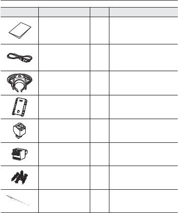
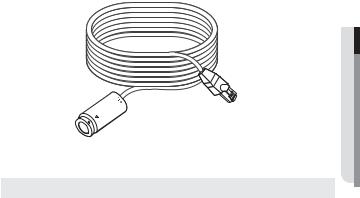
WHAT’S INCLUDED
Please check if your camera and accessories are all included in the product package.
Appearance |
Item Name |
Quantity |
Description |
|
Camera Unit |
1 |
Length: 8M |
|
Main Unit |
1 |
|
|
Instruction book, |
1 |
|
|
Installer S/W CD |
|
|
|
|
|
|
|
Quick Guide |
1 |
|
|
(Optional) |
|
|
|
|
|
OVERVIEW ●
English _11
overview
Appearance |
Item Name |
Quantity |
Description |
|
Warranty card |
1 |
|
|
(Optional) |
|
|
|
|
|
|
|
Cable for the testing monitor |
1 |
Used to test the camera connection to a |
|
portable display device |
||
|
|
|
|
|
Camera header installation |
1 |
Used to fix the camera header on the |
|
bracket |
ceiling/wall. |
|
|
|
||
|
Main unit installation bracket |
1 |
Used to install the main unit on the wall/ |
|
ceiling. |
||
|
|
|
|
|
Power terminal block |
1 |
Used by inserting it into the power terminal. |
|
Alarm terminal block |
1 |
Used by inserting it into the alarm output |
|
terminal. |
||
|
|
|
|
|
Installation screw |
4 |
Used to install the bracket on the |
|
wall/ceiling. |
||
|
|
|
|
|
Cable tie |
1 |
Used to arrange the cable. |
12_ overview
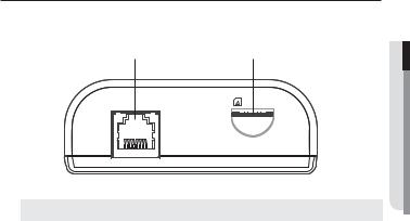
AT A GLANCE
Front of the main unit
b
&$0 |
PLFUR 6' |
|
Item |
Description |
Camera unit |
Using the RJ-12 cable, the terminal connects to the camera unit. |
connection terminal |
|
Micro SD Memory |
Compartment for the Micro SD memory card. |
b Card Compartment |
OVERVIEW ●
English _13
overview
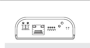
Rear of the main unit |
|
|
|
|
|
|
|
|
|
|
|
|
|
|
|
|
|
|
|
|
|
|
|
|
|
|
|
|
|
||||
|
|
|
|
b |
|
|
|
|
c |
|
|
|
|
|
|
||||||||||||||||||
|
|
|
|
|
1(7 |
|
25. |
|
|
|
|
|
|
|
|
|
|
|
|
|
32 |
(5 |
|
|
|
|
|
|
|
|
|||
|
|
|
|
|
|
/,1. |
|
$&7 |
|
|
|
|
|
|
|
|
|
|
|
|
|
|
|
|
|||||||||
|
|
|
|
|
|
|
|
|
|
|
|
|
|
|
|
|
|
|
|||||||||||||||
|
|
|
|
|
|
|
|
|
|
|
|
|
|
|
|
|
|
|
|
|
|
5(6(7 |
|
|
|
|
|
|
|
|
|
|
|
|
|
|
|
|
|
|
|
|
|
|
|
|
|
|
|
|
|
|
|
|
|
|
|
|
|
|
|
|
|
|
|
||
|
|
|
|
|
|
|
|
|
|
|
|
|
|
|
|
|
|
|
|
|
|
|
|
|
9,'(2 |
|
|
|
|||||
'& 9 |
|
|
|
|
|
|
|
|
|
|
|
|
|
|
|
|
|
|
|
|
|
|
|
||||||||||
|
|
|
|
|
|
|
*1' |
|
|
|
|
|
|
|
|
|
|
|
|
||||||||||||||
|
|
|
|
|
|
|
|
|
$/$50 287 |
|
|
|
|
|
|
|
|
|
|
||||||||||||||
|
|
|
|
|
|
|
|
|
$/$50 ,1 |
|
|
|
|
|
|
|
|
|
|
||||||||||||||
|
|
|
|
|
|
|
|
|
|
|
|
|
|
|
|
|
|
|
|
|
|
|
|
|
|
|
|
|
|
|
|
|
|
Item |
|
|
|
|
|
|
|
|
|
|
|
|
|
|
|
|
|
Description |
|
|
|||||||||||||
Power supply |
|
Terminal used to connect to the DC12V power adaptor. |
|
|
|||||||||||||||||||||||||||||
terminal |
|
|
|
||||||||||||||||||||||||||||||
b terminalNetwork connection |
|
Terminal used to connect to PoE or LAN via the RJ-45 cable. |
|||||||||||||||||||||||||||||||
|
|
|
|
|
GND |
|
Ground terminal. |
|
|
|
|
|
|
|
|
|
|
||||||||||||||||
c In/out terminal |
|
ALARM OUT |
The terminal sends the alarm output signal. |
||||||||||||||||||||||||||||||
|
Refer to “Alarm Out Wiring Diagram” (page 23). |
||||||||||||||||||||||||||||||||
|
|
|
|
|
ALARM IN |
|
The terminal sends the alarm input signal. |
||||||||||||||||||||||||||
|
|
|
|
|
|
Refer to “Alarm In Wiring Diagram” (page 22). |
|||||||||||||||||||||||||||
|
|
|
|
|
|
|
|
|
|||||||||||||||||||||||||
|
|
|
|
|
The button restores all camera settings to the factory default. |
||||||||||||||||||||||||||||
|
|
|
|
|
Press and hold for about 5 seconds to reboot the system. |
||||||||||||||||||||||||||||
Reset Button |
|
J If you reset the camera, the network settings will be adjusted so that |
|||||||||||||||||||||||||||||||
|
|
DHCP can be enabled. If there is no DHCP server in the network, you |
|||||||||||||||||||||||||||||||
|
|
|
|
|
|
must run the IP Installer program to change the basic network settings |
|||||||||||||||||||||||||||
|
|
|
|
|
|
such as IP address, Subnet mask, Gateway, etc., before you can |
|||||||||||||||||||||||||||
|
|
|
|
|
|
connect to the network. |
|
|
|
|
|
|
|
|
|
|
|
|
|
||||||||||||||
Power indicators |
|
POWER |
|
ON : While the power is on |
|
|
|||||||||||||||||||||||||||
|
|
OFF : If the power is off |
|
|
|||||||||||||||||||||||||||||
Test Monitor Out |
|
Output port for test monitoring the video output. Use the test monitor cable |
|||||||||||||||||||||||||||||||
|
to connect to a mobile display and check the test video. |
|
|
||||||||||||||||||||||||||||||
14_ overview
Exterior of the camera unit
OVERVIEW ●
|
|
|
|
|
|
|
|
|
|
|
|
|
|
b |
|||
|
|
|
|
|
|
Item |
|
|
|
Description |
|
Camera header |
|
|
Camera header used to record an image. |
||
|
|
|
|
|
|
b RJ-12 Jack |
|
|
Connect the main unit to the camera unit. |
||
English _15
installation & connection
INSTALLATION
Precautions before installation
Ensure you read out the following instructions before installing the camera:
•Select an installation site that can hold at least 5 times the camera’s weight.
•Stuck-in or peeled-off cables can cause damage to the product or a fire.
•For safety purposes, keep anyone else away from the installation site. And put aside personal belongings from the site, just in case.
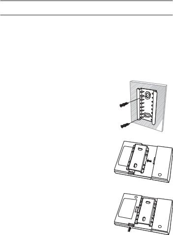
Installing the main unit
1. Using the two screws provided, install the main unit bracket.
2. Align the main unit’s groove to the bracket groove and firmly press it.
3. If you want to separate the main unit from the bracket, press the marked area in the figure.
16_ installation & connection
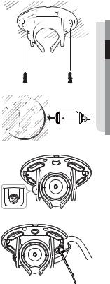
Installing the camera unit
1.Using the two screws provided or removing the double sided tape protector below the camera header bracket, install the header bracket.
2.Make sure that [TOP] shown in the lens head is faced upward, and then push the bracket in.
3.Considering the direction of monitoring, adjust the lens to make it face the desired direction.
4.Fasten the screw next to the bracket and fix the lens direction.
5.After installation, pull the cable. Make sure that the camera unit does not move by fixing it to the bracket with the cable tie.
TOP |
CONNECTION & INSTALLATION ● |
English _17

installation & connection
Installing the camera unit in the main unit
Connect the [CAM] terminal in the front of the main unit to the camera unit cable.
&$0 |
PLFUR 6' |
18_ installation & connection
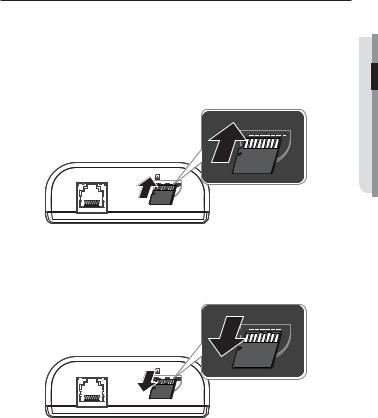
INSERTING/REMOVING A MICRO SD MEMORY CARD
JDisconnect the power cable from the camera before inserting the Micro SD memory card.
Do not insert the Micro SD memory card while it’s upside down by force. Otherwise, it may damage the Micro SD memory card.
Inserting a Micro SD Memory Card
Push the Micro SD memory card in the direction of the arrow shown in the diagram.
 PLFUR 6'
&$0 |
PLFUR 6' |
|
CONNECTION & INSTALLATION ●
Removing a Micro SD Memory Card
Gently press down on the exposed end of the memory card as shown in the diagram to eject the memory card from the slot.
 PLFUR 6'
&$0 |
PLFUR 6' |
English _19

installation & connection
JPressing too hard on the Micro SD memory card can cause the card to shoot out uncontrollably from the slot when released.
Before removing your Micro SD memory card, turn off the camera or go to <Storage>, turn the device off, and press the [Apply (  )] button. (Page 86)
If you turn off the camera or remove the Micro SD memory card that contains data from the product, the data may be lost or damaged.
MEMORY CARD INFORMATION (NOT INCLUDED)
What is a memory card?
The memory card is an external data storage device that has been developed to offer an entirely new way to record and share video, audio, and text data using digital devices.
Selecting a memory card that’s suitable for you
Your camera supports Micro SD/SDHC/SDXC memory cards.
You may, however, experience compatibility issues depending on the model and make of the memory card.
For your camera, we recommend you use a memory card from the following manufacturers:
Micro SD/SDHC/SDXC Memory Card : Sandisk, Transcend
Memory cards of 4GB ~ 64GB is recommended for using with this camera.
Playback performance can be affected depending on the speed of memory card, so use the high-speed memory card.
You are recommended to use memory card with class 6 or higher for this camera.
Memory Card Components
Contacts 


Micro SD/SDHC/SDXC
20_ installation & connection
CONNECTING WITH OTHER DEVICE
CONNECTION & INSTALLATION ●
Power
Ethernet
Monitor to install
JThe CVBS out terminal of the product is provided for easier installation, and is not recommended for monitoring purposes.
Ethernet Connection
Connect the Ethernet cable to the local network or to the Internet.
Power Supply
Use the screwdriver to connect each line (+, –) of the power cable to the corresponding power port of the camera.
JIfPoE.both PoE and DC12V are applied simultaneously, the product will be supplied with power from
-You can also use a router featuring PoE to supply power to the camera.
-Use PoE that is compliant with the IEEE802.3af protocols.
Be careful not to reverse the polarity when you connect the power cable.
If you want to connect an external device, you must turn off the external device before proceeding.
English _21
installation & connection
Power Cable Specification
In case of DC 12V Input:
Wire Type (AWG) |
|
#22 |
#20 |
|
#18 |
|
|
Cable Length (Max.) |
|
24m |
38m |
|
60m |
||
Network Cable Specification |
|
|
|
|
|
|
|
Item |
|
Contents |
|
Remark |
|
||
Connector |
|
RJ45 |
|
|
|
|
|
Ethernet |
|
10/100Base-T |
|
10/100 Mbps |
|
||
Cable |
|
UTP Category 5e |
|
|
|
|
|
Max Distance |
|
100M |
|
|
|
|
|
PoE Support |
|
IEEE 802.3af |
|
|
|
|
|
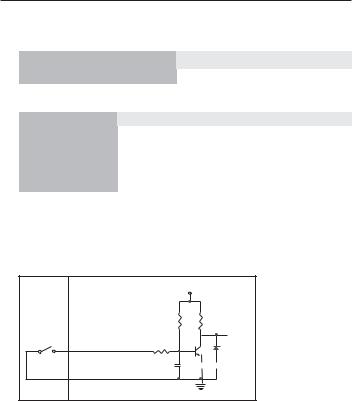
To connect the external sensor
Connect one strand of each signal line (2-strand) of the sensors to the [ALARM IN] port, and connect the other strand to the [GND] port.
Alarm In Wiring Diagram
External |
Inside of the camera |
|
VCC_3.3V |
connection |
|
|
|
|
|
RESISTOR |
RESISTOR |
Sensor |
ALARM IN (5mA SINK) |
RESISTOR |
DIODE |
|
|||
|
|
MLCC |
TRANSISTOR |
|
GND |
|
GND |
|
|
|
22_ installation & connection
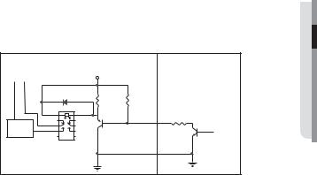
To connect the alarm out
If devices (e.g., flashing light and siren) that exceed the voltage and current specifications are connected by using the open collector method, it may cause malfunction.
Refer to the alarm out connection diagram below when connecting devices that exceed the voltage and current specifications.
Alarm Out Wiring Diagram
|
|
External connection |
Inside of the camera |
Warning lamp / Siren power |
DC 5V or 3.3V |
|
|
|
|
||
(-) |
(+) |
|
|
|
|
DIODE |
10K ohm |
|
|
RESISTOR |
|
|
|
TRANSISTOR |
ALARM OUT (12VDC 20mA MAX) |
|
|
|
|
Warning lamp / |
RELAY |
TRANSISTOR |
|
|
Siren |
|
|
|
|
|
GND |
|
|
GND |
GND |
|
|
|
|
CONNECTION & INSTALLATION ●
English _23
network connection and setup
You can set up the network settings according to your network configurations.
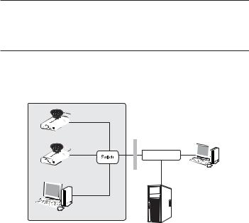
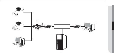
CONNECTING THE CAMERA DIRECTLY TO LOCAL AREA NETWORKING
Connecting to the camera from a local PC in the LAN
1.Launch an Internet browser on the local PC.
2.Enter the IP address of the camera in the address bar of the browser.
Camera |
|
|
|
|
INTERNET |
Camera |
Firewall |
External Remote PC |
Local PC |
|
DDNS Server |
|
(Data Center, KOREA) |
<Local Network>
MA remote PC in an external Internet out of the LAN network may not be able to connect to the camera installed in the intranet if the port-forwarding is not properly set or a firewall is set.
In this case, to resolve the problem, contact your network administrator.
In the IP installer, you can use the initial password, “4321” to set IP Address, Subnet Mask, Gateway, HTTP Port, VNP Port, IP type. After changing the network interface, for better security, access the web viewer and change the password.
By factory default, the IP address will be assigned from the DHCP server automatically. If there is no DHCP server available, the IP address will be set to 192.168.1.100.
To change the IP address, use the IP Installer.
For further details on IP Installer use, refer to “Static IP Setup”. (Page 29)
24_ network connection and setup
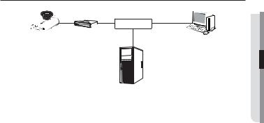
CONNECTING THE CAMERA DIRECTLY TO A DHCP BASED DSL/CABLE MODEM
INTERNET 
DSL/Cable Modem
Camera
External Remote PC
DDNS Server
(Data Center, KOREA)
1.Connect the user PC directly with the network camera.
2.Run the IP Installer and change the IP address of the camera so that you can use the web browser on your desktop to connect to the Internet.
3.Use the Internet browser to connect to the web viewer.
4.Move to [Setup] page.
5.Move to [Network] – [DDNS] and configure the DDNS settings.
6.Move to [Basic] – [IP & Port], and set the IP type to [DHCP].
7.Connect the camera, which was removed from your PC, directly to the modem.
8.Restart the camera.
MFor configuring the DDNS settings, refer to “DDNS”. (page 75)
For registering the DDNS settings, refer to “Registering with DDNS”. (page 76)
Refer to “IP & Port” for how to setup IP. (page 61)
SETUP AND CONNECTION NETWORK ●
English _25

network connection and setup
CONNECTING THE CAMERA DIRECTLY TO A PPPoE
MODEM
INTERNET 
PPPoE Modem
Camera
External Remote PC
DDNS Server
(Data Center, KOREA)
1.Connect the user PC directly with the network camera.
2.Run the IP Installer and change the IP address of the camera so that you can use the web browser on your desktop to connect to the Internet.
3.Use the Internet browser to connect to the web viewer.
4.Move to [Setup] page.
5.Move to [Network] – [DDNS] and configure the DDNS settings.
6.Move to [Basic] – [IP & Port] Setup Page, set the IP type to [PPPoE], and enter the network service’s ID and password.
7.Connect the camera, which was removed from your PC, directly to the modem.
8.Restart the camera.
MFor configuring the DDNS settings, refer to “DDNS”. (page 75)
For registering the DDNS settings, refer to “Registering with DDNS”. (page 76)
Refer to “IP & Port” for how to setup IP. (page 61)
26_ network connection and setup
CONNECTING THE CAMERA TO A BROADBAND ROUTER WITH THE PPPoE/CABLE MODEM
This is for a small network environment such as homes, SOHO and ordinary shops.
Camera |
|
|
|
|
|
|
INTERNET |
|
Broadband |
PPPoE or |
PPPoE or |
Camera |
Cable Modem |
Cable Modem |
|
Router |
|
External Remote PC |
DDNS Server
(Data Center, KOREA)
Local PC
Configuring the network settings of the local PC connected to a
Broadband Router
Configuring the network settings of the local PC connected to a Broadband Router, follow the instructions below.
•Select : <Network> <Properties> <Local Area Connection> <General>
<Properties> <Internet Protocol (TCP/IP)> <Properties> <Obtain an
IP address automatically> or <Use the following IP address>.
•Follow the instructions below if you select <Use the following IP address>: ex1) If the address (LAN IP) of the Broadband Router is 192.168.1.1
IP address : 192.168.1.100 Subnet Mask : 255.255.255.0 Default Gateway : 192.168.1.1
ex2) If the address (LAN IP) of the Broadband Router is 192.168.0.1 IP address : 192.168.0.100
Subnet Mask : 255.255.255.0 Default Gateway : 192.168.0.1
ex3) If the address (LAN IP) of the Broadband Router is 192.168.xxx.1 IP address : 192.168.xxx.100
Subnet Mask : 255.255.255.0 Default Gateway : 192.168.xxx.1
MFor the address of the Broadband Router, refer to the product’s documentation.
For more information about port forwarding of the broadband router, refer to “Port Range Forward (Port Mapping) Setup”. (Page 34)
SETUP AND CONNECTION NETWORK ●
English _27
network connection and setup
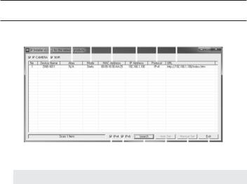
BUTTONS USED IN IP INSTALLER
b c
|
|
|
|
|
|
|
|
|
|
|
|
|
|
|
|
|
|
|
|
|
|
|
|
|
|
|
|
|
|
|
|
|
|
|
|
|
|
|
|
|
|
|
|
|
|
|
|
|
|
|
|
|
|
|
|
|
|
|
|
|
|
|
|
|
|
|
|
|
|
|
|
|
|
|
|
|
|
|
|
|
|
|
|
|
|
|
|
|
|
|
|
|
|
|
|
|
|
|
m |
||||||||
|
|
|
|
|
|
|
|
|
|
|
|
|
|
|
|
|
|
|
Item |
|
|
|
|
|
|
Description |
|
|
|
|
|||||
Device Name |
Model name of the connected camera. |
|
|
|
|
||||||||||||
Click the column to sort the list by model name. |
|||||||||||||||||
|
|
|
|
However, search will be stopped if clicked during the search. |
|||||||||||||
b Alias |
This function is not currently implemented. |
|
|
|
|
||||||||||||
c Mode |
Displays either <Static>, <Dynamic> or <PPPoE> for the current network |
||||||||||||||||
connection status. |
|
|
|
|
|
|
|
|
|||||||||
MAC(Ethernet) |
Ethernet address for the connected camera. |
|
|
|
|
||||||||||||
Click the column to sort the list by Ethernet address. |
|||||||||||||||||
|
Address |
However, search will be stopped if clicked during the search. |
|||||||||||||||
IP Address |
IP address. |
|
|
|
|
|
|
|
|
||||||||
Click the column to sort the list by IP address. |
|
|
|
|
|||||||||||||
|
|
|
|
However, search will be stopped if clicked during the search. |
|||||||||||||
Protocol |
Network setting for the camera. |
|
|
|
|
||||||||||||
The factory default is “IPv4”. |
|
|
|
|
|
|
|
|
|||||||||
|
|
|
|
Cameras with the IPv6 setting will be displayed “IPv6”. |
|||||||||||||
28_ network connection and setup

Item |
Description |
URL |
DDNS URL address enabling access from the external Internet. |
However, this will be replaced with the <IP Address> of the camera if |
|
|
DDNS registration has failed. |
IPv4 |
Scans for cameras with the IPv4 setting. |
IPv6 |
Scans for cameras with the IPv6 setting. |
Activated in an IPv6 compliant environment only. |
|
Search |
Scans for cameras that are currently connected to the network. |
However, this button will be grayed out if neither IPv4 nor IPv6 is checked. |
|
Auto Set |
The IP Installer automatically configures the network settings. |
Manual Set |
You should configure the network settings manually. |
m Exit |
Exits the IP Installer program. |
MFor the IP installer, use only the installer version provided in the installation CD or use the latest one if available. You can download the latest version from the Samsung web site (www.samsungcctv.com).
SETUP AND CONNECTION NETWORK ●
STATIC IP SETUP
Manual Network Setup
Run <IP Installer_v2.XX.exe> to display the camera search list.
At the initial startup, both [Auto Set] and [Manual Set] will be grayed out.
MFor cameras found with the IPv6 setting, these buttons will be grayed out as the cameras do not support this function.
1.Select a camera in the search list. Check the MAC address of the camera on the camera’s label.
Both the [Auto Set] and [Manual Set] buttons will be activated.
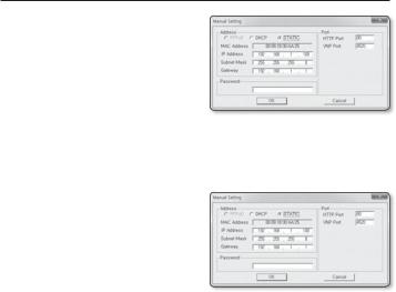
2.Click [Manual Set].
The Manual Setting dialog appears. <IP Address>, <Subnet Mask>,
<Gateway>, <HTTP Port>, and <VNP Port> of the camera are displayed in the preset values.
English _29
network connection and setup
3.In the <Address> pane, provide the necessary information.
•MAC (Ethernet) Address : The MAC address imprinted on the camera label is automatically displayed and requires no user setting.
MIP related parameters can be set only when DHCP is not checked.
If not using a Broadband Router
For setting <IP Address>, <Subnet Mask>, and <Gateway>, contact your network administrator.
4.In the <Port> pane, provide necessary information.
•HTTP Port : Used to access the camera using the Internet browser, defaulted to 80.
•VNP Port : Used to control the video signal transfer, defaulted to 4520.
5.Enter the password.
Enter the password of “admin” account, which was used to access the camera.
JFor the security purposes, you are recommended to use a combination of numbers, alphabets uppercase and lowercase and special characters for your password.
If you want to change the password, refer to “Administrator password change” of the user setup. (page 58)
6.Click [OK].
Manual network setup will be completed.
30_ network connection and setup
 Loading...