


SONOACE X6 Service Manual
ENGLISH
Document No. CSD-SMEX6
Revision 00
Copyright 2008 by MEDISON

Safety Requirements
Classifications:
-Type of protection against electrical shock: Class I
-Degree of protection against electrical shock (Patient connection):Type BF equipment
-Degree of protection against harmful ingress of water: Ordinary equipment
-Degree of safety of application in the presence of a flammable anesthetic material with air or with oxygen or nitrous oxide: Equipment not suitable for use in the presence of a flammable anesthetic mixture with air or with oxygen or nitrous oxide.
-Mode of operation: Continuous operation
Electromechanical safety standards met:
-IEC/EN 60601-1 Medical Electrical Eqiupment, Part 1General Requirements for Safety.
-IEC/EN 60601-1-1 Safety requirements for medicalelectrical systems.
-IEC/EN 60601-1-2 Electromagnetic compatibility -Requirements and tests.
-IEC/EN 60601-2-37 Particular requirements for the safety of ultrasonic medical diagnostic and monitoring equipment.
-IEC 61157 Declaration of acoustic output parameters.
-ISO 10993-1 Biological evaluation of medical devices.
-UL 2601-1 Medical Electrical Equipment, Part 1 General Requirements for Safety.
-CSA 22.2, 601.1 Medical Electrical Equipment, Part 1 General Requirements for Safety.

Declarations;
 0123
0123
This is CSA symbol for Canada and United States of America
This is manufacturer’s declaration of product compliance with applicable EEC directive(s) and the European notified body.
This is manufacturer’s declaration of product compliance with applicable EEC directive(s).

READ THIS FIRST
Before asking for the product to be repaired, read this service manual thoroughly, learn how to troubleshoot, and make sure you understand the precautions fully.
The repair of the system and the replacement of parts must be carried out by an authorized dealer or the customer care department of MEDISON Co., Ltd.
Thecompanyshallnotbeheld liablefor any injuryanddamagecausedby notfollowing this warning.
For safe use of this product, you should read ‘Chapter 2. Safety’ in this manual, prior to starting
to useing this system.
DANGER
WARNING
CAUTION
NOTE
Describes precautions necessary to prevent user hazards of great urgency. Ignoring a DANGER warning will risk life-threatening injury.
Used to indicate the presence of a hazard that can cause serious personal injury, or substantial property damage.
Indicates the presence of a hazard that can cause equipment damage.
A piece of information useful for installing, operating and maintaining a system. Not related to any hazard.
`````Contents
Chapter 1. |
General Information |
1-1 |
|
1.1 |
Overview |
1-1 |
|
1.2 |
Features and Advantages of SONOACE X6 |
1-2 |
|
1.3 |
Product Configuration |
1-3 |
|
|
1.3.1 |
Console |
1-3 |
|
1.3.2 |
LCD Monitor |
1-5 |
|
1.3.3 |
Control Panel |
1-6 |
|
1.3.4 |
Probe |
1-7 |
1.4 |
Specifications |
1-8 |
|
Chapter 2. |
Safety |
|
2-1 |
2.1 |
Overview |
2-1 |
|
2.2 |
Safety – Related Information |
2-2 |
|
|
2.2.1 |
Safety Symbols |
2-2 |
|
2.2.2 |
Label |
2-4 |
2.3 |
Electrical Safety |
2-6 |
|
|
2.3.1 |
Prevention Electric Shock |
2-6 |
|
2.3.2 |
ECG - Related Information |
2-7 |
|
2.3.3 |
ESD |
2-8 |
|
2.3.4 |
EMI |
2-8 |
|
2.3.5 |
EMC |
2-9 |
2.4 |
Mechanical Safety |
2-15 |
|
|
2.4.1 |
Moving the Equipment |
2-15 |
|
2.4.2 |
Safety Note |
2-16 |
2.5 |
Biological Safety |
2-17 |
|
|
2.5.1 |
ALARA Principle |
2-17 |
2.6 |
Environmental Protection |
2-29 |
|
Contents
Contents
Chapter 3. Installing the Product |
3-1 |
||
3.1 |
Overview |
3-1 |
|
3.2 |
Transportation |
3-3 |
|
|
3.2.1 |
Precautions for Transportation |
3-3 |
|
3.2.2 |
Temperature and Humidity |
3-3 |
|
3.2.3 Transportation of the Product |
3-4 |
|
3.3 |
Unpacking |
3-5 |
|
|
3.3.1 |
Unpacking the Box |
3-5 |
|
3.3.2 |
Checking Package Contents |
3-6 |
3.4 |
Precautions for Installation |
3-7 |
|
|
3.4.1 |
Precautions |
3-7 |
|
3.4.2 |
Installation Location |
3-8 |
3.5 |
Installation Procedure |
3-9 |
|
|
3.5.1 |
Installation Safety |
3-9 |
|
3.5.2 Connecting the Power Cord |
3-10 |
|
|
3.5.3 Connecting the Network Cable |
3-11 |
|
|
3.5.4 Connecting the Foot switch |
3-11 |
|
|
3.5.5 |
Connecting the Probe |
3-12 |
3.6 |
Starting the Product |
3-13 |
|
3.7 |
Shutting down the Product |
3-15 |
|
|
3.7.1 |
Power Switch |
3-15 |
|
3.7.2 |
Cut-off Switch |
3-15 |
3.8 |
Connecting the Peripherals |
3-16 |
|
|
3.8.1 |
BW Printer |
3-16 |
|
3.8.2 |
Color Printer |
3-17 |
|
3.8.3 |
Line Printer |
3-18 |
|
3.8.4 |
VCR |
3-18 |
|
3.8.5 |
USB Storage Device |
3-19 |
3.9 |
System Setting |
3-20 |
|
|
3.9.1 |
General System Setup |
3-20 |
|
3.9.2 |
Display Setup |
3-22 |
|
3.9.3 |
Misc |
3-24 |
|
3.9.4 |
Peripherals Setup |
3-25 |
|
3.9.5 |
Information |
3-26 |
|
3.9.6 |
DICOM Setup (Option) |
3-27 |
|
3.9.7 |
Option Setup |
3-34 |
Contents
Contents
Chapter 4. Checking the Product |
4-1 |
||
4.1 |
Overview |
4-1 |
|
4.2 |
Starting the Product |
4-2 |
|
4.3 |
Monitor |
|
4-6 |
|
4.3.1 |
Monitor Display |
4-4 |
4.4 |
Control Panel |
4-6 |
|
|
4.4.1 |
Power On/Off |
4-6 |
|
4.4.2 |
Starting and Finishing Exam |
4-6 |
|
4.4.3 |
Selecting Diagnosis mode and Gain Control |
4-7 |
|
4.4.4 |
Image Adjustment |
4-9 |
|
4.4.5 |
TGC |
4-10 |
|
4.4.6 |
Measurement and Annotation |
4-10 |
|
4.4.7 |
Trackball and its related control |
4-11 |
|
4.4.8 |
SONOVIEW and Report |
4-12 |
|
4.4.9 |
Save and Print |
4-12 |
|
4.4.10 |
Alphanumeric keyboard |
4-13 |
|
4.4.11 |
Flexible Soft Buttons |
4-13 |
|
4.4.12 |
Function Buttons |
4-14 |
4.5 |
Checking the Performance |
4-15 |
|
|
4.5.1 |
Basic Check |
4-15 |
|
4.5.2 |
Detail Check |
4-16 |
Contents
Contents
Chapter 5. |
Product Structure |
5-1 |
|
5.1 |
Overview |
5-1 |
|
5.2 |
System Block Diagram |
5-3 |
|
5.3 |
Basic Structure of SONOACE X6 |
5-4 |
|
|
5.3.1 |
Overview |
5-4 |
|
5.3.2 |
Ultrasound System Part |
5-5 |
|
5.3.3 |
User Interface Part |
5-5 |
|
5.3.4 |
Power Part |
5-5 |
5.4 |
PSA |
|
5-6 |
5.5 |
Front End Board |
5-9 |
|
5.6 |
CW Board |
5-13 |
|
5.7 |
Back End Board |
5-15 |
|
5.8 |
Rear Board |
5-22 |
|
5.9 |
Control Panel |
5-23 |
|
5.10 Power Supply |
5-24 |
||
Chapter 6. |
Basic Maintenance |
6-1 |
|
6.1 |
Overview |
6-1 |
|
6.2 |
System Information |
6-2 |
|
6.3 |
Entering Admin Mode |
6-3 |
|
6.4 |
Upgrade |
6-6 |
|
|
6.4.1 |
Software Upgrade |
6-6 |
|
6.4.2 |
Hardware Upgrade |
6-9 |
6.5 |
Backup & Restore |
6-10 |
|
|
6.5.1 |
Backup User Setting |
6-10 |
|
6.5.2 |
Restore User Setting |
6-11 |
6.6 Adding and Deleting Options |
6-13 |
||
|
6.6.1 |
Option type |
6-13 |
|
6.6.2 |
Registering Options |
6-13 |
|
6.6.3 |
Deleting Options |
6-14 |
6.7 |
Control Panel Test |
6-15 |
|
Contents
Contents
Chapter 7. |
Troubleshooting |
7-1 |
|
7.1 |
Overview |
7-1 |
|
7.2 |
Power |
|
7-2 |
|
7.2.1 |
Power Failure |
7-2 |
|
7.2.2 Power cannot be turned off |
7-2 |
|
|
7.2.3 Power is automatically turned off |
7-3 |
|
7.3 |
Monitor |
|
7-4 |
|
7.3.1 |
Blank Screen |
7-4 |
|
7.3.2 Screen Color is Abnormal |
7-4 |
|
7.4 |
Error Messages |
7-5 |
|
|
7.4.1 System hangs after an error during booting |
7-5 |
|
|
7.4.2 System works even if error occurred |
7-5 |
|
|
7.4.3 |
Error code |
7-5 |
7.5 |
Image |
|
7-6 |
|
7.5.1 No BW Image Echo |
7-6 |
|
|
7.5.2 No BW Mode Image Format |
7-6 |
|
|
7.5.3 Noise Link Rain over the BW Mode Image (Noise) |
7-6 |
|
|
7.5.4 PW Doppler Mode Trouble |
7-7 |
|
|
7.5.5 CW Doppler Mode Trouble |
7-7 |
|
|
7.5.6 Color Doppler Mode Trouble |
7-7 |
|
|
7.5.7 |
Motion Mode Trouble |
7-7 |
Contents
Contents
Chapter 8. Disassembly and Reassembly |
8-1 |
||
8.1 |
Overview |
8-1 |
|
8.2 |
Disassembly and Reassembly of the External Case |
8-4 |
|
|
8.2.1 |
Preparations |
8-4 |
|
8.2.2 |
Cover Front Lower |
8-4 |
|
8.2.3 |
Cover Top Plate |
8-5 |
|
8.2.4 |
Cover Rear Lower |
8-6 |
8.3 |
Disassembly and Reassembly of the LCD Monitor |
8-7 |
|
|
8.3.1 |
Preparations |
8-7 |
|
8.3.2 |
LCD Monitor |
8-7 |
|
8.3.3 |
LCD Monitor Arm |
8-8 |
8.4 |
Disassembly and Reassembly of the Ultrasound System PCB Part |
8-9 |
|
|
8.4.1 |
Preparations |
8-9 |
|
8.4.2 |
PSA ASSY |
8-9 |
|
8.4.3 CW Board, FE Board, BE Board |
8-10 |
|
|
8.4.4 DC to DC Power Module |
8-11 |
|
8.5 |
Disassembly and Reassembly of the HDD & DVD |
8-12 |
|
|
8.5.1 |
Preparations |
8-12 |
|
8.5.2 |
HDD & DVD |
8-12 |
8.6 |
Disassembly and Reassembly of the Rear Panel |
8-13 |
|
|
8.6.1 |
Preparations |
8-13 |
|
8.6.2 Rear Right Board & Rear Left Board |
8-13 |
|
|
8.6.3 |
Back Fan |
8-14 |
8.7 |
Disassembly and Reassembly of the Power Supply |
8-16 |
|
|
8.7.1 |
Preparations |
8-16 |
|
8.7.2 AC to DC Power Module |
8-16 |
|
|
8.7.3 DC to DC Power Module |
8-16 |
|
8.8 |
Disassembly and Reassembly of the Control Panel |
8-17 |
|
|
8.8.1 |
Preparations |
8-17 |
|
8.8.2 |
Control Panel |
8-17 |
|
8.8.3 |
Key Matrix Board |
8-18 |
|
8.8.4 |
Track Ball |
8-19 |
|
8.8.5 |
Alpha Numeric Keyboard |
8-20 |
|
8.8.6 |
Speaker |
8-20 |
Contents
Content
Chapter 9. |
Probe |
|
9-1 |
9.1 |
Overview |
9-1 |
|
9.2 |
Probe List |
9-2 |
|
9.3 |
Thermal Index (TI Table) |
9-3 |
|
9.4 |
Ultrasound Transmission Gel |
9-4 |
|
9.5 |
Sheaths |
|
9-5 |
9.6 |
Probe Precautions |
9-5 |
|
9.7 |
Cleaning and Disinfecting the Probe |
9-8 |
|
Chapter 10. |
User Maintenance |
10-1 |
|
10.1 |
Overview |
10-1 |
|
10.2 |
System Maintenance |
10-2 |
|
|
10.2.1 |
Installation Maintenance |
10-2 |
|
10.2.2 |
Cleaning and Disinfections |
10-3 |
|
10.2.3 Fuse Replacement |
10-5 |
|
|
10.2.4 Cleaning the Air Filter |
10-6 |
|
|
10.2.5 Accuracy Check |
10-6 |
|
10.3 |
Administration of Information |
10-7 |
|
|
10.3.1 User Setting Back-up |
10-7 |
|
|
10.3.2 |
Patient Information Back-up |
10-7 |
|
10.3.3 Software |
10-7 |
|
Chapter 11. ServicePart List |
11-1 |
||
11.1 |
Overview |
11-1 |
|
11.2 |
Cover |
|
11-2 |
11.3 |
Ultrasound System Part |
11-4 |
|
11.4 |
Rear Plan |
11-5 |
|
11.5 |
Power Part |
11-6 |
|
11.6 |
LCD Monitor |
11-7 |
|
11.7 |
Control Panel |
11-9 |
|
11.8 |
Probe |
|
11-10 |
Contents
1General Information
1.1Overview
Chapter1containstheinformationnecessarytoplantheTroubleshootingofSONOACEX6
TheSONOACE X6 isahigh-resolutioncolor ultrasoundsystemwith high penetration andavarietyofmeasurement functions
Contents General Information
1.1 |
Overview |
1-1 |
|
1.2 |
Features and Advantages of SONOACE X6 |
1-2 |
|
1.3 |
Product Configuration |
1-3 |
|
|
1.3.1 |
Console |
1-3 |
|
1.3.2 |
LCD Monitor |
1-5 |
|
1.3.3 |
Control Panel |
1-6 |
|
1.3.4 |
Probes |
1-7 |
1.4 |
Specifications |
1-8 |
|
Chapter 1. General Information 1-1

1.2Features and Advantages of SONOACE X6
y |
High-endDigitalBeamforming:The SONOACEX6utilizesthenewly developed |
|
DigitalBeam formingtechnology. |
y |
A variety of applications : The SONOACE X6 is optimized for use in a variety of |
|
ultrasound departments, including general, abdomen, obstetrics, gynecology, |
|
vascular, extremity, pediatric, cardiac, breast, urology, and etc. |
yVarious diagnostic Modes : 2D Mode, M Mode, Color Doppler Mode, Power Doppler Mode, PW Spectral Doppler Mode, CW Spectral Doppler Mode(Option), etc.
y3D images can be obtained.
yMeasurement and Report Functions : Besides the basic distance, area,
circumference and volume measurement functions, the SONOACE X6 also provides application-specific measurement functions. The report function collates measurement data.
y Review of Scanned Images : The SONOACE X6 displays Cine images of 512 frames and loop images of 4096 lines.
ySonoViewTM : This is a total ultrasound image management system, which allows a user to archive, view and exchange documents.
yDigital Imaging and Communications in Medicine (DICOM) Function : This is used to archive, transmit and print DICOM images through a network.
yPeripheral/Accessory Connection : A variety of peripheral devices including VCRs and printers can be easily connected to the SONOACE X6.
Chapter 1. General Information 1-2
1.3Product Configuration
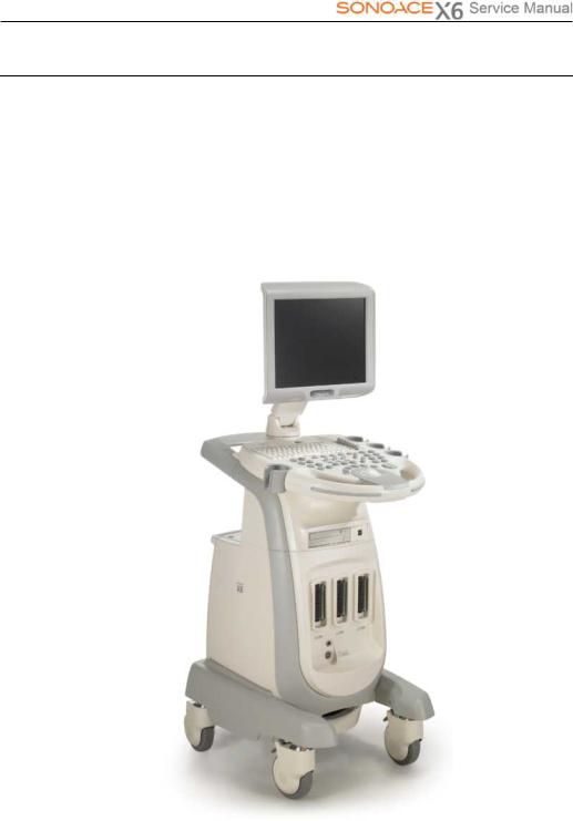
This Product consists of the monitor, the control panel, the console and the probes.
1.3.1Console
Theconsoleconsistsoftwoparts–the inner unitandtheouterunit.
Theinterioroftheconsolemainlycontainsdevicesthat produceultrasoundimages. Ontheexterioroftheconsole iscomposed ofvariousconnectors, probeholders, storagecompartments,handles,wheels,etc.
 LCD Monitor
LCD Arm 
 Control Panel
DVD-RW Drive 
 Probe Connector
Pencil probe Connector 
 Wheel
Wheel
[Figure 1-1] Console of SONOACE X6
Chapter 1. General Information 1-3
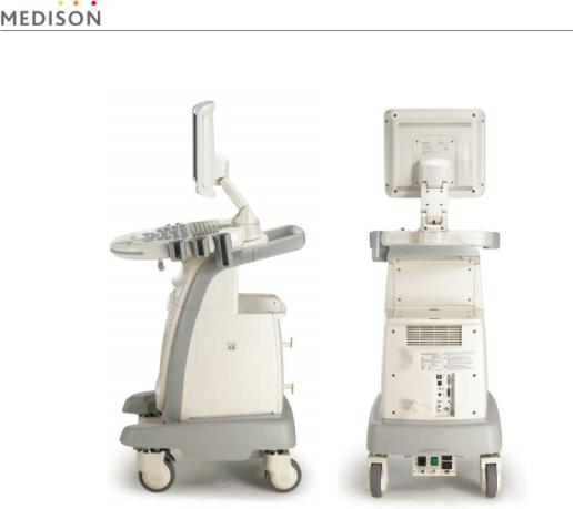
[Figure 1-2] Rear and side of SONOACE X6
Chapter 1. General Information 1-4
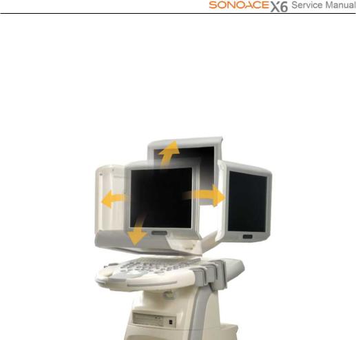
1.3.2LCDMonitor
The LCD monitor of this system is a color VGA monitor, which displays ultrasound images and additional information. Use the monitor arm to adjust the height or position of the monitor.
[Figure 1-3] LCD Arm
Chapter 1. General Information 1-5
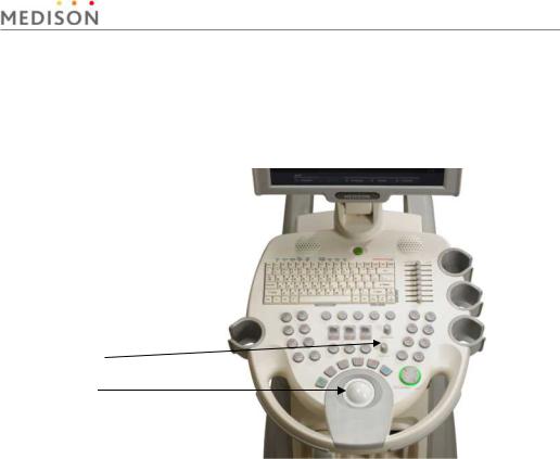
1.3.3Control Panel
The control panel can be used for controlling the system. It consists of the following four sections:
Alphanumerics Keyboard 
Slide Volume 
Button 
Dial Button
Track Ball
[Figure 1-4] Control Panel
Chapter 1. General Information 1-6

1.3.4Probe
Probes are devices that generate ultrasound waves and process reflected wave data for the purpose of image formation.
NOTE For more information, refer to `Chapter 9 Probes’.
Chapter 1. General Information 1-7

1.4Specifications
|
|
|
|
Height: 1378mm (with monitor) |
|
|
Physical Dimensions |
|
|
Width: 483mm |
|
|
|
|
Depth: 691mm |
|
|
|
|
|
|||
|
|
|
|
Weight: More than 60.75kg |
|
|
|
|
|
|
|
|
Monitor |
15 inch LCD monitor |
|||
|
|
|
|
||
|
Electrical Parameters |
|
|
100-120V/200-240VAC, 8/5A, 50/60Hz |
|
|
|
|
|
|
|
|
Pressure Limits |
|
Operating: 700hPa to 1060hPa |
||
|
|
Storage: 700hPa to 1060hPa |
|||
|
|
|
|
||
|
|
|
|
|
|
|
Humidity Limits |
|
|
Operating: 30% to 75% |
|
|
|
|
Storage & Shipping: 20% to 90% |
|
|
|
|
|
|
|
|
|
|
|
|
|
|
|
Temperature Limits |
|
Operating: 10OC ~ 35OC |
||
|
|
Storage & Shipping: -25OC ~ 60OC |
|||
|
|
|
|
||
|
|
|
|
|
|
|
|
|
|
2D imaging mode |
|
|
|
|
|
Dual 2D imaging mode |
|
|
|
|
|
M imaging mode |
|
|
|
|
|
2D/M imaging mode |
|
|
Imaging modes |
|
|
Color Doppler Imaging (CDI) mode |
|
|
|
|
Power Doppler Imaging (PDI) mode |
|
|
|
|
|
|
|
|
|
|
|
|
Pulse Wave (PW) Spectral Doppler imaging mode |
|
|
|
|
|
Continuous Wave (CW) Spectral Doppler imaging mode |
|
|
|
|
|
3D imaging mode (Freehand) |
|
|
|
|
|
Simultaneous mode |
|
|
|
|
|
|
|
|
|
|
|
Transmit focusing, maximum of eight points (four points |
|
|
Focusing |
|
simultaneously selectable) |
||
|
|
|
|
Digital dynamic receive focusing (continuous) |
|
|
|
|
|
|
|
|
|
|
|
General, Gynecology, Abdomen, OB, Renal, Urology, Vascular, |
|
|
Application |
|
|
Small Part, Fetal Heart, Breast, Musculoskeletal, Pediatric, Cardiac, |
|
|
|
|
|
TCD, Neonatal |
|
|
|
|
|
|
|
Chapter 1. General Information 1-8

|
|
|
|
Trackball operation of multiple cursors |
|
|
|
Measurement |
|
2D: Linear measurements and area measurements using elliptical |
|
||
|
|
approximation or trace |
|
|||
|
|
|
|
|
||
|
Packages |
|
M-mode: Continuous readout of distance, time, and slope rate |
|
||
|
|
|
|
|
||
|
|
|
|
Doppler: Velocity and trace |
|
|
|
|
|
|
|
|
|
|
|
|
|
Maximum 512 frames for CINE memory |
|
|
|
Image Storage |
|
|
Maximum 4096 Lines for LOOP memory |
|
|
|
|
|
|
Image filing system |
|
|
|
|
|
|
|
|
|
|
Gray Scale |
|
256 (8 bits) |
|
||
|
|
|
|
|
|
|
|
|
|
|
TGC control |
|
|
|
|
|
|
Mode-independent gain control |
|
|
|
|
|
|
Acoustic power control (adjustable) |
|
|
|
|
|
|
Dynamic aperture |
|
|
|
|
|
|
Dynamic apodization |
|
|
|
Signal processing |
|
|
Dynamic range control (adjustable) |
|
|
|
|
|
Image view area control |
|
|
|
|
(Pre-processing) |
|
|
|
|
|
|
|
|
M-mode sweep speed control |
|
|
|
|
|
|
|
|
|
|
|
|
|
|
HD zoom |
|
|
|
|
|
|
Frame average |
|
|
|
|
|
|
Gamma-scale windowing |
|
|
|
|
|
|
Image orientation (left/right and up/down) |
|
|
|
|
|
|
White on black/black on white |
|
|
|
|
|
|
|
|
|
|
|
|
|
Curved Linear Array |
|
|
|
|
|
|
C3-7EP |
|
|
|
|
|
|
C4-9ED |
|
|
|
|
|
|
Linear Array |
|
|
|
|
|
|
HL5-12ED |
|
|
|
|
|
|
L5-12/50EP |
|
|
|
Probes |
|
Endocavity Curved Linear Array |
|
||
|
|
NER4-9ES |
|
|||
|
|
|
|
|
||
|
|
|
|
NEV4-9ES |
|
|
|
|
|
|
Phased Array |
|
|
|
|
|
|
P2-4AH |
|
|
|
|
|
|
CW |
|
|
|
|
|
|
CW2.0 |
|
|
|
|
|
|
CW4.0 |
|
|
|
|
|
|
|
|
|
|
|
|
|
Chapter 1. General Information 1-9 |
||
|
|
|
Three probe connectors |
|
Probe connections |
|
Four probe connectors for option |
|
|
|
Including one CW probe connector. |
|
|
|
|
|
|
|
VHS and S-VHS VCR left and right audio |
|
|
|
ECG |
|
Rear Panel |
|
Microphone |
|
|
Patient monitor video and 9V dc power |
|
|
Input / Output |
|
|
|
|
B/W printer video and remote control |
|
|
Connections |
|
|
|
|
VGA monitor |
|
|
|
|
|
|
|
|
Parallel port |
|
|
|
USB |
|
|
|
|
|
|
|
Black-and white printer |
|
|
|
Color printer |
|
Auxiliary |
|
VCR |
|
|
|
Monitor |
|
|
|
Foot switch |
|
|
|
|
Chapter 1. General Information 1-10
2Safety
2.1Overview
Chapter 2 contains the information necessary to Safety.
Contents Safety |
|
|
|
2.1 |
Overview |
2-1 |
|
2.2 |
Safety – Related Information |
2-2 |
|
|
2.2.1 |
Safety Symbols |
2-2 |
|
2.2.2 |
Label |
2-4 |
2.3 |
Electrical Safety |
2-6 |
|
|
2.3.1 |
Prevention Electric Shock |
2-6 |
|
2.3.2 |
ECG - Related Information |
2-7 |
|
2.3.3 |
ESD |
2-8 |
|
2.3.4 |
EMI |
2-8 |
|
2.3.5 |
EMC |
2-9 |
2.4 |
Mechanical Safety |
2-15 |
|
|
2.4.1 |
Moving the Equipment |
2-15 |
|
2.4.2 |
Safety Note |
2-16 |
2.5 |
Biological Safety |
2-17 |
|
|
2.5.1 |
ALARA Principle |
2-17 |
2.6 |
Environmental Protection |
2-29 |
|
Chapter 2. Safety 2-1
2.2Safety - Related Information
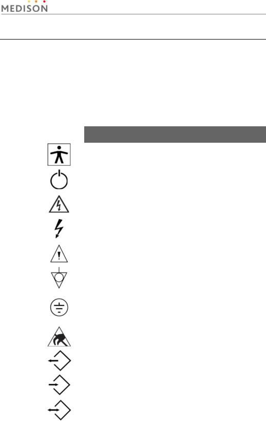
2.2.1Safety Symbols
The International Electro Technical Commission (IEC) has established a set of symbols for medical electronic equipment, which classifies a connection or warn of potential hazards. The classifications and symbols are shown below.
Symbols |
Description |
|
|
|
Isolated patient connection (Type BF applied part). |
|
|
|
Power switch (Supplies/cuts the power for product) |
|
|
|
Indicates a caution for risk of electric shock. |
|
|
|
Indicates dangerous voltages over 1000V AC or over |
|
1500V DC. |
|
|
|
Warning, Caution |
|
|
|
Identifies an equipotential ground. |
|
|
|
Identifies the point where the system safety ground is |
|
fastened to the chassis. Protective earth connected to |
|
conductive parts of Class I equipment for safety |
|
purposes. |
|
|
|
Electrostatic discharge |
|
|
|
Data Output port |
|
|
|
Data Input port |
|
|
|
Data Input/Output port |
|
|
Chapter 2. Safety 2-2
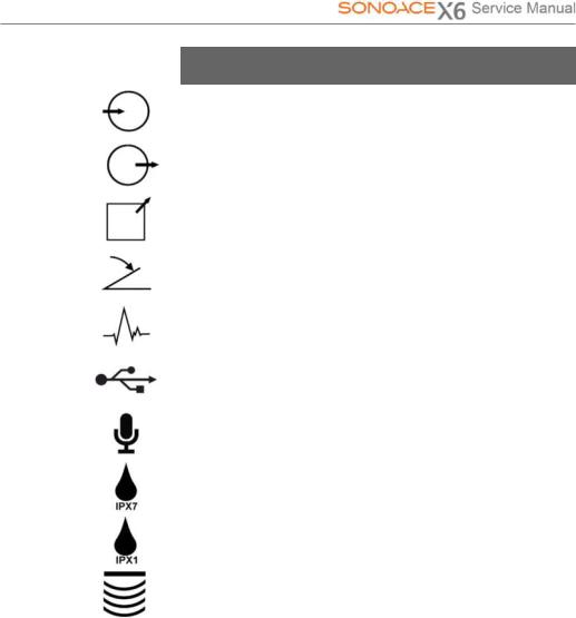
Symbols |
Description |
|
|
|
Left and right Audio / Video input |
|
|
|
Left and right Audio / Video output |
|
|
|
Print remote output |
|
|
|
Foot switch connector |
|
|
|
ECG connector |
|
|
|
USB connector |
|
|
|
Microphone connector |
|
|
|
Protection against the effects of immersion. |
|
|
|
Protection against dripping water. |
|
|
|
Probe connector |
|
|
Chapter 2. Safety 2-3
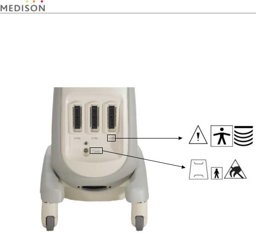
2.2.2Labels
To protect the system, you may see ‘Warning’ or ‘Caution’ marked on the surface of the product
1) Front
[Figure 2-1] Labels of Front
Chapter 2. Safety 2-4

2) Rear
[ Figure 2-2] Labels of Rear
Chapter 2. Safety 2-5
2.3Electrical Safety
This equipment has been verified as a Class I device with Type BF applied parts.
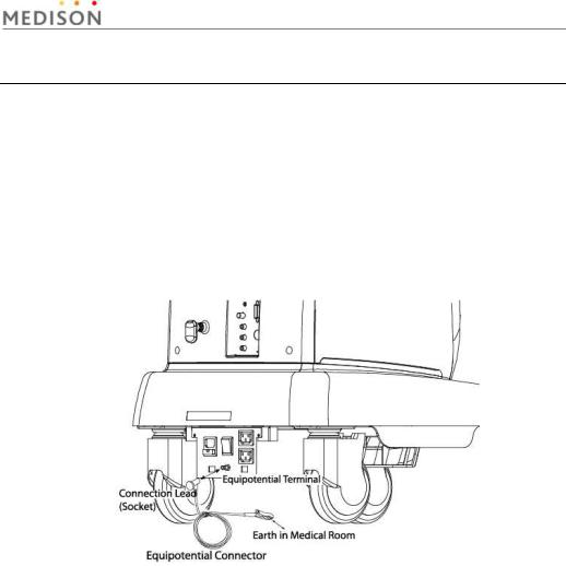
2.3.1Prevention of Electric Shock
In a hospital, dangerous currents are due to the potential differences between connected equipment and touchable conducting parts found in medical rooms. The solution to the problem is consistent equipotential bonding. Medical equipment is connected with connecting leads made up of angled sockets to the equipotential bonding network in medical rooms.
[Figure 2-3] Equipotential bonding
Additional equipment connected to medical electrical equipment must comply with the respective IEC or ISO standards (e.g. IEC 60950 for data processing equipment). Furthermore all configurations shall comply with the requirements for medical electrical systems (see IEC 60601-1-1 or clause 16 of the 3 Ed. of IEC 60601-1, respectively). Anybody connecting additional equipment to medical electrical equipment configures a medical system and is therefore responsible that the system complies with the requirements for medical electrical systems. Attention is drawn to the fact that local laws take priority over the above-mentioned requirements. If in doubt, consult your local distributor or the technical service department.
Chapter 2. Safety 2-6
WARNING
CAUTION
yElectric shock may exist result if this system, including and all of its externally mounted recording and monitoring devices, is not properly grounded.
yDo not remove the covers on the system; hazardous voltages are present inside. Cabinet panels must be in place while the system is in use. All internal adjustments and replacements must be made by a qualified MEDISON Customer Service Department.
yCheck the face, housing, and cable before use. Do not use, if the face is cracked, chipped, or torn, the housing is damaged, or if the cable is abraded.
yAlways disconnect the system from the wall outlet prior to cleaning the system.
yAll patient contact devices, such as probes and ECG leads, must be removed from the patient prior to application of a high voltage defibrillation pulse.
yThe use of flammable anesthetic gas or oxidizing gases (N20) should be avoided.
yThe system has been designed for 100-120VAC and 200-240VAC; you should select the input voltage of monitor, printer and VCR. Prior to connecting an OEM power cord, verify that the voltage indicated on the power cord matches the voltage rating of the OEM device.
yAn isolation transformer protects the system from power surges. The isolation transformer continues to operate when the system is in standby.
yDo not immerse the cable in liquids. Cables are not waterproof.
yThe operator does not contact the parts (SIP/SOP) and the patient simultaneously
2.3.2ECG-Related Information
WARNING y This device is not intended to provide a primary ECG monitoring function, and therefore does not have means of indicating an inoperative
electrocardiograph.
yDo not use ECG electrodes of HF surgical equipment. Any malfunctions in the HF surgical equipment may result in burns to the patient.
yDo not use ECG electrodes during cardiac pacemaker procedures or other electrical stimulators.
yDo not use ECG leads and electrodes in an operating room.
Chapter 2. Safety 2-7
2.3.3ESD
Electrostatic discharge (ESD), commonly referredto as a static shock, is a naturally occurring phenomenon. ESD is most prevalent during conditions of low humidity, which can be caused by heating or air conditioning. During low humidity conditions, electrical charges naturally build up on individuals, creating static electricity. An ESD occurs when an individual with an electrical energy build-up comes in contact with conductive objects such as metal doorknobs, file cabinets, computer equipment, and even other individuals. The static shock or ESD is a discharge of the electrical energy build-up from a charged individual to a lesser or non-charged individual or object.
The ESD caution symbol is on the probe connector and the rear panel.
[Figure 2-4] ESD symbol
CAUTION y The level of electrical energy discharged from a system user or patient to an ultrasound system can be significant enough to cause
damage to the system or probes.
yThe following precautions can help to reduce ESD:
-Anti-static sprays on carpets or linoleum
-Anti-static mats
-A ground wire connection between the system and the patient table or bed.
2.3.4EMI
Although this system has been manufactured in compliance with existing EMI (Electromagnetic Interference) requirements, use of this system in the presence of an electromagnetic field can cause momentary degradation of the ultrasound image.
If this occurs often, MEDISON suggests a review of the environment in which the system is being used, to identify possible sources of radiated emissions. These emissions could be from other electrical devices used within the same room or an adjacent room. Communication devices such as cellular phones and pagers can cause these emissions. The existence of radios, TVs, or microwave transmission equipment nearby can also cause interference.
Chapter 2. Safety 2-8
CAUTION In cases where EMI is causing disturbances, it may be necessary to relocate this system.
2.3.5EMC
The testing for EMC(Electromagnetic Compatibility) of this system has been performed according to the international standard for EMC with medical devices (IEC60601-1-2). This IEC standard was adopted in Europe as the European norm (EN60601-1-2).
2.3.5.1Guidance and manufacturer’s declaration - electromagnetic emission
This product is intended for use in the electromagnetic environment specified below. The customer or the user of this product should assure that it is used in such an environment.
|
Emission test |
|
Compliance |
|
Electromagnetic environment -guidance |
|
|
|
|
|
|
|
RF Emission |
|
Group 1 |
|
The Ultrasound System uses RF energy only |
|
(Radiation) |
|
|
for its internal function. Therefore, its RF |
|
|
|
Class B |
|
||
|
CISPR 11 |
|
|
emissions are very low and are not likely to |
|
|
|
|
|
||
|
|
|
|
|
cause any interference in nearby electronic |
|
RF Emission |
|
Group 1 |
|
|
|
(Radiation) |
|
|
equipment. |
|
|
|
Class B |
|
||
|
CISPR 11 |
|
|
The Ultrasound System is suitable for use in |
|
|
|
|
|
||
|
|
|
|
|
all establishments, including domestic |
|
Harmonic Emission |
|
Class A |
|
|
|
IEC 61000-3-2 |
|
|
establishments and those directly connected |
|
|
|
|
|
||
|
|
|
|
|
to the public low-voltage power supply |
|
Flicker Emission |
|
|
|
|
|
|
Complies |
|
network that supplies building used for |
|
|
IEC 61000-3-3 |
|
|
||
|
|
|
|
domestic purpose. |
|
|
|
|
|
|
|
|
|
|
|
|
|
Chapter 2. Safety 2-9
 Loading...