


NETWORK CAMERA
User Manual
SNV-L6013R/SNV-L6014RM

Network Camera
User Manual
Copyright
©2016 Hanwha Techwin Co., Ltd. All rights reserved.
Trademark
Each of trademarks herein is registered. The name of this product and other trademarks mentioned in this manual are the registered trademark of their respective company.
Restriction
Copyright of this document is reserved. Under no circumstances, this document shall be reproduced, distributed or changed, partially or wholly, without formal authorization.
Disclaimer
Samsung makes the best to verify the integrity and correctness of the contents in this document, but no formal guarantee shall be provided. Use of this document and the subsequent results shall be entirely on the user’s own responsibility. Samsung reserves the right to change the contents of this document without prior notice.
Design and specifications are subject to change without prior notice.
The initial administrator ID is “admin” and the password should be set when logging in for the first time.
Please change your password every three months to safely protect personal information and to prevent the damage of the information theft. Please, take note that it’s a user’s responsibility for the security and any other problems caused by mismanaging a password.
overview
Important Safety Instructions
1.Read these instructions.
2.Keep these instructions.
3.Heed all warnings.
4.Follow all instructions.
5.Do not use this apparatus near water.
6.Clean only with dry cloth.
7.Do not block any ventilation openings, Install in accordance with the manufacturer’s instructions.
8.Do not install near any heat sources such as radiators, heat registers, stoves, or other apparatus (including amplifiers) that produce heat.
9.Do not defeat the safety purpose of the polarized or grounding-type plug. A polarized plug has two blades with one wider than the other. A grounding type plug has two blades and a third grounding prong. The wide blade or the third prong are provided for your safety. If the provided plug does not fit into your outlet, consult an electrician for replacement of the obsolete outlet.
10.Protect the power cord from being walked on or pinched particularly at plugs, convenience receptacles, and the point where they exit from the apparatus.
11.Only use attachments/ accessories specified by the manufacturer.
12.Use only with the cart, stand, tripod, bracket, or table specified by the manufacturer, or sold with the apparatus. When a cart is used, use caution when moving the cart/ apparatus combination to avoid injury from tip-over.
13. Unplug this apparatus during lighting storms or when unused for long periods of time.
14. Refer all servicing to qualified service personnel. Servicing is required when the apparatus has been damaged in any way, such as power-supply cord or plug is damaged, liquid has
been spilled or objects have fallen into the apparatus, the apparatus has been exposed to rain or moisture, does not operate normally, or has been dropped.
15.This product is intended to be supplied by a Listed Power Supply Unit marked “Class 2” and rated from 24 Vac (50/60 Hz) min 1.0 A or 12 Vdc, min 1.0 A.
WARNING
TO REDUCE THE RISK OF FIRE OR ELECTRIC SHOCK, DO NOT EXPOSE THIS PRODUCT TO RAIN OR MOISTURE. DO NOT INSERT ANY METALLIC OBJECT THROUGH THE VENTILATION GRILLS OR OTHER OPENNINGS ON THE EQUIPMENT.
Apparatus shall not be exposed to dripping or splashing and that no objects filled with liquids, such as vases, shall be placed on the apparatus.
To prevent injury, this apparatus must be securely attached to the Wall/ceiling in accordance with the installation instructions.
CAUTION
CAUTION
RISK OF ELECTRIC SHOCK.
DO NOT OPEN
CAUTION : TO REDUCE THE RISK OF ELECTRIC SHOCK.
DO NOT REMOVE COVER (OR BACK).
NO USER SERVICEABLE PARTS INSIDE.
REFER SERVICING TO QUALIFIED SERVICE PERSONNEL.
EXPLANATION OF GRAPHICAL SYMBOLS
The lightning flash with arrowhead symbol, within an equilateral triangle, is intended to alert the user to the presence of “dangerous voltage” within the product’s enclosure that may be of sufficient magnitude to constitute a risk of electric shock to persons.
The exclamation point within an equilateral triangle is intended to alert the user to the presence of important operating and maintenance (servicing) instructions in the literature accompanying the product.
overview ●●
English _3

overview
Class  construction
An apparatus with CLASS construction shall be connected to a MAINS socket outlet with a protective earthing connection.
Battery
Batteries(battery pack or batteries installed) shall not be exposed to excessive heat such as sunshine, fire or the like.
Disconnection Device
Disconnect the main plug from the apparatus, if it’s defected. And please call a repair man in your location.
When used outside of the U.S., it may be used HAR code with fittings of an approved agency is employed.
CAUTION
Risk of explosion if battery is replaced by an incorrect type. Dispose of used batteries according to the instructions.
These servicing instructions are for use by qualified service personnel only.
To reduce the risk of electric shock do not perform any servicing other than that contained in the operating instructions unless you are qualified to do so.
Please use the input power with just one camera and other devices must not be connected.
The ITE is to be connected only to PoE networks without routing to the outside plant.
Please read the following recommended safety precautions carefully.
yyDo not place this apparatus on an uneven surface.
yyDo not install on a surface where it is exposed to direct sunlight, near heating equipment or heavy cold area.
yyDo not place this apparatus near conductive material. yyDo not attempt to service this apparatus yourself. yyDo not place a glass of water on the product.
yyDo not install near any magnetic sources. yyDo not block any ventilation openings. yyDo not place heavy items on the product.
User’s Manual is a guidance book for how to use the products. The meaning of the symbols are shown below.
yyReference : In case of providing information for helping of product’s usages
yyNotice : If there’s any possibility to occur any damages for the goods and human caused by not following the instruction
Please read this manual for the safety before using of goods and keep it in the safe place.
4_ overview

CONTENTS
overview |
6 |
Product Features |
3 |
3 |
Important Safety Instructions |
6 |
Recommended PC Specifications |
|
7 |
Recommended Micro SD/SDHC/SDXC |
|
7 |
Memory Card Specifications |
|
|
NAS recommended specs |
|
|
7 |
What’s Included |
|
8 |
At a Glance |
installation & connection
9
network connection and setup
14
9 |
Installation |
11 |
Inserting/Removing a Micro SD Memory |
11 |
Card |
Memory Card Information (Not Included) |
|
12 |
Connecting with other Device |
14 Connecting the Camera Directly to Local Area Networking
14 Connecting the Camera Directly to a DHCP Based DSL/Cable Modem
15 Connecting the Camera Directly to a PPPoE Modem
15 Connecting the Camera to a Broadband Router with the PPPoE/Cable Modem
16 Buttons used in IP Installer
16 Static IP Setup
18 Dynamic IP Setup
18 Port Range Forward (Port Mapping) Setup
19 Connecting to the Camera from a Shared Local PC
19Connecting to the Camera from a Remote PC via the Internet
web viewer |
20 |
Password setting |
20 |
20 |
Connecting to the Camera |
21 |
Login |
|
21 |
Installing STW WebViewer Plugin |
|
22 |
Using the Live Screen |
|
setup screen |
23 |
Playing the recorded video |
27 |
Basic Setup |
|
27 |
27 |
Setup |
31 |
Video & Audio setup |
|
34 |
Network Setup |
|
38 |
Event Setup |
|
|
40 |
NAS (Network Attached Storage) guide |
|
43 |
System Setup |
appendix |
44 |
Viewing profile information |
47 |
Product Overview |
|
45 |
45 |
Specification |
48 |
Troubleshooting |
|
49 |
Open Source Announcement |
overview ●●
English _5

overview
Product Features
•• M12 Standard (SNV-L6014RM)
Use the M12 connectors to the camera cable to support vibration proof/waterproof (IP66).
•• Dustproof/Waterproof (IP66)
The dustproof and waterproof design makes you feel at ease when installing the product outdoors or exposing it to rain.
•• IR mode
If the IR indicator turns on, the product switches to the IR mode for preventing an object from being too bright, which helps you identify the object in near distance.
•• Visibility: 15m
In B/W mode, the IR indicator turns on with the effective visibility of 15m at 0 Lux.
•• Full HD Video Quality
•• Multi-Streaming
This network camera can display videos in different resolutions and qualities simultaneously using different CODECs.
•• Web Browser-based Monitoring
Using the Internet web browser to display the image in a local network environment.
•• Alarm
When an event occurs, video is either sent to the email address registered by the user, sent to the FTP server, saved in a Micro SD card or NAS.
•• Tampering Detection
Detects tempering attempts on video monitoring.
•• Motion Detection
Detects motion from the camera’s video input.
•• ONVIF Compliance
This product supports ONVIF Profile S&G. For more information, refer to www.onvif.org.
Recommended PC Specifications
•• CPU : Intel Core 2 Duo 2.4 GHz or higher (for using 1920x1080 30 fps)
`` Web Plug-in is optimized to SSE 4.1 Instruction Set.
•• Resolution : 1280X1024 pixels or higher (32 bit color)
•• RAM : 2GB or higher
•• Supported OS : Windows 7, 8, 10, MAC OS X 10.8, 10.9, 10.10, 10.11
•• Supported Browser : Microsoft Internet Explorer 11, Mozilla Firefox 43, Apple Safari 9 Mac OS X only
`` Windows 8 is supported only in the Desktop mode.
`` Neither a beta test version unlike the version released in the company website nor the developer version will be supported. `` For IPv6 connection, Window 7 or higher is recommended.
`` For Mac OS X, only the Safari browser is supported.
•• Video Memory : 256MB or higher
JJ`` If the driver of the video graphic adapter is not installed properly or is not the latest version, the video may not be played properly.
`` For a multi-monitoring system involving at least 2 monitors, the playback performance can be deteriorated depending on the system.
6_ overview
Recommended Micro SD/SDHC/SDXC Memory Card
Specifications
•• Recommended capacity : 4GB ~ 32GB
•• For your camera, we recommend you use a memory card from the following manufacturers: Micro SD/SDHC/SDXC Memory Card : Sandisk, Transcend
•• Memory cards with a specification of Class 10 + UHS-1 or higher are recommended.
NAS recommended specs
•• Recommended capacity : 200GB or higher is recommended.
•• Simultaneous access : One unit of NAS can accept a maximum of sixteen camera accesses.
•• For this camera, you are recommended to use a NAS with the following manufacturer’s specs.
Recommended products |
Available sizes |
Netgear NAS |
A maximum of 16 cameras can access simultaneously. |
Synology NAS |
A maximum of 16 cameras can access simultaneously. |
JJ`` Netgear’s NAS equipment will only operate with ReadyNAS OS version 6 or higher (device version 6.x.x). `` When you use Netgear’s NAS equipment, do not allocate the capacity for use.
`` If you use NAS equipment for purposes other than video saving, the number of accessible cameras may be reduced.
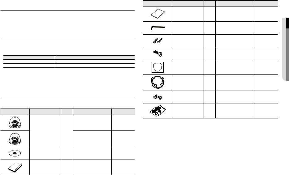
What’s Included
Please check if your camera and accessories are all included in the product package. (As for each sales country, accessories are not the same.)
Appearance |
Item Name |
Quantity |
Description |
Model Name |
|
|
|
|
SNV-L6013R |
|
Camera |
1 |
|
|
|
|
|
|
SNV-L6014RM |
|
Instruction book, |
1 |
|
SNV-L6013R/ |
|
Installer S/W CD |
|
SNV-L6014RM |
|
|
|
|
||
|
Quick Guide |
1 |
|
SNV-L6013R/ |
|
(Optional) |
|
SNV-L6014RM |
|
|
|
|
Appearance |
Item Name |
Quantity |
Description |
Model Name |
|
Warranty card |
1 |
|
SNV-L6013R/ |
|
(Optional) |
|
SNV-L6014RM |
|
|
|
|
||
|
L Wrench |
1 |
Used to remove/fix the dome cover |
SNV-L6013R/ |
|
SNV-L6014RM |
|||
|
|
|
|
|
|
M4 Tapping Screw |
2 |
Used for securing the camera to the |
SNV-L6013R/ |
|
wall or ceiling |
SNV-L6014RM |
||
|
|
|
||
|
Plastic Anchor |
2 |
For fixing a screw, Inserted in a hole |
SNV-L6013R/ |
|
(reinforced anchoring force) |
SNV-L6014RM |
||
|
|
|
||
|
Template |
1 |
Used when installing the camera |
SNV-L6013R/ |
|
SNV-L6014RM |
|||
|
|
|
|
|
|
Installation bracket |
1 |
Used when installing the camera on |
SNV-L6013R/ |
|
the wall or a gang box (single) |
SNV-L6014RM |
||
|
|
|
||
|
M4 screw for installation |
2 |
Used when fixing the camera on the |
SNV-L6013R/ |
|
bracket |
installation bracket |
SNV-L6014RM |
|
|
|
|||
|
RJ45 waterproof accessory |
1 |
Used for waterproofing the RJ45 |
SNV-L6013R |
|
connector cable |
|||
|
|
|
|
overview ●●
English _7
overview
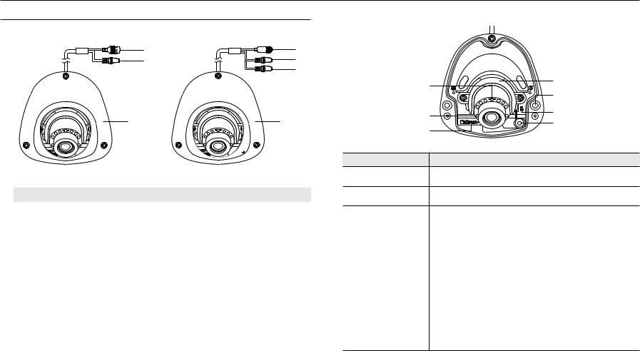
At a Glance
Appearance
a |
d |
b |
e |
|
b |
c |
c |
<SNV-L6013R> |
|
<SNV-L6014RM> |
|
|
|
|
|
Item |
|
|
Description |
a PoE Connector |
|
Connects to the network and supplies power through Ethernet cable. |
|
|
|
|
|
b Audio In Jack |
|
SNV-L6013R |
Used to connect to a microphone. (black) |
|
SNV-L6014RM |
Used to connect to a microphone. (pink) |
|
|
|
||
c Dome Cover |
|
Dome cover for the lens and unit protection. |
|
|
|
|
|
d cableM12 Female connector |
|
Connect to the M12 Male connector cable for power supply and network connections. |
|
e Audio Out Jack |
|
Used to connect to speakers. (green) |
|
MM`` Wipe out a dirty surface of the lens softly with a lens tissue or cloth to which you have applied ethanol.
Inside
|
g |
|
a |
|
|
b |
|
|
|
|
|
|
f |
RESET |
c |
|
|
||
|
|
d |
|
|
e |
|
|
|
|
|
|
Item |
|
Description |
|
a Lens Cover |
|
Used for protecting and fixing the lens. |
|
b Fixing Hole |
|
Hole used for securing the camera on a ceiling. |
|
|
Resets the camera settings to the default. Press and hold for about 5 seconds to reboot the |
|
system. |
c Reset Button |
J If you reset the camera, the network settings will be adjusted so that DHCP can be |
enabled. If there is no DHCP server in the network, you must run the IP Installer |
|
|
program to change the basic network settings such as IP address, Subnet mask, |
|
Gateway, etc., before you can connect to the network. |
d Microphone hole |
A microphone is embedded. |
` |
|
|
` It is applicable only to the SNV-L6014RM model. |
Micro SD Memory Card |
Compartment for the Micro SD memory card. |
e Compartment |
|
f IR LED |
These infrared LED’s are controlled by the illumination sensor. |
|
|
g Illumination Sensor |
Detects incoming light to control the IR LED. |
8_ overview
installation & connection
Installation
Precautions before installation
Ensure you read out the following instructions before installing the camera:
•• When installing on a ceiling, desired spot must be capable of supporting at least 5 times of the camera’s weight.
•• Stuck-in or peeled-off cables can cause damage to the product or a fire.
•• For safety purposes, keep anyone else away from the installation site. And put aside personal belongings from the site, just in case.
•• This camera (SNV-L6014RM) is compliance with the IP66 specifications and is a water proof product, however, no waterproofing will be provided with the jack if you don’t use the M12 connector and cables.
When you install this product, it is recommended to use an external cable that meets the M12 specification.
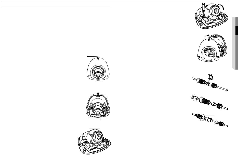
Disassembling
Using the L-wrench provided, loosen 3 screws by turning them counterclockwise and separate the dome cover.
`` Note that it is not necessary to loosen the screw completely.
6. After adjusting the angle, turn the screws clockwise to fix the lens angle. |
0~67° |
7. Close the dome cover and turn it clockwise using the L-wrench.
JJ`` If the cover is not fixed tightly, you may encounter a problem with waterproofing. (IP66)
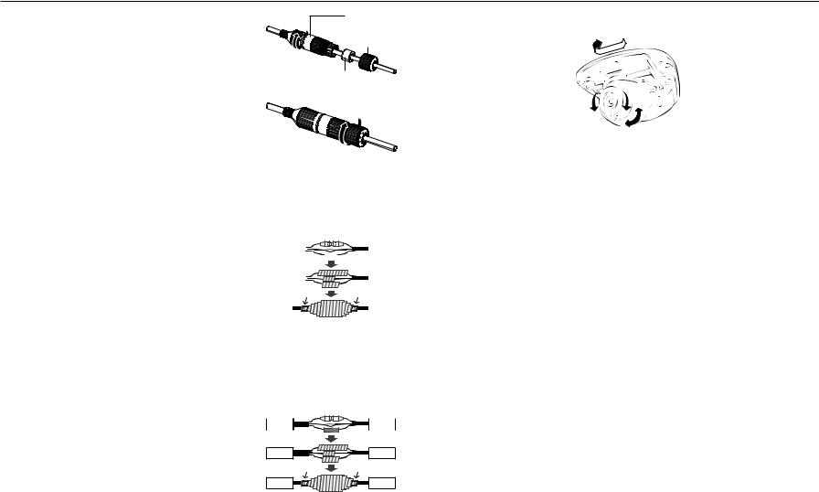
How to connect the RJ45 waterproof cable to a LAN cable (SNV-L6013R)
1. Insert it through the arrow direction.
Installing the camera on the ceiling
1.Select a location where you want to install the camera.
2.Prepare a hole for a screw on the wall where you are going to install the device, then insert the plastic drywall anchor that has been provided all the way into the hole.
3.Align the internal hole with the hole into which the plastic anchor has been inserted, and turn the tapping screw clockwise to fasten it.
MM`` Use the enclosed installation bracket when installing the product on the wall.
4.Turn the screws on both sides of the camera lens cover counterclockwise to loosen them.
JJ`` Forcingdefect. to tile the lens (hood) without loosening the screws may cause a product
5.Adjust the lens in a desired direction by referring to the “Adjusting the monitoring direction for the camera” section. (page 10)
RESET |
Fixing Hole
Lens cover
2.Connect the LAN connector (male) to the cable.
3.Connect the RJ45 modular jack (female) to the RJ45 connector (male).
JJ`` Please, keep each of the parts separated.
RJ45 connector (male)
RJ45 modular  jack (female)
stallatin ●● & ion onnec ction
English _9
installation & connection
4. Assemble by rotating the RJ45 modular jack (female) and the RJ45 |
RJ45 connector |
protection cover clockwise (Follow the arrow). |
protection cover |
|
Back cover |
|
Cable waterproof |
|
gasket |
5.Assemble by rotating RJ45 protection cover and back cover clockwise (Follow the arrow).
When the back cover is assembled, the cable waterproof gasket is tightly attached to the cable to make it waterproof.
JJ`` You must fully assemble it to rotate the back cover up to the end of the screw thread of the RJ45 connector.
Outdoor installation (SNV-L6013R)
When you install it outside of the building, please waterproof it with waterproof butyl rubber tape (can be purchased in stores) so that water does not leak from the gap of the cable connected to the outside.
1. Connect the power, Audio In, and LAN cables. |
|
|
|
|
|
|
|
|
|
|
|
|
|
|
|
Camera |
|
|
|
|
|
|
|
|
|
|
System |
||
2. Wrap the black cable jacket (Area A) and the cable connection area |
|
|
|
|
|
|
|
|
|
|
|
|
|
|
|
|
|
|
|
|
|
|
|
|
|
|
|
||
with waterproof (butyl rubber) tape so that more than half of the |
|
|
|
|
|
|
|
|
|
|
|
|
||
butyl rubber tape is overlapped. |
Camera |
|
|
|
|
|
|
|
|
|
|
System |
||
JJ`` |
|
|
|
|
|
|
|
|
|
|
|
|
||
|
|
|
|
|
|
|
|
|
|
|
|
|
||
If the cable jacket is not waterproofed properly, then it can directly cause |
|
A |
|
|
|
|
|
|
|
|
A |
|||
|
leakage. Make sure to protect the cable with a dense layer of taping. |
|
|
|
|
|
|
|
|
|
|
|
|
|
|
Camera |
|
|
|
|
|
|
|
|
|
|
System |
||
`` |
|
|
|
|
|
|
|
|
|
|
|
|
|
|
Waterproof butyl tape is made of butyl rubber that can be stretched to twice |
|
|
|
|
|
|
|
|
|
|
|
|
||
|
its normal length. |
|
|
|
|
|
|
|
|
|
|
|
|
|
Outdoor installation (SNV-L6014RM)
As water can leak from the gap of the externally connected cable if you install it outside a building without using an M12 connector and an M12 cable, you need to use waterproofing butyl rubber tape for waterproofing as shown below.
1.Connect the power, Audio I/O, and LAN cables.
2.Wrap the black cable jacket (Area A) and the cable connection area with waterproof (butyl rubber) tape so that more than half of the butyl rubber tape is overlapped.
JJ`` If the cable jacket is not waterproofed properly, then it can directly cause leakage. Make sure to protect the cable with a dense layer of taping.
`` Waterproof butyl tape is made of butyl rubber that can be stretched to twice its normal length.
Camera |
Camera
A
Camera
System |
System
A
System
Adjusting the monitoring direction for the camera
 Pan
Pan
Lens rotation 

Tilt
`` Adjusting the monitoring direction
You can adjust the camera direction only when the camera is fixed on the ceiling.
Where, rotating the camera unit to the left or right is called Pan, adjusting the tilt is called Tilt, and turning the lens on its axis is called Rotation.
-- The maximum PAN range is from -5˚ to +5˚. -- The angle of ROTATE is either -90˚ or +90˚. -- The total range of TILT is 67˚.
JJ `` Use of the camera at an angle that is out of the specifications may cause reflection by IR or blind image.
`` Methods of adjustment
1.After installing the camera, adjust the panning angle in consideration of the monitoring direction.
2.Set the horizontal angle so that the image is not reversed.
3.Adjust the tilt angle so that the camera faces toward the monitoring object.
10_ installation & connection
Inserting/Removing a Micro SD Memory Card
JJ`` Disconnect the power cable from the camera before inserting the Micro SD memory card.
`` Do not insert the Micro SD memory card while it’s upside down by force. Otherwise, it may damage the Micro SD memory card.
`` When it rains or the humidity is high, insertion or ejection of a Micro SD card is not recommended.
`` Disassembly of the product cover should be finished within 5 minutes, or there will be the risk of internal dew condensation.
Inserting a Micro SD Memory Card
Push the Micro SD memory card in the direction of the arrow shown in the diagram.
 RESET
RESET
Removing a Micro SD Memory Card
Gently press down on the exposed end of the memory card as shown in the diagram to eject the memory card from the slot.
 RESET
RESET
JJ`` Pressing too hard on the Micro SD memory card can cause the card to shoot out uncontrollably from the slot when released.
`` Before removing your Micro SD memory card, turn off the camera or go to <Storage>, turn the device off, and press the [Apply ( )] button. (Page 38)
`` If you turn off the camera or remove the Micro SD memory card that contains data from the product, the data may be lost or damaged.
Memory Card Information (Not Included)
What is a memory card?
The memory card is an external data storage device that has been developed to offer an entirely new way to record and share video, audio, and text data using digital devices.
Selecting a memory card that’s suitable for you
Your camera supports Micro SD/SDHC/SDXC memory cards.
You may, however, experience compatibility issues depending on the model and make of the memory card.
For your camera, we recommend you use a memory card from the following manufacturers: Micro SD/SDHC/SDXC Memory Card : Sandisk, Transcend
Memory cards of 4GB ~ 32GB is recommended for using with this camera.
Playback performance can be affected depending on the speed of memory card, so use the high-speed memory card.
Memory cards with a specification of Class 10 + UHS-1 or higher are recommended.
Memory Card Components
Contacts 


Micro SD/SDHC/SDXC
stallatin ●● & ion onnec ction
English _11
installation & connection
Connecting with other Device
PoE Device |
|
Making a connection using the M12-RJ45 conversion cable (SNV-L6014RM) |
|
Connect the M12 male connector for the conversion cable to the groove of the M12 Female connector for |
|
your camera. |
PoE Device |
MM`` M12-RJ45 cable is sold separately. |
<SNV-L6013R> |
<SNV-L6014RM> |
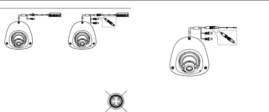
Connecting a connector cable (SNV-L6014RM)
Connect the M12 male connector into the hole of the M12 Female connector of the camera.
MM`` This camera uses Female, D-coded types. `` PoE (Power over Ethernet) is supported.
`` You are recommended to use a shielded network connector.
JJ`` |
Connect this camera to a shielded network cable (STP). |
RX- |
TX+ |
`` |
Please, use 4 poles, Male, D-coded type external cables that meet the M12 specification. |
|
|
`` |
Check whether the PoE device is properly connected to the ground. |
|
|
|
|
TX- |
RX+ |
Powering and networking (SNV-L6013R)
Connect a camera to a PoE equipment.
JJ`` Connect to a PoE (Power over Ethernet) enabled router’s PoE connector.
`` Use PoE (Power over Ethernet) that is compliant with the IEEE802.3af protocols.
Powering and networking (SNV-L6014RM)
Connect a camera to a PoE equipment or connect the M12-RJ45 connector for the conversion cable of your camera to a PoE equipment.
JJ`` A connection method may vary depending on the installation environment of a user. `` Connect to a PoE (Power over Ethernet) enabled router’s PoE connector.
`` Use PoE (Power over Ethernet) that is compliant with the IEEE802.3af protocols.
You can only use a Mode A PoE device that supplies power through data pin pair 1, 2, 3, 6.
`` Even if you use the M12-RJ45 conversion cable, you can only use a mode A type PoE equipment that supplies power to data pair pins 1, 2, 3, 6.
12_ installation & connection
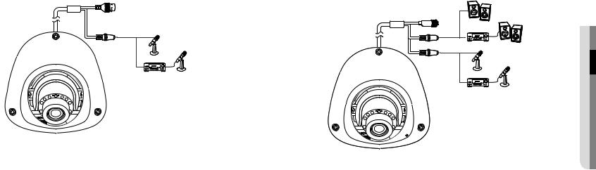
Connecting to Audio Input (SNV-L6013R)
Microphone |
Amp Microphone
1.Connect the AUDIO IN port of the camera with the microphone or LINE OUT port of the amplifier that the microphone is connected to.
2.Check the specifications for audio input.
•• Audio Codec
-- Audio In : G.711 PCM (Bit Rate: 64kbps / Sampling Frequency: 8kHz), G.726 ADPCM (Bit Rate: 16Kbps, 24Kbps, 32Kbps, 40Kbps / Sampling Frequency: 8kHz)
•• Full duplex Audio
•• Audio in : Mono signal line input (Max.2.4 Vpp)
|
ction |
Connecting to Audio Input/Output (SNV-L6014RM) |
onnec |
|
Speaker |
ion |
|
|
& |
Amp |
Speaker |
stallatin ●● |
|
||
Microphone |
|
|
Amp |
Microphone |
|
1.Connect the AUDIO IN port of the camera with the microphone or LINE OUT port of the amplifier that the microphone is connected to.
MM`` As a microphone is built in, you can use the built-in microphone instead of an external one.
2.Connect the AUDIO OUT port of the camera with the speaker or LINE IN port of the amplifier that the speaker is connected to.
3.Check the specifications for audio input.
•• Audio Codec
-- Audio In : G.711 PCM (Bit Rate: 64kbps / Sampling Frequency: 8kHz), G.726 ADPCM (Bit Rate: 16Kbps, 24Kbps, 32Kbps, 40Kbps / Sampling Frequency: 8kHz)
-- Audio Out : G.711 PCM (Bit Rate: 64kbps / Sampling Frequency: 8kHz)
•• Full duplex Audio
•• Audio in : Mono signal line input (Max.2.4 Vpp)
•• Audio out : Mono signal line output (Max.2.4 Vpp)
•• Line out impedance : 8Ω
English _13

network connection and setup
You can set up the network settings according to your network configurations.
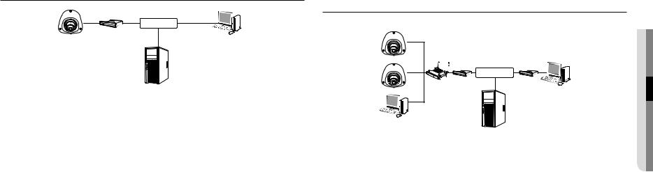
Connecting the Camera Directly to Local Area Networking
Connecting to the camera from a local PC in the LAN
1.Launch an Internet browser on the local PC.
2.Enter the IP address of the camera in the address bar of the browser.
Camera |
|
|
INTERNET |
Camera |
External Remote PC |
Local PC |
DDNS Server |
(Data Center, KOREA) |
<Local Network>
MM`` A remote PC in an external Internet out of the LAN network may not be able to connect to the camera installed in the intranet if the port-forwarding is not properly set or a firewall is set.
In this case, to resolve the problem, contact your network administrator.
`` In the IP installer, you can use the initial password, “4321” to set IP Address, Subnet Mask, Gateway, HTTP Port, VNP Port, IP type. After changing the network interface, for better security, access the web viewer and change the password.
`` By factory default, the IP address will be assigned from the DHCP server automatically. If there is no DHCP server available, the IP address will be set to 192.168.1.100.
To change the IP address, use the IP Installer.
For further details on IP Installer use, refer to “Static IP Setup”. (Page 16)
Connecting the Camera Directly to a DHCP Based DSL/Cable Modem
|
INTERNET |
|
DSL/Cable Modem |
Camera |
External Remote PC |
DDNS Server
(Data Center, KOREA)
1.Connect the user PC directly with the network camera.
2.Run the IP Installer and change the IP address of the camera so that you can use the web browser on your desktop to connect to the Internet.
3.Use the Internet browser to connect to the web viewer.
4.Move to [Setup] page.
5.Move to [Network] – [DDNS] and configure the DDNS settings.
6.Move to [Basic] – [IP & Port], and set the IP type to [DHCP].
7.Connect the camera, which was removed from your PC, directly to the modem.
8.Restart the camera.
MM`` |
For configuring the DDNS settings, refer to “DDNS”. (page 34) |
`` |
For registering the DDNS settings, refer to “Registering with DDNS”. (page 35) |
`` |
Refer to “IP & Port” for how to setup IP. (page 30) |
14_ network connection and setup
Connecting the Camera Directly to a PPPoE Modem
|
INTERNET |
|
PPPoE Modem |
Camera |
External Remote PC |
DDNS Server
(Data Center, KOREA)
1.Connect the user PC directly with the network camera.
2.Run the IP Installer and change the IP address of the camera so that you can use the web browser on your desktop to connect to the Internet.
3.Use the Internet browser to connect to the web viewer.
4.Move to [Setup] page.
5.Move to [Network] – [DDNS] and configure the DDNS settings.
6.Move to [Basic] – [IP & Port] Setup Page, set the IP type to [PPPoE], and enter the network service’s ID and password.
7.Connect the camera, which was removed from your PC, directly to the modem.
8.Restart the camera.
MM`` |
For configuring the DDNS settings, refer to “DDNS”. (page 34) |
`` |
For registering the DDNS settings, refer to “Registering with DDNS”. (page 35) |
`` |
Refer to “IP & Port” for how to setup IP. (page 30) |
Connecting the Camera to a Broadband Router with the PPPoE/Cable Modem
This is for a small network environment such as homes, SOHO and ordinary shops.
Camera |
|
|
|
|
|
|
|
INTERNET |
|
|
Broadband |
PPPoE or |
PPPoE or |
|
Camera |
Cable Modem |
Cable Modem |
External Remote PC |
|
Router |
|
|
||
|
|
|
DDNS Server |
|
Local PC |
|
|
(Data Center, KOREA) |
|
|
|
|
|
Configuring the network settings of the local PC connected to a Broadband Router
Configuring the network settings of the local PC connected to a Broadband Router, follow the instructions below.
•• Select : <Network> <Properties> <Local Area Connection> <General> <Properties> <Internet Protocol (TCP/IP)> <Properties> <Obtain an IP address automatically> or <Use the following IP address>.
•• Follow the instructions below if you select <Use the following IP address>:
ex1) If the address (LAN IP) of the Broadband Router is 192.168.1.1 IP address : 192.168.1.100
Subnet Mask : 255.255.255.0
Default Gateway : 192.168.1.1
ex2) If the address (LAN IP) of the Broadband Router is 192.168.0.1 IP address : 192.168.0.100
Subnet Mask : 255.255.255.0
Default Gateway : 192.168.0.1
ex3) If the address (LAN IP) of the Broadband Router is 192.168.xxx.1 IP address : 192.168.xxx.100
Subnet Mask : 255.255.255.0 Default Gateway : 192.168.xxx.1
MM`` For the address of the Broadband Router, refer to the product’s documentation.
`` For more information about port forwarding of the broadband router, refer to “Port Range Forward (Port Mapping) Setup”. (Page 18)
newor●●t onnek c ction and
English _15
network connection and setup
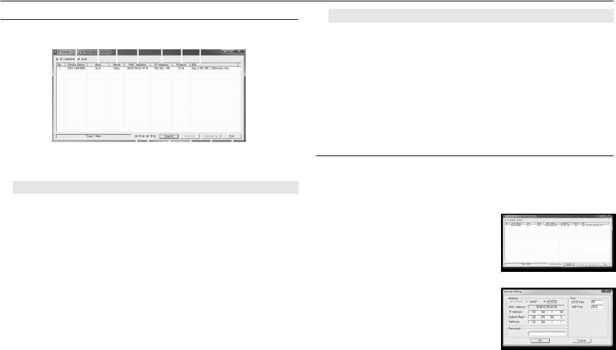
Buttons used in IP Installer
a b c d e f g
|
|
|
|
|
|
|
|
|
|
|
|
|
|
|
|
|
|
|
|
|
|
|
|
|
|
|
|
|
|
|
|
|
|
|
|
|
|
|
|
|
|
|
|
|
|
|
|
|
|
|
|
|
|
|
|
|
|
|
|
|
|
|
|
|
|
|
|
|
|
|
|
|
|
|
|
|
|
|
|
|
|
|
|
|
|
|
|
|
|
|
hi |
|
j k |
l m |
|||||||
|
|
|
|
|
|
|
|
|
|
|
|
|
|
|
|
|
Item |
|
|
|
|
|
|
|
Description |
||||||||
a Device Name |
|
Model name of the connected camera. |
|
|
|
|
||||||||||
|
Click the column to sort the list by model name. |
|
|
|
|
|||||||||||
|
|
|
|
However, search will be stopped if clicked during the search. |
||||||||||||
b Alias |
|
This function is not currently implemented. |
|
|
|
|
||||||||||
c Mode |
|
Displays either <Static>, <Dynamic> or <PPPoE> for the current network connection |
||||||||||||||
|
status. |
|
|
|
|
|||||||||||
d MAC(Ethernet) Address |
|
Ethernet address for the connected camera. |
|
|
|
|
||||||||||
|
Click the column to sort the list by Ethernet address. |
|||||||||||||||
|
|
|
|
However, search will be stopped if clicked during the search. |
||||||||||||
e IP Address |
|
IP address. |
|
|
|
|
||||||||||
|
Click the column to sort the list by IP address. |
|
|
|
|
|||||||||||
|
|
|
|
However, search will be stopped if clicked during the search. |
||||||||||||
f Protocol |
|
Network setting for the camera. |
|
|
|
|
||||||||||
|
The factory default is “IPv4”. |
|
|
|
|
|||||||||||
|
|
|
|
Cameras with the IPv6 setting will be displayed “IPv6”. |
||||||||||||
g URL |
|
DDNS URL address enabling access from the external Internet. |
||||||||||||||
|
However, this will be replaced with the <IP Address> of the camera if DDNS registration |
|||||||||||||||
|
|
|
|
has failed. |
|
|
|
|
||||||||
h IPv4 |
|
Scans for cameras with the IPv4 setting. |
|
|
|
|
||||||||||
Item |
Description |
i IPv6 |
Scans for cameras with the IPv6 setting. |
Activated in an IPv6 compliant environment only. |
|
j Search |
Scans for cameras that are currently connected to the network. |
However, this button will be grayed out if neither IPv4 nor IPv6 is checked. |
|
k Auto Set |
The IP Installer automatically configures the network settings. |
l Manual Set |
You should configure the network settings manually. |
m Exit |
Exits the IP Installer program. |
MM`` For the IP installer, use only the installer version provided in the installation CD or use the latest one if available. You can download the latest version from the Samsung web site.
Static IP Setup
Manual Network Setup
Run <IP Installer_v2.XX.exe> to display the camera search list.
At the initial startup, both [Auto Set] and [Manual Set] will be grayed out.
MM`` For cameras found with the IPv6 setting, these buttons will be grayed out as the cameras do not support this function.
1.Select a camera in the search list.
Check the MAC address of the camera on the camera’s label. Both the [Auto Set] and [Manual Set] buttons will be activated.
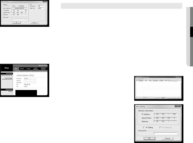
2.Click [Manual Set].
The Manual Setting dialog appears.
<IP Address>, <Subnet Mask>, <Gateway>, <HTTP Port>, and <VNP Port> of the camera are displayed in the preset values.
3.In the <Address> pane, provide the necessary information.
•• MAC (Ethernet) Address : The MAC address imprinted on the camera label is automatically displayed and requires no user setting.
MM`` IP related parameters can be set only when DHCP is not checked.
16_ network connection and setup
If not using a Broadband Router
For setting <IP Address>, <Subnet Mask>, and <Gateway>, contact your network administrator.
4.In the <Port> pane, provide necessary information.
•• HTTP Port : Used to access the camera using the Internet browser, defaulted to 80.
•• VNP Port : Used to control the video signal transfer, defaulted to 4520.
5.Enter the password.
Enter the password of “admin” account, which was used to access the camera.
JJ`` For the security purposes, you are recommended to use a combination of numbers, alphabets uppercase and lowercase and special characters for your password.
`` If you want to change the password, refer to “Administrator password change” of the user setup. (page 29)
6.Click [OK].
Manual network setup will be completed.
If using a Broadband Router
•• IP Address : Enter an address falling in the IP range provided by the Broadband Router.
ex) 192.168.1.2~254, 192.168.0.2~254, 192.168.XXX.2~254
•• Subnet Mask : The <Subnet Mask> of the Broadband Router will be the <Subnet Mask> of the camera.
•• Gateway : The <Local IP Address> of the Broadband Router will be the <Gateway> of the camera.
MM`` The settings may differ depending on the connected Broadband Router model.
For more information, refer to the user manual of the applicable router.
`` For more information about port forwarding of the broadband router, refer to “Port Range Forward (Port Mapping) Setup”. (Page 18)
If the Broadband Router has more than one camera connected
Configure the IP related settings and the Port related settings distinctly with each other. ex)
|
Category |
Camera #1 |
Camera #2 |
|
IP related settings |
|
IP Address |
192.168.1.100 |
192.168.1.101 |
|
Subnet Mask |
255.255.255.0 |
255.255.255.0 |
|
|
|
Gateway |
192.168.1.1 |
192.168.1.1 |
Port related settings |
|
HTTP Port |
8080 |
8081 |
|
VNP Port |
4520 |
4521 |
|
MM`` If the <HTTP Port> is set other than 80, you must provide the <Port> number in the address bar of the Internet browser before you can access the camera.
ex) http://IP address : HTTP Port http://192.168.1.100:8080
Auto Network Setup
Run <IP Installer_v2.XX.exe> to display the camera search list.
At the initial startup, both [Auto Set] and [Manual Set] will be grayed out.
MM`` For cameras found with the IPv6 setting, these buttons will be grayed out as the cameras do not support this function.
1.Select a camera in the search list.
Check the MAC address of the camera on the camera’s label. Both the [Auto Set] and [Manual Set] buttons will be activated.
2.Click [Auto Set].
The Auto Setting dialog appears.
The <IP Address>, <Subnet Mask>, and <Gateway> will be set automatically.
3.Enter the password.
Enter the password of “admin” account, which was used to access the camera.
JJ`` For the security purposes, you are recommended to use a combination of numbers, alphabets uppercase and lowercase and special characters for your password.
`` If you want to change the password, refer to “Administrator password change” of the user setup. (page 29)
4.Click [OK].
Auto network setup will be completed.
newor●●t onnek c ction and
English _17
network connection and setup
Dynamic IP Setup
Dynamic IP Environment Setup
•• Example of the Dynamic IP environment
-- If a Broadband Router, with cameras connected, is assigned an IP address by the DHCP server -- If connecting the camera directly to modem using the DHCP protocols
-- If IPs are assigned by the internal DHCP server via the LAN
Checking the Dynamic IP
1.Run the IP Installer on the user’s local computer.
Cameras allocated with <Dynamic IP> address are shown in the list.
2.Select a camera from the search result.
3.Click the [Manual Set] button and check the camera’s <Dynamic IP> address.
If you uncheck <DHCP>, you can change IP to <Static>.
Port Range Forward (Port Mapping) Setup
If you have installed a Broadband Router with a camera connected, you must set the port range forwarding on the Broadband Router so that a remote PC can access the camera in it.
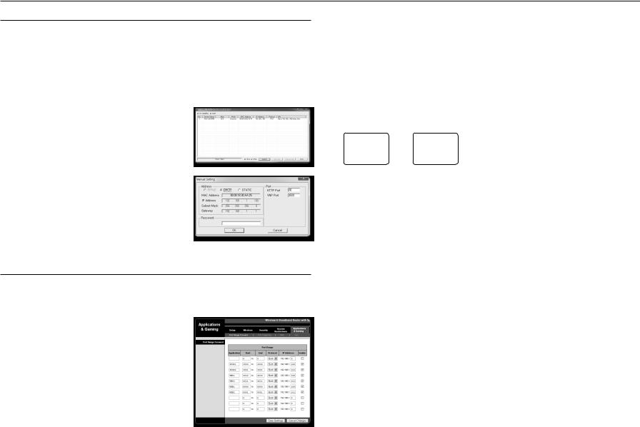
Manual Port Range Forwarding
1.From the Setup menu of the Broadband Router, select <Applications & Gaming> - <Port Range Forward>.
For setting the port range forward for a third-party Broadband Router, refer to the user guide of that Broadband Router.
2.Select <TCP> and <UDP Port> for each connected camera to the Broadband Router.
Each port number for the Broadband Router should match that specified in <Setup> - <Basic> - <IP & Port> from the camera’s web viewer menu.
3.When done, click [Save Settings]. Your settings will be saved.
MM`` Above sample instructions are based on the CISCO’s Broadband Router.
`` The settings may differ depending on the connected Broadband Router model. For more information, refer to the user manual of the applicable router.
Setting up Port Range Forward for several network cameras
•• You can set a rule of Port Forwarding on the Broadband Router device through its configuration web page.
•• A user can change each port using the camera setting screen. When Camera1 and Camera2 are connected to a router :
User |
|
Internet |
|
|
|
|||
|
|
|
|
|
|
|
|
|
|
|
|
|
|
|
|
Camera1 (192.168.1.100) |
|
|
|
Broadband Router |
|
|
|
|
||
|
|
|
|
HTTP port |
8080 |
|||
Start |
|
End |
|
Protocol |
IP Address |
Device port |
4520 |
|
3000 |
|
3000 |
|
TCP/UDP |
192.168.1.100 |
|||
|
|
|
RTSP port |
3000 |
||||
3001 |
|
3001 |
|
TCP/UDP |
192.168.1.101 |
|
||
|
|
|
|
|
||||
4520 |
|
4520 |
|
TCP/UDP |
192.168.1.100 |
|
|
|
|
|
|
|
|
|
|
Camera2 (192.168.1.101) |
|
4521 |
|
4521 |
|
TCP/UDP |
192.168.1.101 |
|
||
8080 |
|
8080 |
|
TCP/UDP |
192.168.1.100 |
|
HTTP port |
8081 |
|
|
Device port |
4521 |
|||||
8081 |
|
8081 |
|
TCP/UDP |
192.168.1.101 |
|||
|
|
|
RTSP port |
3001 |
||||
|
|
|
|
|
|
|
||
MM`` Port forwarding can be done without additional router setup if the router supports the UPnP (Universal Plug and Play) function. After connecting the network camera, set <Quick connect> of <Samsung DDNS> to <On> in the “Setup Network DDNS” menu.
18_ network connection and setup
 Loading...