


ENGLISH
Document No. CSD-SMESAR7
Revision 03
Copyright SAMSUNG MEDISON Co., LTD.
Safety Requirements
Classifications:
-Type of protection against electrical shock: Class I
-Degree of protection against electrical shock (Patient connection):Type BF equipment
-Degree of protection against harmful ingress of water: Ordinary equipment
-Degree of safety of application in the presence of a flammable anesthetic material with air or with oxygen or nitrous oxide: Equipment not suitable for use in the presence of a flammable anesthetic mixture with air or with oxygen or nitrous oxide.
-Mode of operation: Continuous operation
Electromechanical safety standards met:
-IEC/EN 60601-1 Medical Electrical Equipment, Part 1General Requirements for Safety.
-IEC/EN 60601-1-1 Safety requirements for medical electrical systems.
-IEC/EN 60601-1-2 Electromagnetic compatibility -Requirements and tests.
-IEC/EN 60601-2-37 Particular requirements for the safety of ultrasonic medical diagnostic and monitoring equipment.
-IEC 61157 Declaration of acoustic output parameters.
-ISO 10993-1 Biological evaluation of medical devices.
-UL 60601-1 Medical Electrical Equipment, Part 1 General Requirements for Safety.
-CSA 22.2, 601.1 Medical Electrical Equipment, Part 1 General Requirements for Safety.

Declarations:
This is CSA symbol for Canada and United States of America
This is manufacturer’s declaration of product compliance
0123 with applicable EEC directive(s) and the European notified body.
This is manufacturer’s declaration of product compliance with applicable EEC directive(s).
This is GMP symbol for Good Manufacturing Practice of
Korea quality system regulation.
Certificate of Excellent Service Quality is to certify that the above company has served customers with excellent services by the Ministry of Knowledge Economy Republic of Korea.

READ THIS FIRST
How to Use Your Manual
This manual addresses the reader who is familiar with ultrasound techniques. Only medical doctors or persons supervised by medical doctors should use this system. Sonography training and clinical procedures are not included here. This manual is not intended to be used as training material for the principles of ultrasound, anatomy, scanning techniques, or applications. You should be familiar with all of these areas before attempting to use this manual or your ultrasound system.
This manual does not include diagnosis results or opinions also, check the measurement reference for each application’s result measurement before the diagnosis.
It is useless to make constant or complex adjustments to the equipment controls. The system has been preset at the factory to produce an optimum image in the majority of patients. User adjustments are not usually required. If the user wishes to change image settings, the variables may be set as desired. Optimal images are obtained with little difficulty.
We are not responsible for errors that occur when the system is run on a user’s PC. Non-Medison product names may be trademarks of their respective owners.
Please keep this user guide close to the product as a reference when using the system.
For safe use of this product, you should read ‘Chapter1. Safety’ and ‘Chapter8. Maintenance’ in this manual, prior to starting to use this system.
DANGER˙ ˙ ˙ ˙ ˙ ˙
Describes precautions necessary to prevent user hazards of great urgency. Ignoring a DANGER warning will risk life-threatening injury.
W˙ A˙ RNIN˙ ˙˙˙ G˙
Used to indicate the presence of a hazard that can cause serious personal injury, or substantial property damage.
CAUTION˙ ˙ ˙ ˙˙ ˙ ˙
Indicates the presence of a hazard that can cause equipment damage.
NOTE˙ ˙ ˙ ˙
A piece of information useful for installing, operating and maintaining a system. Not related to any hazard.

Contents
Chapter1. |
General Information |
|
|
1.1 |
Overview .................................................................................................... |
1-1 |
|
1.2 |
Features and Advantages of SonoAceR7 ............................................... |
1-2 |
|
1.3 |
Product Configuration................................................................................. |
1-3 |
|
|
1.3.1 |
Console............................................................................................. |
1-3 |
|
1.3.2 |
LCD Monitor ..................................................................................... |
1-4 |
|
1.3.3 |
Control Panel.................................................................................... |
1-5 |
|
1.3.4 |
Probes............................................................................................... |
1-5 |
1.4 |
Specifications............................................................................................... |
1-6 |
|
Chapter2. |
Safety |
|
|
2.1 |
Overview .................................................................................................... |
2-1 |
|
2.2 |
Safety – Related Information ..................................................................... |
2-2 |
|
|
2.2.1 |
Safety Symbols ................................................................................ |
2-2 |
|
2.2.2 |
LABEL............................................................................................... |
2-4 |
2.3 |
Safety Symbols ........................................................................................... |
2-5 |
|
|
2.3.1 |
Prevention Electric Shock............................................................... |
2-5 |
|
2.3.2 |
ESD ................................................................................................... |
2-6 |
|
2.3.3 |
EMI .................................................................................................... |
2-6 |
|
2.3.4 |
EMC .................................................................................................. |
2-7 |
2.4 |
Mechanical Safety..................................................................................... |
2-12 |
|
|
2.4.1 |
Moving Equipment......................................................................... |
2-12 |
|
2.4.2 |
Moving Equipment......................................................................... |
2-13 |
2.5 |
Biological Safety........................................................................................ |
2-14 |
|
|
2.5.1 |
Biological Safety............................................................................. |
2-14 |
2.6 |
Environmental Protection......................................................................... |
2-25 |
|
Contents

Contents
Chapter3. |
Installing the Product |
|
|
3.1 |
Overview |
.................................................................................................... |
3-1 |
3.2 |
Transportation ............................................................................................. |
3-3 |
|
|
3.2.1 |
Precautions for Transportation................................................ |
3-3 |
|
3.2.2 |
Temperature and Humidity ..................................................... |
3-3 |
3.3 |
Unpacking |
.................................................................................................... |
3-4 |
|
3.3.1 |
Unpacking the Box................................................................... |
3-4 |
|
3.3.2 |
Checking Package contents ................................................... |
3-5 |
3.4 |
Condition of Installation .............................................................................. |
3-6 |
|
|
3.4.1 |
Precautions for Installation ...................................................... |
3-6 |
|
3.4.2 |
Installation Place....................................................................... |
3-6 |
3.5 |
Installation Procedure................................................................................. |
3-7 |
|
|
3.5.1 |
Installation Safety ..................................................................... |
3-7 |
|
3.5.2 |
Connecting the Power Cord.................................................... |
3-8 |
|
3.5.3 |
Connecting the Network Cable............................................... |
3-9 |
|
3.5.4 |
Connecting the Probe.............................................................. |
3-9 |
3.6 |
Starting the Product .................................................................................. |
3-10 |
|
3.7 |
Shutting down the Product....................................................................... |
3-11 |
|
|
3.7.1 |
Power S/W .............................................................................. |
3-11 |
|
3.7.2 |
Power Breaker........................................................................ |
3-11 |
3.8 |
Connecting the Peripherals...................................................................... |
3-12 |
|
|
3.8.1 |
Internal Peripherals ................................................................ |
3-12 |
|
3.8.2 |
External Peripherals............................................................... |
3-12 |
3.9 |
System Setting .......................................................................................... |
3-14 |
|
|
3.9.1 |
System-General ..................................................................... |
3-14 |
|
3.9.2 |
System-Display....................................................................... |
3-17 |
3.10 |
Peripherals Setting.................................................................................... |
3-20 |
|
|
3.10.1 |
Peripherals .............................................................................. |
3-20 |
|
3.10.2 |
Foot Switch ............................................................................. |
3-20 |
|
3.10.3 |
Set / Exit key Setup................................................................ |
3-20 |
|
3.10.4 |
User key Setup ....................................................................... |
3-20 |
|
3.10.5 |
Print Setup............................................................................... |
3-21 |
3.11 |
System Information................................................................................... |
3-22 |
|
3.12 |
Setting DICOM ( Optional ) ...................................................................... |
3-23 |
|
|
3.12.1 |
DICOM Configuration ............................................................ |
3-23 |
|
3.12.2 |
DICOM Send Format............................................................. |
3-24 |
|
3.12.3 |
DICOM Compression ............................................................ |
3-24 |
|
3.12.4 |
Display compensation............................................................ |
3-24 |
Contents

|
3.12.5 |
Add DICOM Service .............................................................. |
3-25 |
|
3.12.6DICOM Server Information ........................................................... |
3-26 |
|
|
3.12.7 |
Print Server Information......................................................... |
3-27 |
|
3.12.8Worklist Information....................................................................... |
3-29 |
|
|
3.12.9PPS Information............................................................................. |
3-30 |
|
|
3.12.10 |
SC Information........................................................................ |
3-30 |
|
3.12.11 |
Storage SR Information......................................................... |
3-31 |
|
3.12.12 |
Add DICOM Service .............................................................. |
3-31 |
|
3.12.13 |
DICOM Service Delete .......................................................... |
3-31 |
|
3.12.14 |
DICOM Server Test ............................................................... |
3-31 |
|
3.12.15 |
DICOM Management ............................................................ |
3-31 |
|
3.12.16 |
DICOM Log............................................................................. |
3-33 |
|
3.12.17 |
Utility setting ............................................................................ |
3-34 |
3.13 |
Option setting............................................................................................. |
3-37 |
|
|
3.13.1 |
Option ...................................................................................... |
3-37 |
|
3.13.2 |
Auto Calc................................................................................. |
3-38 |
3.14 |
Measurement Setup ................................................................................. |
3-39 |
|
|
3.14.1 |
General setting ....................................................................... |
3-39 |
|
3.14.2 |
Packages................................................................................. |
3-41 |
|
3.14.3 |
Report ...................................................................................... |
3-45 |
|
3.14.4 |
Obstetrics Measurement Setup............................................ |
3-48 |
|
3.14.5Cardiac Measurement Setup ....................................................... |
3-54 |
|
|
3.14.6Vascular Measurement Setup...................................................... |
3-55 |
|
|
3.14.7Urology Measurement Setup ....................................................... |
3-56 |
|
|
3.14.8Fetal Echo Measurement Setup .................................................. |
3-57 |
|
Contents

Contents
Chpater4. |
Checking the Product |
|
|
4.1 |
Overview |
.................................................................................................... |
4-1 |
4.2 |
Starting the Product .................................................................................... |
4-2 |
|
4.3 |
Monitor |
.................................................................................................... |
4-3 |
|
4.3.1 |
Monitor Display......................................................................... |
4-3 |
4.4 |
Control Panel............................................................................................... |
4-5 |
|
|
4.4.1 |
Detail Control Panel ................................................................. |
4-5 |
|
4.4.2 |
Soft Menu................................................................................. |
4-7 |
|
4.4.3 |
Keyboards ................................................................................ |
4-7 |
|
4.4.4 |
Adjust of Control Panel ............................................................ |
4-8 |
4.5 |
Checking the Performance ........................................................................ |
4-9 |
|
|
4.5.1 |
Basic Check............................................................................. |
4-9 |
|
4.5.2 |
Detail Check .......................................................................... |
4-10 |
Contents

Contents
Chapter5. |
Product Structure |
|
5.1 |
Overview .................................................................................................... |
5-1 |
5.2 |
System Block Diagram............................................................................... |
5-3 |
5.3 |
Basic Structure of SonoAce R7................................................................. |
5-4 |
5.4 |
PSA .................................................................................................... |
5-6 |
5.5 |
Beamformer Part......................................................................................... |
5-8 |
5.6 |
CW Part .................................................................................................. |
5-11 |
5.7 |
Back End Part ......................................................................................... |
5-15 |
5.8 |
PCI Part .................................................................................................. |
5-19 |
5.9 |
Motor Control Part..................................................................................... |
5-20 |
5.12 |
PC Mother Board ...................................................................................... |
5-21 |
5.13 |
Software DSC............................................................................................ |
5-22 |
5.16 |
Control Panel............................................................................................. |
5-23 |
Contents
Contents
Chapter6. |
Basic Maintenance |
|
|
6.1 |
Overview |
.................................................................................................... |
6-1 |
6.2 |
System Information..................................................................................... |
6-2 |
|
6.3 |
Windows Mode............................................................................................ |
6-3 |
|
|
6.3.1 |
Entering Windows Mode ......................................................... |
6-3 |
6.4 |
Upgrade |
. ............................................................................................... |
6-4 |
|
6.4.1 |
Software Upgrade .................................................................... |
6-4 |
|
6.4.2 |
Hardware Upgrade................................................................... |
6-4 |
6.5 |
Admin mode ................................................................................................ |
6-5 |
|
|
6.5.1 |
Entering Admin Mode .............................................................. |
6-5 |
|
6.5.2 |
Admin Mode Functions............................................................ |
6-6 |
6.6 |
Adding and Deleting Options..................................................................... |
6-9 |
|
|
6.6.1 |
Option type................................................................................ |
6-9 |
|
6.6.2 |
Registering Option.................................................................. |
6-10 |
|
6.6.3 |
Option Delte ............................................................................ |
6-12 |
Contents

Contents
Chapter7. |
Troubleshooting |
|
|
7.1 |
Overview |
.................................................................................................... |
7-1 |
7.2 |
Power |
.................................................................................................... |
7-2 |
|
7.2.1 |
Power Failure............................................................................ |
7-2 |
|
7.2.2 |
Power cannot turned off .......................................................... |
7-2 |
|
7.2.3 |
Power is automatically turned off............................................ |
7-2 |
7.3 |
Monitor |
.................................................................................................... |
7-3 |
|
7.3.1 |
Blank Screen............................................................................. |
7-3 |
|
7.3.2 |
Screen Color Abnormal ........................................................... |
7-3 |
7.4 |
Error Messages........................................................................................... |
7-4 |
|
|
7.4.1 |
System hangs after an error during booting.......................... |
7-4 |
|
7.4.2 |
System works even if error occurred...................................... |
7-4 |
7.5 |
Image |
.................................................................................................. |
7-5 |
|
7.5.1 |
No BW Mode Image Echo ...................................................... |
7-5 |
|
7.5.2 |
No BW Mode Image Format................................................... |
7-5 |
|
7.5.3 |
Noise Link Rain over the BW Mode Image (Noise) ............. |
7-5 |
|
7.5.4 |
PW & CW & Color Doppler, M Mode Trouble ...................... |
7-5 |
Contents

Contents
Chapter8. |
Disassembly and Reassembly |
|
|
8.1 |
Overview |
.................................................................................................... |
8-1 |
8.2 |
Body Cover Disassembly and Reassembly ............................................ |
8-3 |
|
|
8.2.1 |
Preparations.............................................................................. |
8-3 |
|
8.2.2 |
Body Front Cover ..................................................................... |
8-3 |
|
8.2.3 |
Body Back Cover...................................................................... |
8-3 |
|
8.2.4 |
Cover Body Side Right & Left ................................................. |
8-4 |
|
8.2.5 |
Handle AY................................................................................. |
8-5 |
8.3 |
LCD & ARM & SPEAKER Disassembly and Reassembly.................... |
8-6 |
|
|
8.3.1 |
Preparations.............................................................................. |
8-6 |
|
8.3.2 |
LCD............................................................................................ |
8-6 |
|
8.3.3 |
SPEAKER................................................................................. |
8-7 |
|
8.3.4 |
ARM........................................................................................... |
8-9 |
8.4 |
Ultrasound System PCB Part Disassembly and Reassembly ............ |
8-11 |
|
|
8.4.1 |
Preparations............................................................................ |
8-11 |
|
8.4.2 |
PSA ASSY .............................................................................. |
8-11 |
|
8.4.3 |
CW Board, MAIN Board ........................................................ |
8-12 |
8.5 |
PC Part Disassembly and Reassembly ................................................. |
8-13 |
|
|
8.5.1 |
Preparations............................................................................ |
8-13 |
|
8.5.2 |
HDD & ODD............................................................................ |
8-13 |
|
8.5.3 |
Rear Board.............................................................................. |
8-14 |
|
8.5.4 |
POWER................................................................................... |
8-15 |
8.6 |
User Interface Part Disassembly and Reassembly .............................. |
8-16 |
|
|
8.6.1 |
Preparations............................................................................ |
8-16 |
|
8.6.2 |
Control Panel .......................................................................... |
8-16 |
|
8.6.3 |
Control Panel Board............................................................... |
8-17 |
|
8.6.4 |
Track Ball................................................................................. |
8-18 |
|
8.6.5 |
Alpha-Numeric Keyboard...................................................... |
8-19 |
|
8.6.6 |
LCDIF CON Board................................................................. |
8-20 |
Contents

Contents
Chapter9. |
Probe |
|
|
9.1 |
Overview |
.................................................................................................... |
9-1 |
9.2 |
Probe List |
.................................................................................................... |
9-2 |
|
9.2.1 |
Probe Application and Preset ................................................. |
9-2 |
|
9.2.2 |
Function List.............................................................................. |
9-3 |
9.3 |
Thermal Index (TI Table).......................................................................... |
9-5 |
|
9.4 |
Ultrasound Transmission Gel .................................................................... |
9-6 |
|
9.5 |
Sheaths |
.................................................................................................... |
9-7 |
9.6 |
Probe Precautions ...................................................................................... |
9-8 |
|
|
9.6.1 |
Use and Infection Control of the Probe.................................. |
9-8 |
|
9.6.2 |
Electric Shocks ......................................................................... |
9-9 |
9.7 |
Cleaning and Disinfecting the Probe ...................................................... |
9-10 |
|
9.7.1Information of Detergent, Disinfectant and Ultrasound Gel9-10
|
9.7.2 |
Cleaning .................................................................................. |
9-16 |
Chapter10. |
User Maintenance |
|
|
10.1 |
Overview |
.................................................................................................. |
10-1 |
10.2 |
System Maintenance................................................................................ |
10-2 |
|
|
10.2.1 |
Installation Maintenance........................................................ |
10-2 |
|
10.2.2 |
Cleaning and Disinfections.................................................... |
10-2 |
|
10.2.3 |
Fuse Replacement................................................................. |
10-3 |
|
10.2.4 |
Administration of Air Filter.................................................... |
10-4 |
|
10.2.4 |
Accuracy Check.................................................................... |
10-5 |
10.3 |
Administration of Information ................................................................... |
10-6 |
|
|
10.3.1 |
User Setting Back-up............................................................. |
10-6 |
|
10.3.2 |
Patient Information Restore................................................ |
10-6 |
|
10.3.3 |
Software .................................................................................. |
10-6 |
Chapter11. |
Service Part List |
|
|
11.1 |
Overview |
.................................................................................................. |
11-1 |
11.2 |
Body Cover ................................................................................................ |
11-2 |
|
11.3 |
Ultrasound System Part ......................................................................... |
11-4 |
|
11.4 |
LCD & HINGE Part ................................................................................... |
11-5 |
|
11.5 |
User Interface Part.................................................................................... |
11-6 |
|
11.6 |
PC & Power Part....................................................................................... |
11-8 |
|
11.7 |
ETC Part |
.................................................................................................. |
11-9 |
11.8 |
Options |
............................................................................................... |
11-12 |
11.9 |
Probes |
............................................................................................... |
11-13 |
Contents

Chapter 1. General Information
1.1Overview
Chapter 1 contains the information necessary to plan the Troubleshooting of SonoAceR7.
The SonoAceR7 is a high-resolution color ultrasound scanner with high penetration and a variety of measurement functions.
Contents
1.1 |
Overview |
...................................................................................................... |
1-1 |
1.2 |
Features and ................................................Advantages of SonoAceR7 |
1-2 |
|
1.3 |
Product Configuration................................................................................. |
1-3 |
|
|
1.3.1 ..................................................................................... |
Console |
1-3 |
|
1.3.2 .............................................................................. |
LCD Monitor |
1-4 |
|
1.3.3 ............................................................................ |
Control Panel |
1-5 |
|
1.3.4 ....................................................................................... |
Probes |
1-5 |
1.4 |
Specifications............................................................................................... |
1-6 |
|
Chapter 1. General Information 1-1

1.2Features and Advantages of SonoAceR7
High-end Digital Beam forming : The SonoAceR7 utilizes the newly developed Digital Beam forming technology.
A variety of applications : The SonoAceR7 is optimized for use in a variety of ultrasound departments, cardiac, vascular, abdomen, Obstetrics, Urology, Gynecology.
Various diagnostic Modes : 2D Mode, M Mode, Color Doppler Mode, Power Doppler Mode, PW Spectral Doppler Mode, etc.
Measurement and Report Functions : Besides the basic distance, area, circumference and volume measurement functions, the SonoAceR7 also provides application-specific measurement functions. The report function collates measurement data.
Review of Scanned Images : The SonoAceR7 displays Cine images of 7084 frames and loop images of 8192 lines.
SonoView TM : This is a total ultrasound image management system, which allows a user to archive, view and exchange documents.
Digital Imaging and Communication in Medicine (DICOM) Function : This is used to archive, transmit and print DICOM images through a network.
Peripheral/Accessory Connection : A variety of peripheral devices including VCRs and printers can be easily connected to the SonoAceR7.
Chapter 1. General Information 1-2
1.3Product Configuration
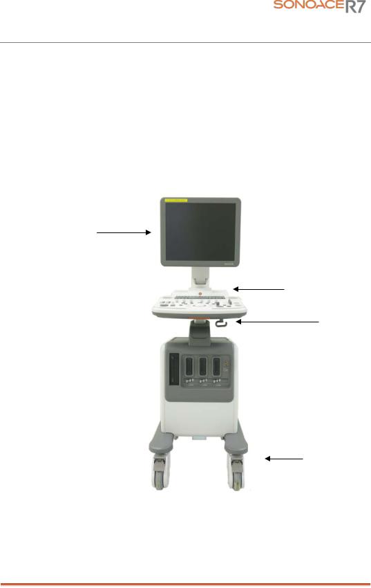
This Product consists of the monitor, the control panel, the console and, the probes.
1.3.1Console
The console consists of two parts – the inner unit and the outer unit.
The interior of the console mainly contains devices that produce ultrasound images.
The outside of the console consists of various connection ports, probe holder, storage space, wheel and handles.
LCD Monitor
Handle
Probe holder
Wheel
[Figure 1-1] Console of SonoAce R7
Chapter 1. General Information 1-3
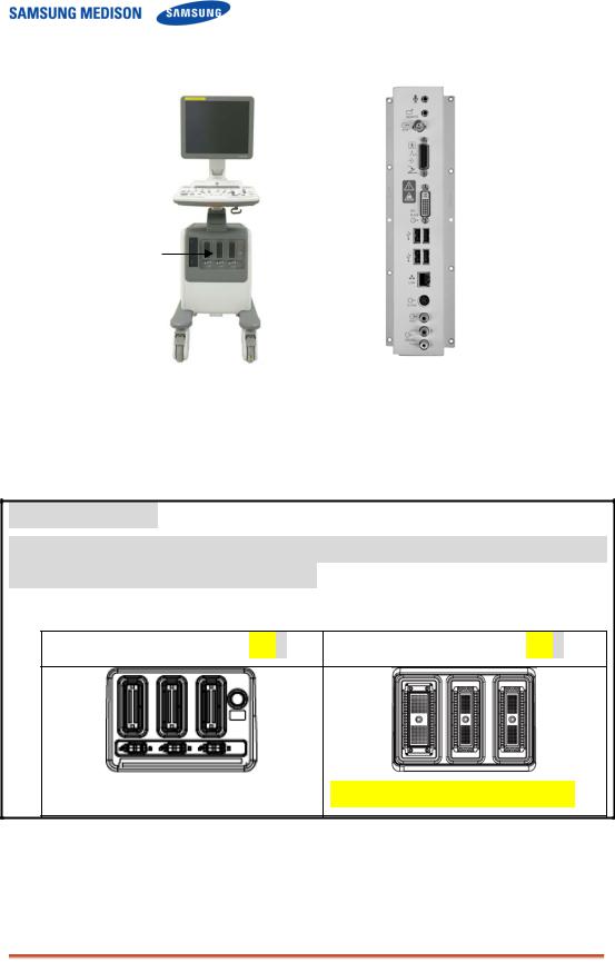
Probe Connector
[Figure 1-2] Front and Back of SonoAce R7
Type of Probe port
Mini DLP type of probe is used for SonoAce R7 v2.00.00. In lower version of product, the shape of the probe port can be different.
<v2.xx.xx: Mini DLP Type |
PSA> |
<v1.xx.xx :156 Pin Type |
PSA> |
||||
|
|
|
|
|
|
|
|
|
|
|
|
|
|
|
|
256 Pin is necessary for 3D probe.
Chapter 1. General Information 1-4
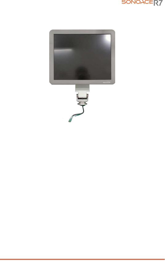
1.3.2LCD Monitor
The monitor of this system is a color VGA monitor, which displays ultrasound images and additional information. Monitor arm can control to be tilted to the optimal viewing angle.
[Figure 1-3] LCD Monitor
Chapter 1. General Information 1-5

1.3.3Control Panel
The control panel can be used for controlling the system.
Alpha-Numeric
Button
Dial Button
Track Ball
Slide Volume
[Figure 1-4] Control Panel
1.3.4Probe
Probes are devices that generate ultrasound waves and process reflected wave data for the purpose of image formation.
NOT˙ ˙ ˙E˙
For more information, refer to ‘Chapter 9. Probes’.
Chapter 1. General Information 1-6
1.4 Specifications
|
|
Height: 1340mm (with handle) |
|
Physical Dimensions |
|
Width: 450mm |
|
|
Depth: 700mm |
||
|
|
||
|
|
Weight: More than 61kg (With monitor) |
|
|
|
|
|
|
|
2D imaging mode |
|
|
|
M imaging mode |
|
|
|
Color Doppler Imaging (CDI) mode |
|
|
|
Power Doppler Imaging (PDI) mode |
|
|
|
Directional Power Doppler Imaging (DPDI) mode |
|
Imaging modes |
|
Pulse Wave (PW) Spectral Doppler imaging mode |
|
|
Continuous Wave (CW) Spectral Doppler imaging mode |
||
|
|
Tissue Doppler Imaging (TDI) mode |
|
|
|
3D imaging mode |
|
|
|
Dual modes |
|
|
|
Combined modes |
|
|
|
Simultaneous mode |
|
|
|
Zoom |
|
Gray Scale |
|
256 (8 bits) |
|
|
|
|
|
|
Transmit focusing, maximum of eight points (four points |
||
Focusing |
simultaneously selectable) |
||
|
Digital dynamic receive focusing (continuous) |
||
|
|
|
|
|
|
Curved Linear Array : C2-8 |
|
|
|
Linear Array : HL5-12ED, L3-8, L5-12/50EP |
|
Probes |
|
Endocavity Curved Linear Array : ER4-9/10ED, EV4-9/10ED |
|
|
|
Phased Array : P2-4AH |
|
|
|
Volume Probe : 3D4-8ET, 3DC2-6 |
|
Probe connections |
3 probe connectors |
||
|
|
|
|
Monitor |
|
19 inch LCD monitor |
|
|
|
||
|
VHS and SVHS VCR left and right audio |
||
Rear Panel |
B/W printer video and remote control |
||
VGA monitor |
|||
Input/Output |
|||
Parallel port |
|||
Connections |
|||
USB |
|||
|
|||
|
LAN |
||
|
|
|
|
|
|
Maximum 7084 frames for CINE memory |
|
Image Storage |
|
Maximum 8192 Lines for LOOP memory |
|
|
|
Image filing system |
|
|
|
|
|
Application |
|
Obstetrics, Gynecology, Abdomen, Cardiac, Urology, Vascular, |
|
|
Small Parts, Musculoskeletal, TCD |
||
|
|
||
|
|
|
|
|
|
Chapter 1. General Information 1-7 |
|

Electrical Parameters |
|
100-120V/200-240V, 250VA, 50/60Hz |
|
|
|
Automatic Calculation |
|
Obstetrics, Gynecology, Cardiac, Carotid, Fetal Echo, UE |
|
Artery, LE Artery, UE Vein, LE Vein, Urology, Radiology, TCD, |
|
and Quantification |
|
Thyroid, Breast, Testicle, Superficial, Pediatric Hips, MSK |
|
|
* Refer the Chapter 5 for additional information |
|
|
|
|
|
TGC control |
|
|
Mode-independent gain control |
|
|
Acoustic power control (adjustable) |
Signal processing |
|
Dynamic aperture |
(Pre-processing) |
|
Dynamic apodization |
|
|
Dynamic range control (adjustable) |
|
|
Image view area control |
|
|
M-mode sweep speed control |
|
Frame average |
|
Signal processing |
Edge Enhancement / Blurring |
|
Gamma-scale windowing |
||
(Post-processing) |
Image orientation (left/right and up/down, rotation) |
|
|
White on black/black on white |
|
|
Zoom |
|
|
|
|
|
|
Trackball operation of multiple cursors |
|
|
2D mode: Linear measurements and area measurements using |
Measurement |
|
elliptical approximation or trace |
|
|
M mode: Continuous readout of distance, time, and slope rate |
|
|
Doppler mode: Velocity and trace |
|
|
VCR |
|
|
Video Page Printer |
|
|
Color Video Page Printer |
|
|
USB Video Printer |
Auxiliary |
|
USB Color Video Printer |
|
USB HDD |
|
|
|
USB Wireless LAN |
|
|
USB Foot Switch |
|
|
USB Flash Memory Media |
|
|
Monitor |
|
|
Microphone |
|
|
|
User Interface |
|
English, German, French, Spanish, Italian |
|
|
|
Pressure Limits |
|
Operating: 700hPa to 1060hPa |
|
Storage: 700hPa to 1060hPa |
|
|
|
|
Humidity Limits |
|
Operating: 30% to 75% |
|
Storage & Shipping: 20% to 90% |
|
|
|
|
Temperature Limits |
|
Operating: 10 OC ~ 35OC |
|
Storage & Shipping: -25OC ~ 60OC |
|
Chapter 1. General Information 1-8

Chapter 2. Safety
2.1Overview
Chapter2. contains the information necessary to Safety.
Please read this chapter before using the SAMSUNG MEDISON ultrasound system. It is relevant to the ultrasound system, the probes, the recording devices, and any of the optional equipment.
SonoAce R7 is intended for use by or by the order of, and under the supervision of a licensed physician who is directly qualified to use the medical device.
Contents
2.1 |
Overview |
...................................................................................................... |
2-1 |
2.2 |
Safety – Related .....................................................................Information |
2-2 |
|
|
2.2.1 ......................................................................... |
Safety Symbols |
2-2 |
|
2.2.2 ....................................................................................... |
LABEL |
2-4 |
2.3 |
Electrical ...........................................................................................Safety |
2-5 |
|
|
2.3.1 ....................................................... |
Prevention Electric Shock |
2-5 |
|
2.3.2 ........................................................................................... |
ECG |
2-6 |
|
2.3.3 ............................................................................................ |
ESD |
2-6 |
|
2.3.4 ............................................................................................. |
EMI |
2-6 |
|
2.3.5 ........................................................................................... |
EMC |
2-7 |
2.4 |
Mechanical .....................................................................................Safety |
2-12 |
|
|
2.4.1 ................................................................. |
Moving Equipment |
2-12 |
|
2.4.2 ............................................................................. |
Safety Note |
2-13 |
2.5 |
Biological ........................................................................................Safety |
2-14 |
|
|
2.5.1 ..................................................................... |
ALARA Principle |
2-14 |
2.6 |
Environmental .........................................................................Protection |
2-26 |
|
Chapter 2. Safety 2-1
2.2Safety – Related Information
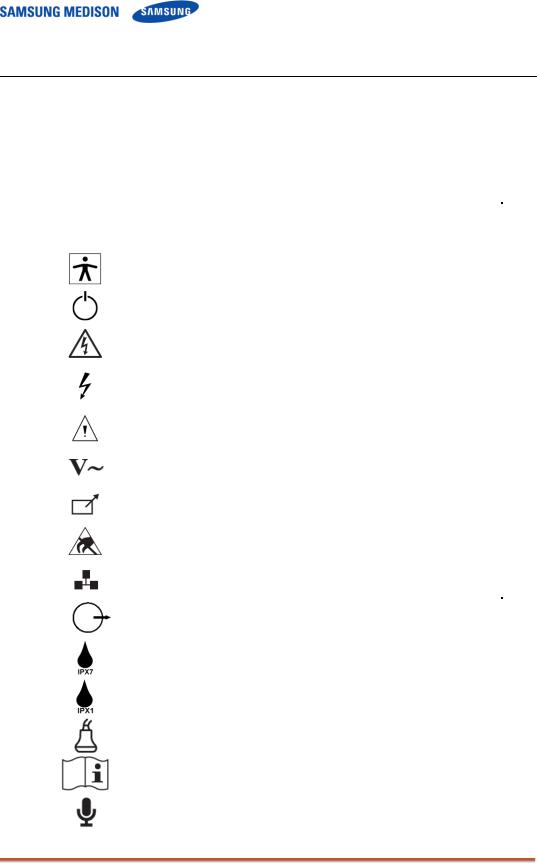
2.2.1Safety Symbols
The International Electro Technical Commission (IEC) has established a set of
symbols for medical electronic equipment, which classifies a connection or warn of potential hazards. The classifications and symbols are shown below.
|
|
|
|
Symbols |
Description |
|
|
|
|
|
|
|
|
Isolated patient connection(Type BF applied part) |
|
|
|
|
|
Power switch (Supplies/cuts the power for product). |
|
|
|
|
|
Indicates a caution for risk of electric shock. |
|
|
|
|
|
Indicates dangerous voltages over 1000V AC or over |
|
|
1500V DC. |
|
|
|
|
|
Warning, Caution |
|
|
|
|
|
AC (alternating current) voltage source |
|
|
|
|
|
Print remote output |
|
|
|
|
|
Electrostatic discharge |
|
|
|
|
|
Network port |
|
|
|
|
|
Output port ( DVI, RGB, B/W, S-VHS, SOUND ) |
|
|
|
|
|
Protection against the effects of immersion. |
|
|
|
|
|
Protection against dripping water. |
|
|
|
|
|
Probe connector |
|
|
|
|
|
Consult Instructions for Use |
|
|
|
|
|
Mic port |
|
|
|
Chapter 2. Safety 2-2 |
|
|
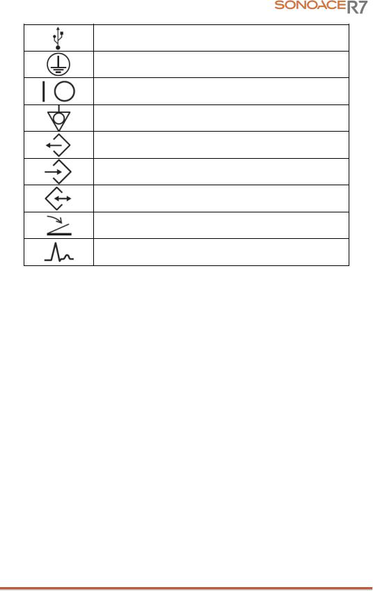
USB port
Power switch (Supplies/cuts the power for product)
Power switch (Supplies/cuts power to the product)
Identifies an equipotential ground.
Data Output port
Data Input port
Data Input/Output port
Foot switch connector
ECG connector
Chapter 2. Safety 2-3

2.2.2LABEL
To protect the system, you may see ‘Warning’ or ‘Caution’ marked on the surface of the product
[ Figure 2-1. Marked on the back sides of the product]
[ Figure 2-2. Marked below OUTLET ]
[ Figure 2-3. Prohibition of seating on Control panel ]
Chapter 2. Safety 2-4

2.3Electrical Safety
This equipment has been verified as a Class I device with Type BF applied parts.
2.3.1Prevention of Electric Shock
In a hospital, dangerous currents are due to the potential differences between connected equipment and touchable conducting parts found in medical rooms. The solution to the problem is consistent equip potential bonding. Medical equipment is connected with connecting leads made up of angled sockets to the equip potential bonding network in medical rooms.
[Figure 2-4] Equip potential bonding
Additional equipment connected to medical electrical equipment must comply with the respective IEC or ISO standards (e.g. IEC 60950 for data processing equipment). Furthermore all configurations shall comply with the requirements for medical electrical systems (see IEC 60601-1-1 or clause 16 of the
 WARNING˙ ˙ ˙ ˙ ˙ ˙ ˙
Electric shock may exist result if this system, including and all of its externally mounted recording and monitoring devices, is not properly grounded.
Do not remove the covers on the system; hazardous voltages are present inside. Cabinet panels
must be in place while the system is in use. All internal adjustments and replacements must be made by a qualified MEDISON Customer Service Department.
Check the face, housing, and cable before use. Do not use, if the face is cracked, chipped, or torn, the housing is damaged, or if the cable is abraded.
Always disconnect the system from the wall outlet prior to cleaning the system.
All patient contact devices, such as probes and ECG leads, must be removed from the patient prior to application of a high voltage defibrillation pulse.
The use of flammable anesthetic gas or oxidizing gases (N20) should be avoided.
 CAUTION˙ ˙ ˙ ˙˙ ˙ ˙
The system has been designed for 100-120VAC and 200-240VAC; you should select the input Outlet voltage of monitor, printer and VCR. Prior to connecting an OEM power cord, verify that the voltage indicated on the power cord matches the voltage rating of the OEM device.
An isolation transformer protects the system from power surges. The isolation transformer continues to operate when the system is in standby.
Do not immerse the cable in liquids. Cables are not waterproof.
The operator does not contact the parts (SIP/SOP) and the patient simultaneously.
Chapter 2. Safety 2-5

2.3.2ECG-Related Information
 WARNING˙ ˙ ˙ ˙ ˙ ˙ ˙
This device is not intended to provide a primary ECG monitoring function, and therefore does not have means of indicating an inoperative electrocardiograph.
Do not use ECG electrodes of HF surgical equipment. Any malfunctions in the HF surgical equipment may result in burns to the patient
Do not use ECG electrodes during cardiac pacemaker procedures or other electrical stimulators.
Do not use ECG leads and electrodes in an operating room.
2.3.3ESD
Electrostatic discharge (ESD), commonly referred to as a static shock, is a naturally occurring phenomenon. ESD is most prevalent during conditions of low humidity, which can be caused by heating or air conditioning. During low humidity conditions, electrical charges naturally build up on individuals, creating static electricity. An ESD occurs when an individual with an electrical energy build-up comes in contact with conductive objects such as metal doorknobs, file cabinets, computer equipment, and even other individuals.
 CAUTION˙ ˙ ˙ ˙˙ ˙ ˙
The level of electrical energy discharged from a system user or patient to an ultrasound system can be significant enough to cause damage to the system or probes.
Always perform the pre-ESD preventive procedures before using connectors marked with the ESD warning label.
-Apply anti-static spray on carpets or linoleum.
-Use anti-static mats.
-Ground the product to the patient table or bed.
It is highly recommended that the user be given training on ESD-related warning symbols and preventive procedures.
2.3.4EMI
Although this system has been manufactured in compliance with existing EMI
(Electromagnetic Interference) requirements, use of this system in the presence of an electromagnetic field can cause momentary degradation of the ultrasound image.
If this occurs often, SAMSUNGMEDISON suggests a review of the environment in which the system is being used, to identify possible sources of radiated emissions. These emissions could be from other electrical devices used within the same room or an adjacent room. Communication devices such as cellular phones and pagers can cause these emissions. The existence of radios, TVs, or microwave transmission equipment nearby can also cause interference.
 CAUTION˙ ˙ ˙ ˙˙ ˙ ˙
In cases where EMI is causing disturbances, it may be necessary to relocate this system.
Chapter 2. Safety 2-6

2.3.5EMC
The testing for EMC(Electromagnetic Compatibility) of this system has been performed according to the international standard for EMC with medical devices (IEC60601-1-2). This IEC standard was adopted in Europe as the European norm (EN60601-1-2).
2.3.5.1Guidance and manufacturer’s declaration - electromagnetic emission
This product is intended for use in the electromagnetic environment specified below.
The customer or the user of this product should assure that it is used in such an environment.
|
Emission test |
|
|
Compliance |
|
|
Electromagnetic environment -guidance |
|
|
|
|
|
|
|
|||
|
|
|
|
|
|
|
|
|
|
|
|
|
|
|
|
The Ultrasound System uses RF energy only |
|
|
RF Emission |
|
|
|
|
for its internal function. Therefore, its RF |
||
|
|
Group 1 |
|
emissions are very low and are not likely to |
||||
|
CISPR 11 |
|
|
|||||
|
|
|
|
|
cause any interference in nearby electronic |
|||
|
|
|
|
|
|
|
equipment. |
|
|
RF Emission |
|
Class B |
|
|
|
||
|
CISPR 11 |
|
|
The Ultrasound System is suitable for use in all |
||||
|
|
|
|
|
||||
|
|
|
|
|
establishments, including domestic |
|||
|
|
|
|
|
|
|
||
|
Harmonic Emission |
|
|
|
|
|||
|
|
Class A |
|
establishments and those directly connected to |
||||
|
IEC 61000-3-2 |
|
|
the public low-voltage power supply network |
||||
|
|
|
|
|
||||
|
|
|
|
|
that supplies building used for domestic |
|||
|
|
|
|
|
|
|
||
|
|
|
|
|
|
|
||
|
Flicker Emission |
|
Complies |
|
purpose. |
|||
|
IEC 61000-3-3 |
|
|
|
|
|||
|
|
|
|
|
|
|
||
|
|
|
|
|
|
|
|
|
2.3.5.2Approved Cables, Transducers and Accessories for EMC
1)Approved Cable for Electromagnetic Compliance
Cables connected to this product may affect its emissions;
Use only the cable types and lengths listed below table.
|
Cable |
|
|
Type |
|
|
Length |
|
|
|
|
|
|
|
|||
|
|
|
|
|
|
|
|
|
|
VGA |
|
Shielded |
|
Normal |
|||
|
Parallel |
|
Shielded |
|
Normal |
|||
|
RS232C |
|
Shielded |
|
Normal |
|||
|
USB |
|
Shielded |
|
Normal |
|||
|
LAN(RJ45) |
|
Twisted pair |
|
Any |
|||
|
S-Video |
|
Shielded |
|
Normal |
|||
|
Foot Switch |
|
Shielded |
|
2.5m |
|||
|
B/W Printer |
|
Unshielded Coaxial |
|
Normal |
|||
|
MIC |
|
Unshielded |
|
Any |
|||
|
Printer Remote |
|
Unshielded |
|
Any |
|||
|
Audio R.L |
|
Shielded |
|
Normal |
|||
|
VHS |
|
Shielded |
|
Normal |
|||
|
ECG AUX input |
|
Shielded |
|
< 3m |
|||
2) Approved Transducer for Electromagnetic Compliance
The probe listed in ‘Chapter 9. Probes’ when used with this product, have been tested to comply with the group1 class B emission as required by International Standard CISPR 11.
Chapter 2. Safety 2-7

3) Approved Accessories for Electromagnetic Compliance Accessories used with this product may effect its emissions
 CAUTION˙ ˙ ˙ ˙˙ ˙ ˙
When connecting other customer-supplied accessories to the system, such as a remote printer or VCR, it is the user’s responsibility to ensure the electromagnetic compatibility of the system. Use only CISPR 11 or CISPR 22, CLASS B compliant
devices
 WARNING˙ ˙ ˙ ˙ ˙ ˙ ˙
The use of cables, transducers, and accessories other than those specified may result increased emission or decreased Immunity of the Ultrasound System.
|
Immunity test |
|
|
|
IEC 60601 |
|
|
Compliance level |
|
|
Electromagnetic environment – |
|
|
|
|
|
|
|
|
|
|
|
|||||
|
|
|
|
Test level |
|
|
|
|
guidance |
|
|||
|
|
|
|
|
|
|
|
|
|
|
|
||
|
|
|
|
|
|
|
|
|
|
|
|
|
|
|
Electrostatic |
|
±6KV Contact |
|
±6KV |
Contact |
|
Floors should be wood, concrete |
|||||
|
|
|
|
or ceramic tile. If floors are |
|||||||||
|
|
|
|
|
|
||||||||
|
|
|
|
|
|
|
|
|
|
|
|
||
|
discharge (ESD) |
|
|
|
|
|
|
|
|
|
covered with synthetic material, |
||
|
IEC 61000-4-2 |
|
±8KV |
air |
|
±8KV |
air |
|
the relative humidity should be at |
||||
|
|
|
|
|
|
|
|
|
|
least 30%. |
|||
|
|
|
|
|
|
|
|
|
|
|
|
||
|
|
|
|
|
|
|
|
|
|
|
|
||
|
Electrical fast |
|
±2KV |
for power supply |
|
±2KV for power |
|
Mains power quality should be that |
|||||
|
|
|
|
|
|
of a typical commercial or hospital |
|||||||
|
transient/burst |
|
lines |
|
|
|
supply lines |
|
|||||
|
|
|
|
|
|
environment. |
|||||||
|
|
|
|
|
|
|
|
|
|
||||
|
|
|
|
±1KV for input/output |
|
±1KV for input/ |
|
||||||
|
|
|
|
|
|
|
|
||||||
|
IEC 61000-4-4 |
|
lines |
|
|
|
output lines |
|
|
|
|||
|
|
|
|
|
|
|
|
|
|
|
|
||
|
|
|
|
|
|
|
|
|
|
|
|
||
|
Surge |
|
±1KV differential mode |
|
±1KV differential mode |
|
Mains power quality should be that |
||||||
|
|
|
|
|
|
|
|
||||||
|
IEC 61000-4-5 |
|
±2KV common mode |
|
±2KV common mode |
|
of a typical commercial or hospital |
||||||
|
|
|
|
environment. |
|||||||||
|
|
|
|
|
|
|
|
|
|
||||
|
|
|
|
|
|
|
|
|
|
|
|
||
|
|
|
|
|
|
|
|
||||||
|
Voltage dips, short |
|
<5% Uт |
|
<5% Uт |
|
Mains power quality should be that |
||||||
|
interruptions and |
|
(>95% dip in Uт) |
|
(>95% dip in Uт) |
|
of a typical commercial or hospital |
||||||
|
voltage variations |
|
for 0.5cycle |
|
for 0.5cycle |
|
environment. If the user of this |
||||||
|
on power supply |
|
|
|
|
|
|
|
|
|
product requires continued |
||
|
input lines |
|
40% Uт |
|
40% Uт |
|
operation during power mains |
||||||
|
|
|
|
(60% dip in Uт ) |
|
(60% dip in Uт ) |
|
interruptions, it is recommended |
|||||
|
IEC 61000-4-11 |
|
for 5 cycle |
|
for 5 cycle |
|
that this product be powered from |
||||||
|
|
|
|
|
|
|
|
|
|
|
|
an uninterruptible power supply or |
|
|
|
|
|
70% Uт |
|
70% Uт |
|
a battery. |
|||||
|
|
|
|
(30% dip in Uт) |
|
(30% dip in Uт) |
|
|
|
||||
|
|
|
|
for 25 cycle |
|
for 25 cycle |
|
|
|
||||
|
|
|
|
<5% Uт |
|
<5% Uт |
|
|
|
||||
|
|
|
|
(<95% dip in Uт ) |
|
(<95% dip in Uт ) |
|
|
|
||||
|
|
|
|
for 5 s |
|
|
|
for 5 s |
|
|
|
|
|
|
Power frequency |
|
|
|
|
|
|
|
|
|
Power frequency magnetic fields |
||
|
(50/60Hz) |
|
|
|
|
|
|
|
|
|
should be at levels characteristic |
||
|
magnetic field |
|
3 A/m |
|
|
|
3 A/m |
|
|
|
of a typical location in a typical |
||
|
|
|
|
|
|
|
|
|
|
|
|
commercial or hospital |
|
|
IEC 61000-4-8 |
|
|
|
|
|
|
|
|
|
environment. |
||
Chapter 2. Safety 2-8
 Loading...