


NETWORK CAMERA
User Manual
SNO-7082R

Network Camera
User Manual
Copyright
©2013 Samsung Techwin Co., Ltd. All rights reserved.
Trademark
 is the registered logo of Samsung Techwin Co., Ltd. The name of this product is the registered trademark of Samsung Techwin Co., Ltd.
Other trademarks mentioned in this manual are the registered trademark of their respective company.
Restriction
Samsung Techwin Co., Ltd shall reserve the copyright of this document. Under no circumstances, this document shall be reproduced, distributed or changed, partially or wholly, without formal authorization of Samsung Techwin.
Disclaimer
Samsung Techwin makes the best to verify the integrity and correctness of the contents in this document, but no formal guarantee shall be provided. Use of this document and the subsequent results shall be entirely on the user’s own responsibility. Samsung Techwin reserves the right to change the contents of this document without prior notice.
Design and specifications are subject to change without prior notice.
The default password can be exposed to a hacking thread so it is recommended to change the password after installing the product.
Note that the security and other related issues caused by the unchanged password shall be responsible for the user.

overview
Important Safety Instructions
1. |
Read these instructions. |
|
|
2. |
Keep these instructions. |
|
|
3. |
Heed all warnings. |
● |
|
4. |
Follow all instructions. |
overview |
|
|
|
||
5. |
Do not use this apparatus near water. |
|
|
6. |
Clean only with dry cloth. |
|
|
7. |
Do not block any ventilation openings, Install in accordance with the manufacturer’s |
|
|
8. |
instructions. |
|
|
Do not install near any heat sources such as radiators, heat registers, stoves, or other |
|
|
|
9. |
apparatus (including amplifiers) that produce heat. |
|
|
Do not defeat the safety purpose of the polarized or grounding-type plug. A polarized |
|
|
|
|
plug has two blades with one wider than the other. A grounding type plug has two |
|
|
|
blades and a third grounding prong. The wide blade or the third prong are provided for |
|
|
|
your safety. If the provided plug does not fit into your outlet, consult an electrician for |
|
|
10. |
replacement of the obsolete outlet. |
|
|
Protect the power cord from being walked on or pinched particularly at plugs, |
|
|
|
11. |
convenience receptacles, and the point where they exit from the apparatus. |
|
|
Only use attachments/ accessories specified by the manufacturer. |
|
|
|
12. |
Use only with the cart, stand, tripod, bracket, or table specified by |
|
|
|
the manufacturer, or sold with the apparatus. When a cart is used, |
|
|
|
use caution when moving the cart/apparatus combination to avoid |
|
|
13. |
injury from tip-over. |
|
|
Unplug this apparatus during lighting storms or when unused for |
|
|
|
14. |
long periods of time. |
|
|
Refer all servicing to qualified service personnel. Servicing is required when the apparatus |
|
|
|
|
has been damaged in any way, such as power-supply cord or plug is damaged, liquid has |
|
|
|
been spilled or objects have fallen into the apparatus, the apparatus has been exposed to |
|
|
|
rain or moisture, does not operate normally, or has been dropped. |
|
|
English _3
overview
WARNING
TO REDUCE THE RISK OF FIRE OR ELECTRIC SHOCK, DO NOT EXPOSE THIS PRODUCT TO RAIN OR MOISTURE. DO NOT INSERT ANY METALLIC OBJECT THROUGH THE VENTILATION GRILLS OR OTHER OPENNINGS ON THE EQUIPMENT.
Apparatus shall not be exposed to dripping or splashing and that no objects filled with liquids, such as vases, shall be placed on the apparatus.
To prevent injury, this apparatus must be securely attached to the Wall/ceiling in accordance with the installation instructions.
CAUTION
CAUTION
RISK OF ELECTRIC SHOCK.
DO NOT OPEN
CAUTION : TO REDUCE THE RISK OF ELECTRIC SHOCK.
DO NOT REMOVE COVER (OR BACK).
NO USER SERVICEABLE PARTS INSIDE.
REFER SERVICING TO QUALIFIED SERVICE PERSONNEL.
EXPLANATION OF GRAPHICAL SYMBOLS
The lightning flash with arrowhead symbol, within an equilateral triangle, is intended to alert the user to the presence of “dangerous voltage” within the product’s enclosure that may be of sufficient magnitude to constitute a risk of electric shock to persons.
The exclamation point within an equilateral triangle is intended to alert the user to the presence of important operating
and maintenance (servicing) instructions in the literature accompanying the product.
4_ overview

Battery
Batteries(battery pack or batteries installed) shall not be exposed to excessive heat such as sunshine, fire or the like.
Disconnection Device
Disconnect the main plug from the apparatus, if it’s defected. And please call a repair man in your location.
When used outside of the U.S., it may be used HAR code with fittings of an approved agency is employed.
CAUTION
Risk of explosion if battery is replaced by an incorrect type. Dispose of used batteries according to the instructions.
These servicing instructions are for use by qualified service personnel only. To reduce the risk of electric shock do not perform any servicing other than that contained in the operating instructions unless you are qualified to do so.
The BNC Out terminal of the product is provided for easier installation, and is not recommended for monitoring purposes.
If you keep the BNC cable connected, a risk of lightening may cause damage or malfunction to the product.
Please use the input power with just one camera and other devices must not be connected.
The ITE is to be connected only to PoE networks without routing to the outside plant.
overview ●
English _5

overview
Please read the following recommend safety precautions carefully.
yyDo not place this apparatus on an uneven surface.
yyDo not install on a surface where it is exposed to direct sunlight, near heating equipment or heavy cold area.
yyDo not place this apparatus near conductive material. yyDo not attempt to service this apparatus yourself. yyDo not place a glass of water on the product.
yyDo not install near any magnetic sources. yyDo not block any ventilation openings. yyDo not place heavy items on the product.
User’s Manual is a guidance book for how to use the products. The meaning of the symbols are shown below.
yyReference : In case of providing information for helping of product’s usages
yyNotice : If there’s any possibility to occur any damages for the goods and human caused by not following the instruction
Please read this manual for the safety before using of goods and keep it in the safe place.
6_ overview

CONTENTS
overview |
9 |
Product Features |
3 |
3 |
Important Safety Instructions |
10 |
Recomended PC Specifications |
|
11 |
Recomended SD/SDHC Memory |
|
11 |
Card Specifications |
|
|
What’s Included |
|
|
12 |
At a Glance |
installation & |
15 |
Installation |
connection |
16 |
Memory Card Information |
15 |
16 |
Connecting with other Device |
overview ●
network connection and setup
20
20 Connecting the Camera Directly to Local Area Networking
21 Connecting the Camera Directly to a DHCP Based DSL/Cable Modem
22 Connecting the Camera Directly to a PPPoE Modem
23 Connecting the Camera to a Broadband Router with the PPPoE/Cable Modem
24 Buttons used in IP Installer
25 Static IP Setup
29 Dynamic IP Setup
30 Port Range Forward (Port Mapping) Setup
32 Connecting to the Camera from a Shared Local PC
32 Connecting to the Camera from a Remote PC via the Internet
English _7

overview
web viewer |
34 |
Login |
33 |
33 |
Connecting to the Camera |
35 |
Installing Silverlight Runtime |
|
39 |
Installing STW WebViewer Plugin |
|
40 |
Using the Live Screen |
|
|
43 |
Playing the recorded video |
setup screen |
48 |
Video & Audio Setup |
48 |
48 |
Setup |
62 |
Network Setup |
|
71 |
Event Setup |
|
87 |
System Setup |
|
appendix |
98 |
Product Overview |
94 |
94 |
Specification |
99 |
Troubleshooting |
|
101 |
Open Source Announcement |
8_ overview

Product Features
yy Dustproof/Waterproof (IP66)
The dustproof and waterproof design makes you feel at ease when installing the product outdoors or exposing it to rain.
yy SSNR3 (Samsung Super Noise Reduction)
The high-performance DSP chip effectively removes the GAIN noise of low light level and shows a clear and sharp image even in dark places.
yy Day & Night (ICR)
It automatically detects the time change of the day to switch to a mode that is appropriate to the current scene. In a daylight scene, it switches to the color mode for maintaining the optimal color tones while it, at night, switches to B/W mode for identifying the low contrast scene.
yy IR mode
If the IR indicator turns on, the product switches to the IR mode for preventing an object from being too bright, which helps you identify the object in near distance.
yy Visibility: 30m
In B/W mode, the IR indicator turns on with the effective visibility of 30m at 0 Lux. yy SSDR (Samsung Super Dynamic Range)
For a scene showing a great contrast difference such as backlight scene, the product maintains the bright areas while selectively making the dark areas brighter to balance the overall contrast.
yy Others
Other features include: HLC (High Light Compensation), SENS-UP, V-REV, H-REV, D-ZOOM, SHARPNESS, Motion Detection, PRIVACY.
yy Full HD Video Quality yy Multi-Streaming
This network camera can display videos in different resolutions and qualities simultaneously using different CODECs.
yy Web Browser-based Monitoring
Using the Internet web browser to display the image in a local network environment. yy Alarm
If an event occurs, the event-related video will be transferred to the FTP/email specified by the user or saved to the SD memory, or the event signal will be sent to the Alarm Out port.
yy Built-in SD Memory
This product is equipped with an internal 4GB memory card. yy Tampering Detection
Detects tempering attempts on video monitoring.
overview ●
English _9

overview
yy Motion Detection
Detects motion from the camera’s video input.
yy Intelligent Video Analysis
Analyzes video to detect logical events of specified conditions from the camera’s video input.
yy Face Detection
Detects faces from the camera’s video input. yy Audio Detection
Detects sound louder than a certain level specified by user. yy Auto Detection of Disconnected Network
Detects network disconnection before triggering an alarm. yy ONVIF Compliance
This product supports ONVIF.
For more information, refer to www.onvif.org.
Recomended PC Specifications
yy CPU : Intel Core 2 Duo 2.4GHz or higher
`` Web Plug-in is optimized to SSE 4.1 Instruction Set.
yy Operating System : Windows XP, VISTA, 7, Mac OS yy Resolution : 1280X1024 pixels or higher (32 bit color) yy RAM : 2GB or higher
yy Web Browser : Internet Explorer 7.0 or Higher, Firefox 9.0 or Higher, Chrome 15.0 or Higher, *Safari 5.1 or Higher
`` Neither a beta test version unlike the version released in the company website nor the developer version will be supported.
`` It is recommended to connect to IPv6 in Windows 7. `` For Mac OSX, only the Safari browser is supported.
yy Video Memory : 256MB or higher
JJ``
``
If the driver of the video graphic adapter is not installed properly or is not the latest version, the video may not be played properly.
For a multi-monitoring system involving at least 2 monitors, the playback performance can be deteriorated depending on the system.
10_ overview
Recomended SD/SDHC Memory Card Specifications
yy 4GB ~ 32GB
yy For your camera, we recommend you use a memory card from the following manufacturers:
SD/SDHC Memory Card : Sandisk, Transcend
yy It is recommended to use memory cards of at least class 6 speed.
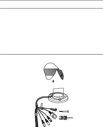
What’s Included
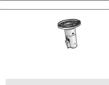
Please check if your camera and accessories are all included in the product package.
Appearance |
Item Name |
Quantity |
Description |
|
Camera |
1 |
|
|
Instruction book, |
2 |
|
|
Installer S/W CD, |
|
|
|
CMS S/W DVD |
|
|
|
Quick Guide |
1 |
|
|
(Optional) |
|
|
|
|
|
|
|
Tapping Screw |
3 |
Used for installation on the wall or ceiling |
|
L Wrench |
1 |
Used to adjust the camera orientation |
|
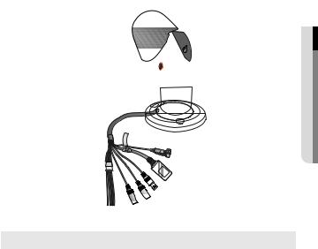
Sunshield |
1 |
It protects the camera from the direct |
|
sunlight. |
||
|
|
|
|
|
Sunshield Hold |
1 |
It fixes the sunshield with the camera. |
overview ●
English _11
overview
At a Glance
Front Side
Item |
Description |
a Sunshield |
It protects the camera from the direct sunlight. |
|
|
b Sunshield Hold |
It fixes the sunshield with the camera. |
|
|
c IR LED |
These infrared LED's are controlled by the illumination sensor. |
|
|
d Illumination Sensor |
Detects incoming light to control the IR LED. |
MM`` Wipe out a dirty surface of the lens softly with a lens tissue or cloth to which you have applied ethanol.
12_ overview
Rear Side
overview ●
Item |
Description |
a Power Port |
Used to plug the power cable. |
b Network Port |
Used to connect a PoE or LAN cable. |
|
|
c Video Output Port |
Connected to the monitor so that you can check the video from the camera. |
(for installation) |
|
d Audio In Jack |
Used to connect to a microphone. |
|
|
e Audio Out Jack |
Used to connect to speakers. |
|
|
English _13

overview
Item |
|
|
Description |
|
BROWN (ARM-IN) |
Used to connect the alarm input sensor. |
|
|
SKY-BLUE (GND) |
Earth-grounding port for external signal. |
|
|
YELLOW |
Used to connect the alarm output signal. |
|
|
(ARM-OUT) |
||
f I/O Port |
|
|
|
ORANGE (A-COM) |
Common port where the alarm output signal is |
||
|
connected. |
||
|
|
||
|
WHITE/GRAY |
Resets the camera settings to the default. |
|
|
` |
To perform the factory reset, peel off the white and |
|
|
(RESET) |
` |
gray wire, and then touch the two wires together |
|
|
|
for approximately 10 seconds. |
14_ overview
installation & connection
Installation
JJ`` This camera is waterproof and in compliance with the IP66 spec, but the jack connected to the external cable is not. You are recommended to install this product below the edge of eaves to prevent the cable from being externally exposed.
Outdoor installation
When you install it outside of the building, please waterproof it with waterproof butyl rubber |
||||||||||||||
tape (can be purchased in stores) so that water does not leak from the gap of the cable |
||||||||||||||
connected to the outside. |
|
|
|
|
|
|
|
|
|
|
|
|
||
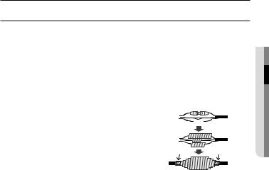
1. Connect the power, I/O, BNC, and LAN |
|
|
|
|
|
|
|
|
|
|
|
|
|
|
|
Camera |
|
|
|
|
|
|
|
|
|
|
System |
||
cables. |
|
|
|
|
|
|
|
|
|
|
|
|
|
|
2. Wrap the black cable jacket (Area A) and the |
|
|
|
|
|
|
|
|
|
|
|
|
|
|
cable connection area with waterproof (butyl |
Camera |
|
|
|
|
|
|
|
|
|
|
System |
||
rubber) tape so that more than half of the |
|
|
|
|
|
|
|
|
|
|
|
|
||
|
|
|
|
|
|
|
|
|
|
|
|
|||
butyl rubber tape is overlapped. |
|
A |
|
|
|
|
|
|
|
|
A |
|||
|
|
|
|
|
|
|
|
|
|
|
|
|
|
|
|
`` If the cable jacket is not waterproofed properly, |
Camera |
|
|
|
|
|
|
|
|
|
|
System |
|
JJ |
|
|
|
|
|
|
|
|
|
|
|
|
||
|
|
|
|
|
|
|
|
|
|
|
|
|||
then it can directly cause leakage. Make sure to |
|
|
|
|
|
|
|
|
|
|
|
|
||
|
protect the cable with a dense layer of taping. |
|
|
|
|
|
|
|
|
|
|
|
|
|
`` Waterproof butyl tape is made of butyl rubber that can be stretched to twice its normal length.
connectionin&sta●ationll
English _15
installation & connection
Memory Card Information
What is a memory card?
The memory card is an external data storage device that has been developed to offer an entirely new way to record and share video, audio, and text data using digital devices.
Memory Card Instructions
yy This product is equipped with an internal 4GB memory card.
Do not dismantle this product by yourself for a reason such as waterproofing.
yy If you encounter a problem with the installation, contact the manufacturer for technical assistance.
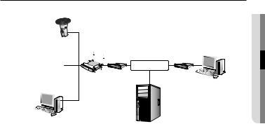
Connecting with other Device

 Power
Power
Ethernet
Monitor (for installation)
16_ installation & connection

JJ`` The BNC Out terminal of the product is provided for easier installation, and is not recommended for monitoring purposes.
If you keep the BNC cable connected, a risk of lightening may cause damage or malfunction to the product.
Ethernet Connection
Connect the Ethernet cable to the local network or to the Internet.
Power Supply
Use the screwdriver to connect each line (+, –) of the power cable to the corresponding power port of the camera.
JJ`` Be careful not to reverse the polarity when you connect the power cable.
You can also use a router featuring PoE (Power over Ethernet) to supply power to the camera.
`` If PoE and DC12V power or PoE and AC 24V are supplied simultaneously, the product will operate with the first applied power source.
`` If using PoE and DC 12V adaptor, the heater will not operate at all.
If the heater must be operated due to the installation environment, please use the AC 24V adaptor. The adaptor is sold separately.
`` AC 24V can be applied in non-polarity.
`` Use AC 24V in a low-temperature place of less than -10°C.
`` Please make sure the monitor and camera are turned off when connecting them.
connectionin&sta●ationll
English _17
installation & connection
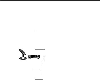
Connecting to Audio Input/Output
Speaker |
|
Microphone |
PC |
|
|
|
Network |
Microphone |
Amp |
|
|
Microphone |
|
CAUTION:Be ware of the Rated Voltage and Polarity of the power connection.
Speaker Amp
1.Connect the AUDIO IN port of the camera with the microphone directly or LINE OUT port of the amplifier that the microphone is connected to.
2.Connect the AUDIO OUT port of the camera with the LINE IN port of the speaker.
3.Check the specifications for audio input.
yy Audio Codec
Audio In: G.711 PCM (Bit Rate: 64kbps / Sampling Frequency: 8kHz), G.726 ADPCM (Bit Rate: 16Kbps, 24Kbps, 32Kbps, 40Kbps / Sampling Frequency: 8kHz) Audio Out: G.711 PCM (Bit Rate: 64kbps / Sampling Frequency: 8kHz)
yy Full duplex Audio yy Audio in
Used for mono signal line input (Max.2.4 Vpp) yy Audio out
Used for mono signal line output (Max.2.4 Vpp) yy Line out impedance
600Ω
18_ installation & connection

Connecting the alarm I/O signal
Connect the alarm input/output signal using the I/O ports of the cable.
connectionin&sta●ationll
(RESET) GRAY (RESET) WHITE COM)-ORANGE(A OUT)-(ARM YELLOW (GND) BLUE-SKY IN)-(ARM BROWN
|
ALARM SENSOR |
|
|
Port |
Description |
Port |
Description |
ARM-IN |
Alarm Input Sensor Port |
GND |
Earth-grounding Port |
ARM-OUT |
Alarm out |
A-COM |
Alarm Out (common) |
To connect the alarm input signal
Connect one strand of each signal line (2-strand) of the sensors to the [ARM-IN] port, and connect the other strand to the [GND] port.
To connect the alarm output signal
Connect one strand of each signal line (2-strand) of an external device to the [ARM-OUT] port, and connect the other stand to the [A-COM] port.
English _19
network connection and setup
You can set up the network settings according to your network configurations.
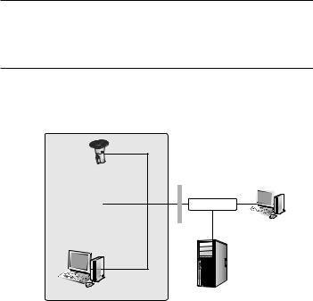
Connecting the Camera Directly to Local Area Networking
Connecting to the camera from a local PC in the LAN
1.Launch an Internet browser on the local PC.
2.Enter the IP address of the camera in the address bar of the browser.
Camera |
|
|
Switch |
|
INTERNET |
|
Firewall |
External Remote PC |
Camera |
|
|
|
|
|
|
|
DDNS Server |
|
|
(Data Center, KOREA) |
Local PC
<Local Network>
MM`` A remote PC in an external Internet out of the LAN network may not be able to connect to the camera installed in the intranet if the port-forwarding is not properly set or a firewall is set. In this case, to resolve the problem, contact your network administrator.
`` By factory default, the IP address will be assigned from the DHCP server automatically. If there is no DHCP server available, the IP address will be set to 192.168.1.100.
To change the IP address, use the IP Installer.
For further details on IP Installer use, refer to “Static IP Setup”. (Page 25)
20_ network connection and setup
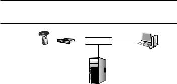
Connecting the Camera Directly to a DHCP Based DSL/Cable Modem
DSL/Cable |
INTERNET |
|
External Remote PC |
||
Modem |
||
Camera |
|
DDNS Server
(Data Center, KOREA)
1.Use the cross LAN cable to connect the network cable directly to your PC.
2.Run the IP Installer and change the IP address of the camera so that you can use the web browser on your desktop to connect to the Internet.
3.Use the Internet browser to connect to the web viewer.
4.Move to [Setup] page.
5.Move to [Network] – [DDNS] and configure the DDNS settings.
6.Move to [Network] – [Interface], and set the network type to [DHCP].
7.Connect the camera, which was removed from your PC, directly to the modem.
8.Restart the camera.
MM`` For registering the DDNS settings, refer to “Registering with DDNS”. (page 65)
`` For configuring the DDNS settings, refer to “DDNS”. (page 64) `` For setting the network type, refer to “Interface”. (page 62)
etupd s
networan connection● k
English _21
network connection and setup
Connecting the Camera Directly to a PPPoE Modem
INTERNET 
PPPoE Modem
External Remote PC
Camera
DDNS Server
(Data Center, KOREA)
1.Use the cross LAN cable to connect the network cable directly to your PC.
2.Run the IP Installer and change the IP address of the camera so that you can use the web browser on your desktop to connect to the Internet.
3.Use the Internet browser to connect to the web viewer.
4.Move to [Setup] page.
5.Move to [Network] – [DDNS] and configure the DDNS settings.
6.Move to [Network] – [Interface], and set the network type to [PPPoE].
7.Connect the camera, which was removed from your PC, directly to the modem.
8.Restart the camera.
MM`` For registering the DDNS settings, refer to “Registering with DDNS”. (page 65)
`` For configuring the DDNS settings, refer to “DDNS”. (page 64) `` For setting the network type, refer to “Interface”. (page 62)
22_ network connection and setup
Connecting the Camera to a Broadband Router with the PPPoE/Cable Modem
This is for a small network environment such as homes, SOHO and ordinary shops.
Camera |
|
|
|
|
|
|
|
INTERNET |
|
|
Broadband |
PPPoE or |
PPPoE or |
|
|
Cable Modem |
Cable Modem |
External Remote |
|
Camera |
Router |
|
|
|
|
|
|
PC |
|
|
|
|
DDNS Server |
|
|
|
|
(Data Center, KOREA) |
|
Local PC
Configuring the network settings of the local PC connected to a Broadband Router
Configuring the network settings of the local PC connected to a Broadband Router, follow the instructions below.
yy Select : <Network Neighborhood> <Properties> <Local Area Connection> <Properties> <General> <Internet Protocol (TCP/IP)> <Properties> <Obtain an IP address automatically> or <Use the following IP address>.
yy Follow the instructions below if you select <Use the following IP address>:
ex1) If the address (LAN IP) of the Broadband Router is 192.168.1.1 IP address : 192.168.1.100
Subnet Mask : 255.255.255.0
Default Gateway : 192.168.1.1
ex2) If the address (LAN IP) of the Broadband Router is 192.168.0.1 IP address : 192.168.0.100
Subnet Mask : 255.255.255.0
Default Gateway : 192.168.0.1
ex3) If the address (LAN IP) of the Broadband Router is 192.168.xxx.1 IP address : 192.168.xxx.100
Subnet Mask : 255.255.255.0
Default Gateway : 192.168.xxx.1
MM`` For the address of the Broadband Router, refer to the product’s documentation.
`` For more information about port forwarding of the broadband router, refer to “Port Range Forward (Port Mapping) Setup”. (Page 30)
etupd s
networan connection● k
English _23
network connection and setup
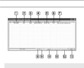
Buttons used in IP Installer
Item |
Description |
a Device Name |
Model name of the connected camera. |
Click the column to sort the list by model name. |
|
|
However, search will be stopped if clicked during the search. |
b Alias |
This function is not currently implemented. |
c Mode |
Displays either <Static>, <Dynamic> or <PPPoE> for the current network |
connection status. |
|
d MAC(Ethernet) |
Ethernet address for the connected camera. |
Click the column to sort the list by Ethernet address. |
|
Address |
However, search will be stopped if clicked during the search. |
e IP Address |
IP address. |
Click the column to sort the list by IP address. |
|
|
However, search will be stopped if clicked during the search. |
f Protocol |
Network setting for the camera. |
The factory default is “IPv4”. |
|
|
Cameras with the IPv6 setting will be displayed “IPv6”. |
24_ network connection and setup

etupd s
Item |
Description |
g URL |
DDNS URL address enabling access from the external Internet. |
However, this will be replaced with the <IP Address> of the camera if |
|
|
DDNS registration has failed. |
h IPv4 |
Scans for cameras with the IPv4 setting. |
i IPv6 |
Scans for cameras with the IPv6 setting. |
Activated in an IPv6 compliant environment only. |
|
j Search |
Scans for cameras that are currently connected to the network. |
However, this button will be grayed out if neither IPv4 nor IPv6 is checked. |
|
k Auto Set |
The IP Installer automatically configures the network settings. |
l Manual Set |
You should configure the network settings manually. |
m Exit |
Exits the IP Installer program. |
MM`` For the IP installer, use only the installer version provided in the installation CD or use the latest one if available. You can download the latest version from the Samsung web site (www.samsungcctv.com).
Static IP Setup
Manual Network Setup
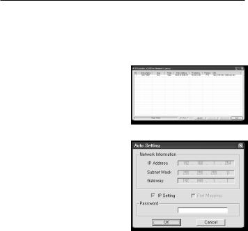
Run <IP Installer_v2.XX.exe> to display the camera search list.
At the initial startup, both [Auto Set] and [Manual Set] will be grayed out.
MM`` For cameras found with the IPv6 setting, these buttons will be grayed out as the cameras do not support this function.
1.Select a camera in the search list. Check the MAC address of the camera on the camera’s label.
Both the [Auto Set] and [Manual Set] buttons will be activated.
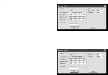
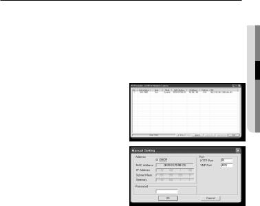
2.Click [Manual Set].
The Manual Setting dialog appears. The default values of <IP Address>,
<Subnet Mask>, <Gateway>, <HTTP Port> and <VNP Port> of the camera will be displayed.
networan connection● k
English _25
network connection and setup
3.In the <Address> pane, provide the necessary information.
yy MAC (Ethernet) Address : The MAC address imprinted on the camera label is automatically displayed and requires no user setting.
MM`` You can configure the static IP settings only if the DHCP checkbox is unchecked.
If not using a Broadband Router
For setting <IP Address>, <Subnet Mask>, and <Gateway>, contact your network administrator.
4.In the <Port> pane, provide necessary information.
yy HTTP Port : Used to access the camera using the Internet browser, defaulted to 80.
yy VNP Port : Used to control the video signal transfer, defaulted to 4520.
5.Enter the password.
Enter the password of “admin” account, which was used to access the camera. The default password is “4321”.
JJ`` The default password can be exposed to a hacking thread so it is recommended to change the password after installing the product.
Note that the security and other related issues caused by the unchanged password shall be responsible for the user.
`` If you want to change the password, refer to “Administrator password change” of the user setup. (page 89)
6.Click [OK].
Manual network setup will be completed.
26_ network connection and setup
If using a Broadband Router
yy IP Address : Enter an address falling in the IP range provided by the Broadband Router.
ex) 192.168.1.2~254, 192.168.0.2~254, 192.168.XXX.2~254
yy Subnet Mask : The <Subnet Mask> of the Broadband Router will be the <Subnet Mask> of the camera.
yy Gateway : The <Local IP Address> of
the Broadband Router will be the <Gateway> of the camera.
MM`` The settings may differ depending on the connected Broadband Router model. For more information, refer to the user manual of the applicable router.
`` For more information about port forwarding of the broadband router, refer to “Port Range Forward (Port Mapping) Setup”. (Page 30)
If the Broadband Router has more than one camera connected
Configure the IP related settings and the Port related settings distinctly with each other. ex)
|
Category |
Camera #1 |
Camera #2 |
|
IP related settings |
|
IP Address |
192.168.1.100 |
192.168.1.101 |
|
Subnet Mask |
255.255.255.0 |
255.255.255.0 |
|
|
|
Gateway |
192.168.1.1 |
192.168.1.1 |
Port related settings |
|
HTTP Port |
8080 |
8081 |
|
VNP Port |
4520 |
4521 |
|
MM`` If the <HTTP Port> is set other than 80, you must provide the <Port> number in the address bar of the Internet browser before you can access the camera.
ex) http://IP address : HTTP Port http://192.168.1.100:8080
etupd s
networan connection● k
English _27
network connection and setup
Auto Network Setup
Run <IP Installer_v2.XX.exe> to display the camera search list.
At the initial startup, both [Auto Set] and [Manual Set] will be grayed out.
MM`` For cameras found with the IPv6 setting, these buttons will be grayed out as the cameras do not support this function.
1.Select a camera in the search list. Check the MAC address of the camera on the camera’s label.
Both the [Auto Set] and [Manual Set] buttons will be activated.
2.Click [Auto Set].
The Auto Setting dialog appears. The <IP Address>, <Subnet Mask>,
and <Gateway> will be set automatically.
3.Enter the password.
Enter the password of “admin” account, which was used to access the camera. The default password is “4321”.
JJ`` The default password can be exposed to a hacking thread so it is recommended to change the password after installing the product.
Note that the security and other related issues caused by the unchanged password shall be responsible for the user.
`` If you want to change the password, refer to “Administrator password change” of the user setup. (page 89)
4.Click [OK].
Auto network setup will be completed.
28_ network connection and setup
Dynamic IP Setup
Dynamic IP Environment Setup
yy Example of the Dynamic IP environment
-- If a Broadband Router, with cameras connected, is assigned an IP address by the DHCP server
-- If connecting the camera directly to modem using the DHCP protocols -- If IPs are assigned by the internal DHCP server via the LAN
Checking the Dynamic IP
1.Run the IP Installer on the user’s local computer.
Cameras allocated with <Dynamic IP> address are shown in the list.
2.Select a camera from the search result.
3.Click the [Manual Set] button and check the camera’s <Dynamic IP> address.
If you uncheck <DHCP>, you can change IP to <Static>.
etupd s
networan connection● k
English _29

network connection and setup
Port Range Forward (Port Mapping) Setup
If you have installed a Broadband Router with a camera connected, you must set the port range forwarding on the Broadband Router so that a remote PC can access the camera in it.
Manual Port Range Forwarding
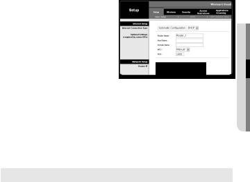
1.From the Setup menu of the Broadband Router, select <Applications & Gaming> - <Port Range Forward>. For setting the port range forward for
a third-party Broadband Router, refer to the user guide of that Broadband Router.
2.Select <TCP> and <UDP Port> for each connected camera to the Broadband Router.
Each port number for the Broadband Router should match that specified in <Setup> - <Network> - <Port> from the camera’s web viewer menu.
3.When done, click [Save Settings]. Your settings will be saved.
MM`` Above sample instructions are based on the CISCO’s Broadband Router.
`` The settings may differ depending on the connected Broadband Router model. For more information, refer to the user manual of the applicable router.
30_ network connection and setup
 Loading...