


NETWORK CAMERA
User Manual
SNV-6084

Network Camera
User Manual
Copyright
©2014 Samsung Techwin Co., Ltd. All rights reserved.
Trademark
 is the registered logo of Samsung Techwin Co., Ltd. The name of this product is the registered trademark of Samsung Techwin Co., Ltd.
Other trademarks mentioned in this manual are the registered trademark of their respective company.
Restriction
Samsung Techwin Co., Ltd shall reserve the copyright of this document. Under no circumstances, this document shall be reproduced, distributed or changed, partially or wholly, without formal authorization of Samsung Techwin.
Disclaimer
Samsung Techwin makes the best to verify the integrity and correctness of the contents in this document, but no formal guarantee shall be provided. Use of this document and the subsequent results shall be entirely on the user’s own responsibility. Samsung Techwin reserves the right to change the contents of this document without prior notice.
Design and specifications are subject to change without prior notice.
The default password can be exposed to a hacking thread so it is recommended to change the password after installing the product.
Note that the security and other related issues caused by the unchanged password shall be responsible for the user.
overview
Important Safety Instructions
1. |
Read these instructions. |
|
|
2. |
Keep these instructions. |
|
|
3. |
Heed all warnings. |
● |
|
4. |
Follow all instructions. |
overview |
|
|
|
||
5. |
Do not use this apparatus near water. |
|
|
6. |
Clean only with dry cloth. |
|
|
7. |
Do not block any ventilation openings, Install in accordance with the manufacturer’s |
|
|
8. |
instructions. |
|
|
Do not install near any heat sources such as radiators, heat registers, stoves, or other |
|
|
|
9. |
apparatus (including amplifiers) that produce heat. |
|
|
Do not defeat the safety purpose of the polarized or grounding-type plug. A polarized |
|
|
|
|
plug has two blades with one wider than the other. A grounding type plug has two |
|
|
|
blades and a third grounding prong. The wide blade or the third prong are provided for |
|
|
|
your safety. If the provided plug does not fit into your outlet, consult an electrician for |
|
|
10. |
replacement of the obsolete outlet. |
|
|
Protect the power cord from being walked on or pinched particularly at plugs, |
|
|
|
11. |
convenience receptacles, and the point where they exit from the apparatus. |
|
|
Only use attachments/ accessories specified by the manufacturer. |
|
|
|
12. |
Use only with the cart, stand, tripod, bracket, or table specified by |
|
|
|
the manufacturer, or sold with the apparatus. When a cart is used, |
|
|
|
use caution when moving the cart/apparatus combination to avoid |
|
|
13. |
injury from tip-over. |
|
|
Unplug this apparatus during lighting storms or when unused for |
|
|
|
14. |
long periods of time. |
|
|
Refer all servicing to qualified service personnel. Servicing is required when the |
|
|
|
|
apparatus has been damaged in any way, such as power-supply cord or plug is |
|
|
|
damaged, liquid has been spilled or objects have fallen into the apparatus, the apparatus |
|
|
|
has been exposed to rain or moisture, does not operate normally, or has been dropped. |
|
|
English _3
overview
WARNING
TO REDUCE THE RISK OF FIRE OR ELECTRIC SHOCK, DO NOT EXPOSE THIS PRODUCT TO RAIN OR MOISTURE. DO NOT INSERT ANY METALLIC OBJECT THROUGH THE VENTILATION GRILLS OR OTHER OPENNINGS ON THE EQUIPMENT.
Apparatus shall not be exposed to dripping or splashing and that no objects filled with liquids, such as vases, shall be placed on the apparatus.
To prevent injury, this apparatus must be securely attached to the Wall/ceiling in accordance with the installation instructions.
CAUTION
CAUTION
RISK OF ELECTRIC SHOCK.
DO NOT OPEN
CAUTION : TO REDUCE THE RISK OF ELECTRIC SHOCK.
DO NOT REMOVE COVER (OR BACK).
NO USER SERVICEABLE PARTS INSIDE.
REFER SERVICING TO QUALIFIED SERVICE PERSONNEL.
EXPLANATION OF GRAPHICAL SYMBOLS
The lightning flash with arrowhead symbol, within an equilateral triangle, is intended to alert the user to the presence of “dangerous voltage” within the product’s enclosure that may be of sufficient magnitude to constitute a risk of electric shock to persons.
The exclamation point within an equilateral triangle is intended to alert the user to the presence of important operating
and maintenance (servicing) instructions in the literature accompanying the product.
4_ overview

Class  construction
An apparatus with CLASS construction shall be connected to a MAINS socket outlet with a protective earthing connection.
Battery
Batteries(battery pack or batteries installed) shall not be exposed to excessive heat such as sunshine, fire or the like.
Disconnection Device
Disconnect the main plug from the apparatus, if it’s defected. And please call a repair man in your location.
When used outside of the U.S., it may be used HAR code with fittings of an approved agency is employed.
CAUTION
Risk of explosion if battery is replaced by an incorrect type. Dispose of used batteries according to the instructions.
These servicing instructions are for use by qualified service personnel only. To reduce the risk of electric shock do not perform any servicing other than that contained in the operating instructions unless you are qualified to do so.
The CVBS out terminal of the product is provided for easier installation, and is not recommended for monitoring purposes.
Please use the input power with just one camera and other devices must not be connected.
The ITE is to be connected only to PoE networks without routing to the outside plant.
overview ●
English _5

overview
Please read the following recommended safety precautions carefully.
yyDo not place this apparatus on an uneven surface.
yyDo not install on a surface where it is exposed to direct sunlight, near heating equipment or heavy cold area.
yyDo not place this apparatus near conductive material. yyDo not attempt to service this apparatus yourself. yyDo not place a glass of water on the product.
yyDo not install near any magnetic sources. yyDo not block any ventilation openings. yyDo not place heavy items on the product.
User’s Manual is a guidance book for how to use the products. The meaning of the symbols are shown below.
yyReference : In case of providing information for helping of product’s usages
yyNotice : If there’s any possibility to occur any damages for the goods and human caused by not following the instruction
Please read this manual for the safety before using of goods and keep it in the safe place.
6_ overview

CONTENTS
overview |
9 |
Product Features |
3 |
3 |
Important Safety Instructions |
10 |
Recommended PC Specifications |
|
10 |
Recommended Micro SD/ |
|
|
SDHC/SDXC Memory Card |
|
|
11 |
Specifications |
|
What’s Included |
|
|
13 |
At a Glance |
installation & connection
16
network connection and setup
34
16 |
Installation |
25 |
Inserting/Removing a Micro SD |
27 |
Memory Card |
Memory Card Information |
|
28 |
(Not Included) |
Connecting with other Device |
|
34 |
Connecting the Camera Directly |
35 |
to Local Area Networking |
Connecting the Camera Directly |
|
|
to a DHCP Based DSL/Cable |
36 |
Modem |
Connecting the Camera Directly |
|
37 |
to a PPPoE Modem |
Connecting the Camera to a |
|
|
Broadband Router with the |
38 |
PPPoE/Cable Modem |
Buttons used in IP Installer |
|
39 |
Static IP Setup |
43 |
Dynamic IP Setup |
44 |
Port Range Forward (Port Mapping) |
46 |
Setup |
Connecting to the Camera from a |
|
46 |
Shared Local PC |
Connecting to the Camera from a |
Remote PC via the Internet
overview ●
English _7

overview
web viewer |
49 |
Login |
47 |
47 |
Connecting to the Camera |
50 |
Installing Silverlight Runtime |
|
53 |
Installing STW WebViewer Plugin |
|
55 |
Using the Live Screen |
|
setup screen |
58 |
Playing the recorded video |
64 |
Video & Audio Setup |
|
64 |
64 |
Setup |
79 |
Network Setup |
|
90 |
Event Setup |
|
106 |
System Setup |
|
appendix |
119 |
Product Overview |
114 |
114 |
Specification |
120 |
Troubleshooting |
|
122 |
Open Source Announcement |
8_ overview

Product Features
•• Dustproof/Waterproof (IP66)
The dustproof and waterproof design makes you feel at ease when installing the product outdoors or exposing it to rain.
•• Full HD Video Quality
•• Multi-Streaming
This network camera can display videos in different resolutions and qualities simultaneously using different CODECs.
•• Web Browser-based Monitoring
Using the Internet web browser to display the image in a local network environment.
•• Alarm
If an event occurs, the event-related video will be transferred to the FTP/email specified by the user or saved to the Micro SD memory, or the event signal will be sent to the Alarm Out port.
•• Tampering Detection
Detects tempering attempts on video monitoring.
•• Motion Detection
Detects motion from the camera’s video input.
•• Intelligent Video Analysis
Analyzes video to detect logical events of specified conditions from the camera’s video input.
•• Face Detection
Detects faces from the camera’s video input.
•• Audio Detection
Detects sound louder than a certain level specified by user.
•• Auto Detection of Disconnected Network
Detects network disconnection before triggering an event.
•• ONVIF Compliance
This product supports ONVIF Profile-S.
For more information, refer to www.onvif.org.
overview ●
English _9

overview
Recommended PC Specifications
•• CPU : Intel Core 2 Duo 2.4 GHz or higher (for using 1920x1080 30 fps) Intel Core i7 2.8 GHz or higher (for using 1920x1080 60 fps)
`` Web Plug-in is optimized to SSE 4.1 Instruction Set.
•• Resolution : 1280X1024 pixels or higher (32 bit color)
•• RAM : 2GB or higher
•• Supported OS : Windows XP / VISTA / 7, MAC OS X 10.7
•• Supported Browser : Microsoft Internet Explorer (Ver. 10 ~ 7) Mozilla Firefox (Ver. 19 ~9) Windows Only
Google Chrome 15.0 (Ver. 25 ~ 15) Windows Only
Apple Safari (Ver. 6.0.2(Mac OS X 10.8, 10.7 only), 5.1.7) Mac OS X only
`` Windows 8 is supported only in the Desktop mode.
`` Neither a beta test version unlike the version released in the company website nor the developer version will be supported.
`` For IPv6 connection, Window 7 or higher is recommended. `` For Mac OS X, only the Safari browser is supported.
•• Video Memory : 256MB or higher
JJ``
``
If the driver of the video graphic adapter is not installed properly or is not the latest version, the video may not be played properly.
For a multi-monitoring system involving at least 2 monitors, the playback performance can be deteriorated depending on the system.
Recommended Micro SD/SDHC/SDXC Memory Card
Specifications
•• 4GB ~ 64GB
•• For your camera, we recommend you use a memory card from the following manufacturers: Micro SD/SDHC/SDXC Memory Card : Sandisk, Transcend
•• For the framerate below 30 fps, it is recommended to use the specification memory card of Class 6 or higher.
•• For the framerate over 31 fps, it is recommended to use the specification memory card of Class 10 UHS or higher.
10_ overview
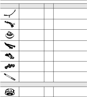
What’s Included
Please check if your camera and accessories are all included in the product package.
Appearance |
Item Name |
Quantity |
Description |
|
Camera |
1 |
|
|
Instruction book, |
2 |
|
|
Installer S/W CD, |
|
|
|
CMS S/W DVD |
|
|
|
Quick Guide |
1 |
|
|
(Optional) |
|
|
|
|
|
|
|
Warranty card |
1 |
|
|
(Optional) |
|
|
|
|
|
|
|
Cable for the testing monitor |
1 |
Used to test the camera connection to a |
|
portable display device |
||
|
|
|
|
|
Power Terminal Block |
1 |
Plugged in the power plug |
|
Template |
1 |
Product installation guide |
|
L Wrench |
1 |
Use the L-Wrench when detaching or |
|
attaching the dome cover |
||
|
|
|
overview ●
English _11
overview
Appearance |
Item Name |
Quantity |
Description |
|
Power Cable |
1 |
Used to plug into the power port |
|
Audio/alarm cable |
1 |
Used to connect with the |
|
audio and alarm port |
||
|
|
|
|
|
Cable bush |
1 |
Used to connect the LAN cable with a |
|
diameter of Ø7~8.5. |
||
|
|
|
|
|
Tapping Screw |
3 |
Used for installation on the |
|
wall or ceiling |
||
|
|
|
|
|
Plastic Anchor |
3 |
For fixing a screw, |
|
Inserted in a hole |
||
|
|
|
(reinforced anchoring force) |
|
Machine Screws |
3 |
Used for assembling the dome case when |
|
installing the product on the pipe, wall mount, |
||
|
|
|
etc. or blocking a hole. |
|
Drill bit |
1 |
Use the L-Wrench when detaching or |
|
attaching the dome cover, or installing the |
||
|
Options (not included) |
camera |
|
|
|
||
|
Indoor Buried Housing |
|
Housing for installing indoor buried type |
|
|
cameras |
|
|
|
|
|
12_ overview
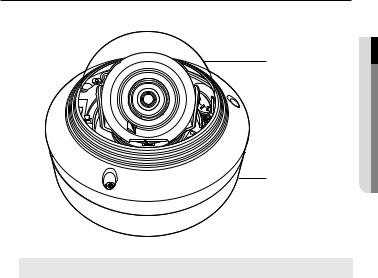
At a Glance
Appearance
a
b |
Item |
Description |
a Dome cover |
Case cover used to protect the lens and the main unit. |
b Camera Case |
Housing part that covers the camera body. |
overview ●
English _13
overview
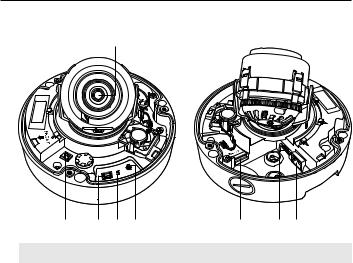
Components
a
AC
|
+ |
- |
24V/ |
|
|
DC |
12V |
T |
|
F |
|
RESET |
N |
VIDEO |
W |
|
|
AF |
b c d e |
f gh |
Item |
Description |
a Lens |
Lens for the camera. |
|
|
b Power Port |
Port for power terminal block. |
|
|
c Test Monitor Out |
Output port for test monitoring the video output. Use the test monitor cable |
to connect to a mobile display and check the test video. |
|
|
The button restores all camera settings to the factory default. |
|
Press and hold for about 5 seconds to reboot the system. |
d Reset Button |
J If you reset the camera, the network settings will be adjusted so that |
DHCP can be enabled. If there is no DHCP server in the network, you |
|
|
must run the IP Installer program to change the basic network settings |
|
such as IP address, Subnet mask, Gateway, etc., before you can |
|
connect to the network. |
14_ overview

Item |
|
Description |
|
|
T |
Zoom in (Tele) |
|
e ButtonZoom/Focus Control |
W |
Zoom out (Wide) |
|
N |
Focusing on a near object (Near) |
||
|
F |
Focusing on a far object (Far) |
|
|
Focus Control |
Press this button for automatic focus control. |
|
Micro SD Memory |
Compartment for the Micro SD memory card. |
|
|
f Card Compartment |
|||
g Audio and alarm |
Plug in the audio and alarm cable to this port to connect with external alarm |
||
cable port |
device/microphone/speaker. |
|
|
h Network Port |
Used to connect the PoE or Ethernet cable for network connection. |
||
|
|
|
|
overview ●
English _15
installation & connection
Precautions before installation
Ensure you read out the following instructions before installing the camera:
•• It must be installed on the area (ceiling or wall) that can withstand 5 times the weight of the camera including the installation bracket.
•• Stuck-in or peeled-off cables can cause damage to the product or a fire.
•• For safety purposes, keep anyone else away from the installation site. And put aside personal belongings from the site, just in case.
Installation
JJ`` This camera is waterproof and in compliance with the IP66 spec, but the jack connected to the external cable is not. You are recommended to install this product below the edge of eaves to prevent the cable from being externally exposed.
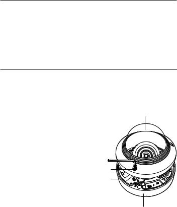
Disassembling
1. With the provided L-wrench and |
Dome cover |
drill bit, loosen 3 bolts on the dome |
|
cover counter clockwise to remove |
|
the cover. |
|
Bolts
Camera Body
AC24V/DC

 12V
12V
VIDEO
 RESET
RESET
T
F
N |
W |
AF
Camera Case
16_ installation & connection
Installation |
|
|
|
1. |
Drill a hole (diameter : 6mm, depth : min |
|
|
|
55mm) of the case bottom and insert the |
|
|
2. |
provided plastic anchor to the end. |
12V |
DC/24V |
Fit the bottom hole to the anchor hole and |
|
|
|
|
insert and fix the taping screw (M4.5xL50). |
|
|
3.Connect and arrange the necessary cables 


 lest that they should be damaged or twisted


 while installing the camera.
4.Adjust the lens in a desired direction by
referring to the “Adjusting the monitoring direction for the camera" section. (page 24)
5.Close the dome cover.
`` To ensure waterproofing, tight up the fixing bolts using the L-wrench and drill bit.
connectionin&sta●ationll
English _17

installation & connection
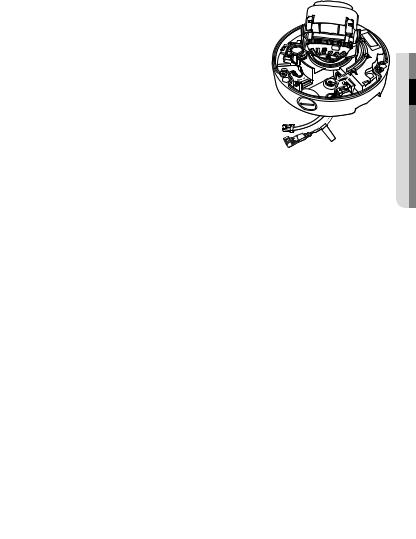
Connecting waterproof power cable and LAN cable
1.Remove the dome cover and the case.
2.Pull out the long projected part of the rubber plug on the bottom and remove it as shown in the figure.
JJ`` Use an appropriate cable bush for the LAN cable to be connected.
-- Basic camera : Use the cable with a diameter of Ø5~6.5.
-- Components provided : Use the cable with a diameter of Ø7~8.5.
3.Insert the power cable into the small hole made by removing the projected part of the rubber plug in step 2 above, and lay the cable along the long groove.
4. Connect the power cable with the power terminal block.
ofRatedCAUTION: the
VoltageBe power ware and of connection Polaritythe .
18_ installation & connection
5. Insert the LAN cable into the large hole made by removing the projected part of the rubber plug in step 2 above.
6. Remove the sheath with a cable cutter, and align the cables.
7. Connect the LAN cable with a LAN connector, and insert it into the LAN tool.
8. Connect the finished cable to the Ethernet port.
ofRatedCAUTION: the
VoltageBe power ware and of connection Polaritythe .
connectionin&sta●ationll
English _19

installation & connection
Connecting alarm cable
1.Remove the dome cover and the case.
2.Pull out the rubber plug on the bottom as shown in the figure.
3.Insert the alarm cable into the hole made by removing the rubber plug in step 2, and connect the cable with the PCB alarm terminal.
4. Align the cable so that it should not be damaged or jammed when installing the camera.
5. Put the rubber plug of the alarm cable into the hole.
6. Adjust the lens in a desired direction by referring to the “Adjusting the monitoring direction for the camera” section. (page 24)
7. Attach the dome cover.
20_ installation & connection
Attaching to the unbundled adapter
Choose and purchase a necessary one of the following options (unbundled) that is suitable to the installation site or for your convenience.
1. Remove the dome cover from the case by referring to the “Disassembling” section. (page 16)
2. Use the provided machine screw to fix the camera case to the unbundled adapter.
3.Connect and arrange the necessary cables lest that they should be damaged or twisted while installing the camera.
4.Install the camera body in the reverse order of “Disassembling”.
5.Adjust the lens in a desired direction by referring to the “Adjusting the monitoring direction for the camera” section. (page 24)
6.Close the dome cover.
`` To ensure waterproofing, tight up the fixing bolts using the L-wrench and drill bit.
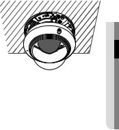
Outdoor installation
When you install it outside of the building, please waterproof it with waterproof butyl rubber |
|||||||||||
tape (can be purchased in stores) so that water does not leak from the gap of the cable |
|||||||||||
connected to the outside. |
|
|
|
|
|
|
|
|
|
|
|
1. Connect the power, I/O, BNC, and LAN |
|
|
|
|
|
|
|
|
|
|
|
|
Camera |
|
|
|
|
|
|
|
|
System |
|
cables. |
|
|
|
|
|
|
|
|
|
|
|
2. Wrap the black cable jacket (Area A) and the |
|
|
|
|
|
|
|
|
|
|
|
|
|
|
|
|
|
|
|
|
|
||
cable connection area with waterproof (butyl |
|
|
|
|
|
|
|
|
|
|
|
Camera |
|
|
|
|
|
|
|
|
System |
||
rubber) tape so that more than half of the |
|
|
|
|
|
|
|
|
|
|
|
|
|
|
|
|
|
|
|
|
|
||
butyl rubber tape is overlapped. |
|
A |
|
|
|
|
|
|
A |
||
|
|
|
|
|
|
|
|
|
|
|
|
JJ`` If the cable jacket is not waterproofed properly, |
Camera |
|
|
|
|
|
|
|
|
System |
|
|
|
|
|
|
|
|
|
|
|
||
|
|
|
|
|
|
|
|
|
|
||
then it can directly cause leakage. Make sure to |
|
|
|
|
|
|
|
|
|
|
|
protect the cable with a dense layer of taping. |
|
|
|
|
|
|
|
|
|
|
|
`` Waterproof butyl tape is made of butyl rubber that can be stretched to twice its normal length. |
|||||||||||
connectionin&sta●ationll
English _21
installation & connection
Optional Accessories for Installation
For your easier installation, you can purchase appropriate optional accessories available.
1. WALL MOUNT ADAPTOR(SBP-300WM or SBP-300WM1)/HANGING MOUNT (SBP-301HM3)
This adaptor is used when installing the dome camera onto a wall.
2.CEILING MOUNT ADAPTOR(SBP-300CM)/ HANGING MOUNT(SBP-301HM3)
This adaptor is used when installing the dome camera on a concrete ceiling.
22_ installation & connection
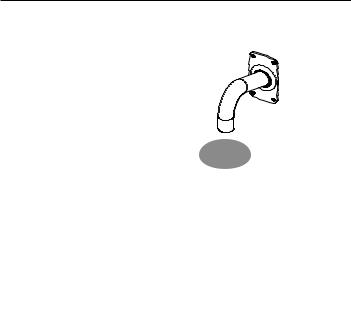
3.POLE MOUNT ADAPTOR(SBP-300PM)
This is an adaptor for WALL MOUNT ADAPTOR (SBP-300WM or SBP-300WM1) installation on a pole whose diameter is bigger than 80mm.
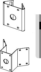
4.CORNER MOUNT ADAPTOR (SBP-300KM) This is an adaptor for WALL MOUNT ADAPTOR (SBP-300WM or SBP-300WM1) installation on the corner of wall joint.
connectionin&sta●ationll
English _23

installation & connection
Adjusting the monitoring direction for the camera
Pan
AF
W |
N |
F
T
RESET 
 VIDEO
VIDEO
|
12V |
DC/ |
- |
|
24VAC |
+ |
|
Tilt
Lens rotation
`` Adjusting the monitoring direction
You can adjust the camera direction only when the camera is fixed on the ceiling. Where, rotating the camera unit to the left or right is called Pan, adjusting the tilt is called Tilt, and turning the lens on its axis is called Rotation.
-- The effective range of pan is a total of 354 degrees.
-- The effective range of rotation is a total of 355 degrees. -- The effective range of tilt is a total of 67 degrees.
JJ `` |
The image can be covered up by the camera case depending on the angle. |
`` |
Do not forcefully turn the focus/zoom lens after the dome case is disassembled. |
|
Otherwise, it may cause an incorrect focus due to a motor failure. |
`` Methods of adjustment
1.After installing the camera, adjust the panning angle in consideration of the monitoring direction.
2.Set the horizontal angle so that the image is not reversed.
3.Adjust the tilt angle so that the camera faces toward the monitoring object.
24_ installation & connection
Inserting/Removing a Micro SD Memory Card
JJ`` Disconnect the power cable from the camera before inserting the Micro SD memory card.
`` Do not insert the Micro SD memory card while it’s upside down by force. Otherwise, it may damage the Micro SD memory card.
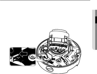
Inserting a Micro SD Memory Card
Push the Micro SD memory card in the direction of the arrow shown in the diagram.
connectionin&sta●ationll
English _25
installation & connection
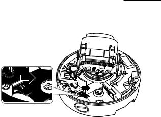
Removing a Micro SD Memory Card
Gently press down on the exposed end of the memory card as shown in the diagram to eject the memory card from the slot.
JJ`` Pressing too hard on the Micro SD memory card can cause the card to shoot out uncontrollably from the slot when released.
`` To pull out the micro SD memory card, turn off the camera power or set the device to <Off> of <Storage> and press the [Apply ( )] button. (Page 91)
`` If you turn off the camera or remove the Micro SD memory card that contains data from the product, the data may be lost or damaged.
26_ installation & connection
Memory Card Information (Not Included)
What is a memory card?
The memory card is an external data storage device that has been developed to offer an entirely new way to record and share video, audio, and text data using digital devices.
Selecting a memory card that’s suitable for you
Your camera supports Micro SD/SDHC/SDXC memory cards.
You may, however, experience compatibility issues depending on the model and make of the memory card.
For your camera, we recommend you use a memory card from the following manufacturers:
Micro SD/SDHC/SDXC Memory Card : Sandisk, Transcend
Memory cards of 4GB ~ 64GB is recommended for using with this camera.
Playback performance can be affected depending on the speed of memory card, so use the high-speed memory card.
For the framerate below 30 fps, it is recommended to use the specification memory card of Class 6 or higher.
For the framerate over 31 fps, it is recommended to use the specification memory card of Class 10 UHS or higher.
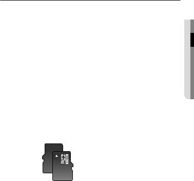
Memory Card Components
Contacts 


Micro SD/SDHC/SDXC
connectionin&sta●ationll
English _27

installation & connection
Connecting with other Device
+ |
- |
AC |
|
24V/ |
|
DC |
|
12V |
|
Monitor to install
T
F
|
RESET |
N |
VIDEO |
W |
|
|
AF |
Ethernet
Power 

ofRatedCAUTION: the
VoltageBe power
ware and connec of
Polaritythe tion .
JJ`` The CVBS out terminal of the product is provided for easier installation, and is not recommended for monitoring purposes.
28_ installation & connection

Ethernet Connection
Connect the Ethernet cable to the local network or to the Internet.
Power Supply
Use the screwdriver to connect each line (+, –) of the power cable to the corresponding power port of the camera.
JJ`` When connecting PoE and DC 12V, or PoE and AC 24V at the same time, the unit starts operation with the first connected power.
-- You can also use a router featuring PoE to supply power to the camera.
-- Use PoE that is compliant with the IEEE 802.3af protocols.
`` The heater operates at a low temperature environment in all cases that the dome camera is operated by PoE, AC 24V or DC 12V.
-- Install the product at the temperature of -35°C or higher.
-- The product can be operated down to the temperature of -40°C after it started up. `` Be careful not to reverse the polarity when you connect the power cable.
`` AC 24V can be connected in non-polar union.
`` If you want to connect an external device, you must turn off the external device before proceeding.
connectionin&sta●ationll
English _29

installation & connection
Power Cable Specification for Each Model
In case of DC 12V Input: |
|
|
|
|
|
|
Wire Type (AWG) |
|
#22 |
|
#20 |
#18 |
|
Cable Length (Max.) |
|
24m |
|
38m |
60m |
|
In case of AC 24V Input: |
|
|
|
|
|
|
Wire Type (AWG) |
|
#22 |
|
#20 |
#18 |
|
Cable Length (Max.) |
|
34m |
|
55m |
88m |
|
Network Cable Specification |
|
|
|
|||
Item |
|
Contents |
|
|
Remark |
|
Connector |
|
RJ45 |
|
|
|
|
Ethernet |
|
10/100Base-T |
|
|
10/100 Mbps |
|
Cable |
|
UTP Category 5e |
|
|
|
|
Max Distance |
|
100M |
|
|
|
|
PoE Support |
|
IEEE 802.3af |
|
|
|
|
30_ installation & connection
 Loading...