


SNV-7080R

NETWORK CAMERA
User Manual
SNV-7080R

Copyright
©2011 Samsung Techwin Co., Ltd. All rights reserved.
Trademark
is the registered logo of Samsung Techwin Co., Ltd.
The name of this product is the registered trademark of Samsung Techwin Co., Ltd.
Other trademarks mentioned in this manual are the registered trademark of their respective company.
Restriction
Samsung Techwin Co., Ltd shall reserve the copyright of this document. Under no circumstances, this
document shall be reproduced, distributed or changed, partially or wholly, without formal authorization of
Samsung Techwin.
Disclaimer
Samsung Techwin makes the best to verify the integrity and correctness of the contents in this document, but
no formal guarantee shall be provided. Use of this document and the subsequent results shall be entirely on
the user’s own responsibility. Samsung Techwin reserves the right to change the contents of this document
without prior notice.
Warranty
If the product does not operate properly in normal conditions, please let us know. Samsung Techwin will resolve
the problem for free of charge. The warranty period is 3 years. However, the followings are excluded:
•
If the system behaves abnormally because you run a program irrelevant to the system operation.
•
Deteriorated performance or natural worn-out in process of time
❖
Design and specifications are subject to change without prior notice.
❖
The default password can be exposed to a hacking thread so it is recommended to change the
password after installing the product.
Note that the security and other related issues caused by the unchanged password shall be
responsible for the user.
Network Camera
User Manual
English _3
● OVERVIEW
IMPORTANT SAFETY INSTRUCTIONS
1. Read these instructions.
2. Keep these instructions.
3. Heed all warnings.
4. Follow all instructions.
5. Do not use this apparatus near water.
6. Clean only with dry cloth.
7. Do not block any ventilation openings, Install in accordance with the manufacturer’s
instructions.
8. Do not install near any heat sources such as radiators, heat registers, stoves, or other
apparatus (including amplifiers) that produce heat.
9. Do not defeat the safety purpose of the polarized or grounding-type plug. A polarized
plug has two blades with one wider than the other. A grounding type plug has two
blades and a third grounding prong. The wide blade or the third prong are provided for
your safety. If the provided plug does not fit into your outlet, consult an electrician for
replacement of the obsolete outlet.
10. Protect the power cord from being walked on or pinched particularly at plugs,
convenience receptacles, and the point where they exit from the apparatus.
11. Only use attachments/ accessories specified by the manufacturer.
12. Use only with the cart, stand, tripod, bracket, or table specified by
the manufacturer, or sold with the apparatus. When a cart is used,
use caution when moving the cart/apparatus combination to avoid
injury from tip-over.
13. Unplug this apparatus during lighting storms or when unused for
long periods of time.
14. Refer all servicing to qualified service personnel. Servicing is required when the
apparatus has been damaged in any way, such as power-supply cord or plug is
damaged, liquid has been spilled or objects have fallen into the apparatus, the apparatus
has been exposed to rain or moisture, does not operate normally, or has been dropped.
overview
overview
4_ overview
WARNING
TO REDUCE THE RISK OF FIRE OR ELECTRIC SHOCK, DO NOT EXPOSE
THIS PRODUCT TO RAIN OR MOISTURE. DO NOT INSERT ANY METALLIC
OBJECT THROUGH THE VENTILATION GRILLS OR OTHER OPENNINGS
ON THE EQUIPMENT.
Apparatus shall not be exposed to dripping or splashing and that no objects
filled with liquids, such as vases, shall be placed on the apparatus.
CAUTION
CAUTION
RISK OF ELECTRIC SHOCK.
DO NOT OPEN
CAUTION
: TO REDUCE THE RISK OF ELECTRIC SHOCK.
DO NOT REMOVE COVER (OR BACK).
NO USER SERVICEABLE PARTS INSIDE.
REFER SERVICING TO QUALIFIED SERVICE PERSONNEL.
EXPLANATION OF GRAPHICAL SYMBOLS
The lightning flash with arrowhead symbol, within an
equilateral triangle, is intended to alert the user to the
presence of “dangerous voltage” within the product’s
enclosure that may be of sufficient magnitude to constitute a
risk of electric shock to persons.
The exclamation point within an equilateral triangle is intended
to alert the user to the presence of important operating
and maintenance (servicing) instructions in the literature
accompanying the product.

English _5
● OVERVIEW
Class construction
An apparatus with CLASS construction shall be connected to a MAINS
socket outlet with a protective earthing connection.
Battery
Batteries(battery pack or batteries installed) shall not be exposed to excessive
heat such as sunshine, fire or the like.
Disconnection Device
Disconnect the main plug from the apparatus, if it’s defected. And please call
a repair man in your location.
When used outside of the U.S., it may be used HAR code with fittings of
an approved agency is employed.
CAUTION
These servicing instructions are for use by qualified service personnel only.
To reduce the risk of electric shock do not perform any servicing other than
that contained in the operating instructions unless you are qualified to do so.
The BNC Out terminal of the product is provided for easier installation, and is
not recommended for monitoring purposes.
If you keep the BNC cable connected, a risk of lightening may cause damage
or malfunction to the product.
Please use the input power with just one camera and other devices must not
be connected.

overview
6_ overview
Please read the following recommend safety precautions carefully.
Do not place this apparatus on an uneven surface.
Do not install on a surface where it is exposed to direct sunlight, near
heating equipment or heavy cold area.
Do not place this apparatus near conductive material.
Do not attempt to service this apparatus yourself.
Do not place a glass of water on the product.
Do not install near any magnetic sources.
Do not block any ventilation openings.
Do not place heavy items on the product.
User’s Manual is a guidance book for how to use the products.
The meaning of the symbols are shown below.
Reference : In case of providing information for helping of product’s usages
Notice : If there’s any possibility to occur any damages for the goods and
human caused by not following the instruction
Please read this manual for the safety before using of goods and keep it in
the safe place.

English _7
● OVERVIEW
CONTENTS
OVERVIEW
3
3 Important Safety Instructions
9 Product Features
10 Recomended PC Specifications
10 Recomended SD/SDHC Memory
Card Specifications
11 What’s Included
12 At a Glance
INSTALLATION &
CONNECTION
14
14 Installation
20 Inserting/Removing an SD
Memory Card
21 Memory Card Information
(Not Included)
22 Connecting with other Device
NETWORK CONNECTION
AND SETUP
25
25 Connecting the Camera Directly
to Local Area Networking
26 Connecting the Camera Directly
to a DHCP Based DSL/Cable
Modem
27 Connecting the Camera Directly
to a PPPoE Modem
28 Connecting the Camera to a
Broadband Router with the
PPPoE/Cable Modem
29 Buttons used in IP Installer
30 Static IP Setup
33 Dynamic IP Setup
34
Port Range Forward (Port Mapping)
Setup
36 Connecting to the Camera from a
Shared Local PC
36 Connecting to the Camera from a
Remote PC via the Internet

overview
8_ overview
SETUP SCREEN
47
47 Setup
47 Audio & Video Setup
58 Network Setup
64 Event Setup
70 System Setup
APPENDIX
75
75 Specification
79 Product Overview
81 Troubleshooting
83 Open Source Announcement
85 GPL/LGPL Software License
WEB VIEWER
37
37 Connecting to the Camera
38 Login
39 Installing ActiveX
40 Installing Silverlight Runtime
42 Using the Live Screen
45 Playback

English _9
● OVERVIEW
PRODUCT FEATURES
• Dustproof/Waterproof (IP66)
The dustproof and waterproof design makes you feel at ease when installing the product
outdoors or exposing it to rain.
• SSNR3 (Samsung Super Noise Reduction)
The
powerful DSP chip reduces the gain noise effectively to remove the time lag so that it
can provide a sharp and clear image in a low contrast scene.
• Day & Night (ICR)
It automatically detects the time change of the day to switch to a mode that is appropriate
to the current scene. In a daylight scene, it switches to the color mode for maintaining
the optimal color tones while it, at night, switches to B/W mode for identifying the low
contrast scene.
• IR mode
If the IR indicator turns on, the product switches to the IR mode for preventing an object
from being too bright, which helps you identify the object in near distance.
• Visibility:
25m
In B/W mode, the IR indicator turns on with the effective visibility of
25m at 0 Lux.
• SSDR (Samsung Super Dynamic Range)
For a scene showing a great contrast difference such as backlight scene, the product
maintains the bright areas while selectively making the dark areas brighter to balance the
overall contrast.
• Others
Other features include: HLC (High Light Compensation), SENS-UP, V-REV, H-REV,
D-ZOOM, SHARPNESS, Motion Detection, PRIVACY.
• Full HD Video Quality
• Multi-Streaming
This network camera can display videos in different resolutions and qualities
simultaneously using different CODECs.
• Web Browser-based Monitoring
Using the Internet web browser to display the image in a local network environment.
• Alarm
If an event occurs, the event-related video will be transferred to the email specified by the
user or the event signal will be sent to the Alarm Out port.

overview
10_ overview
• Video Motion Detection
Detects a motion from the video before triggering an event.
• Face Detection / Smart Codec
Recognizes a face from the camera input video, or transfers a clearer image of your specified area.
• Auto Detection of Disconnected Network
Detects network disconnection before triggering an event.
• ONVIF (Spec 1.02) Compliance
This product supports ONVIF Core Spec. 1.02.
For more information, refer to www.onvif.org.
RECOMENDED PC SPECIFICATIONS
• CPU : Intel Core 2 Duo 2.4GHz or higher
• Operating System : Windows XP, VISTA, 7
Mac OS
• Resolution : 1280X1024 pixels or higher
• RAM : 2GB or higher
• Web Browser : Internet Explorer 7.0 or higher, Firefox, Chrome, Safari
Neither a beta test version unlike the version released in the company website nor the developer version will
be supported.
On Firefox v3.5 or higher, displaying warning message dialog may cause an error.
If connecting to IPv6 in Windows XP, it can cause some problem.
It is recommended to connect to IPv6 in Windows 7.
• Video Memory : 256MB or higher
J
If the driver of the video graphic adapter is not installed properly or is not the latest version, the
video may not be played properly.
RECOMENDED SD/SDHC MEMORY CARD
SPECIFICATIONS
• 2GB ~ 32GB
• To ensure proper recording of video data, it is recommended you use a memory card that
supports at least read/write speed 10Mbps and Class 6.
English _11
● OVERVIEW
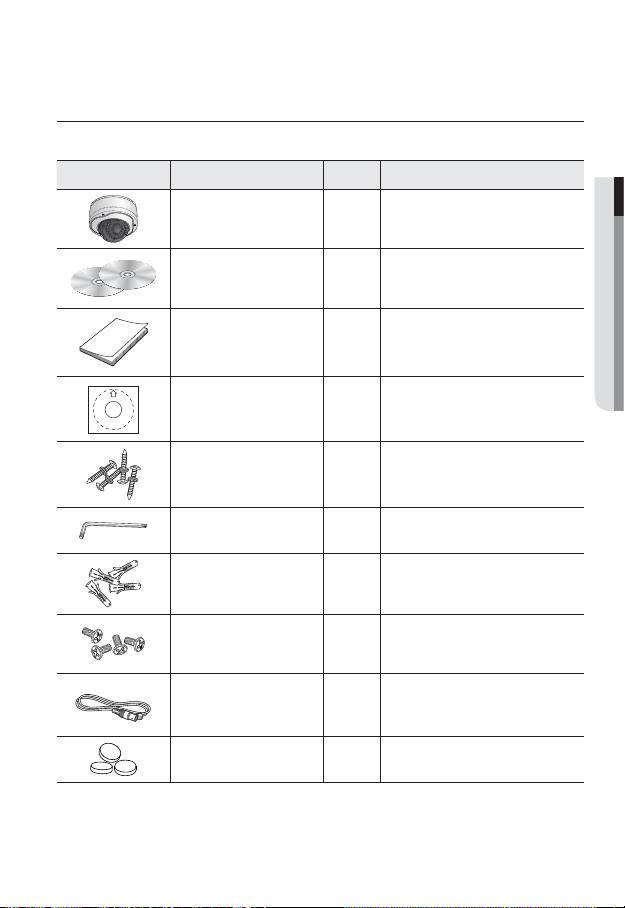
WHAT’S INCLUDED
Please check if your camera and accessories are all included in the product package.
Appearance Item Name Quantity Description
Camera 1
User Manual,
Installer S/W CD,
CMS S/W DVD
2
Quick Guide 1
Template 1 Product installation guide
ASSY-Tapping Screw 4 Used for installation on the wall or ceiling
L Wrench 1 Used to remove/fix the dome cover
Plastic Anchor 4
For fixing a screw, Inserted in a hole
(reinforced anchoring force)
Machine Screws 4
Used for assembling the dome case when
installing the product on the pipe, wall
mount, etc. or blocking a hole.
Cable for the testing monitor 1
Used to test the camera connection to a
portable display device
Rubber cap 3
Insulation cap for improved
EMC performance.
overview
12_ overview
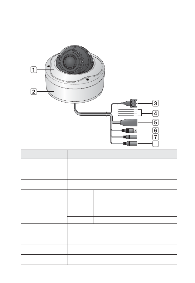
AT A GLANCE
Appearance
Item Description
Top cover Case cover used to protect the lens and the main unit.
b
Camera Case Covers the lens and camera body.
c
Power Port Used to plug the power cable.
Alarm In /
Out terminals
ARM-IN BLUE : Used to connect the alarm input signal.
ARM-OUT WHITE : Used to connect the alarm output signal.
A-COM
GRAY : Common port where the alarm output signal is
connected.
GND YELLOW : Used for earth-grounding.
Network Port Used to connect a PoE or LAN cable.
Video Out Port Analog video output port. (for installation)
Audio In Jack Used to connect to a microphone.
Audio Out Jack Used to connect to speakers.
8
English _13
● OVERVIEW
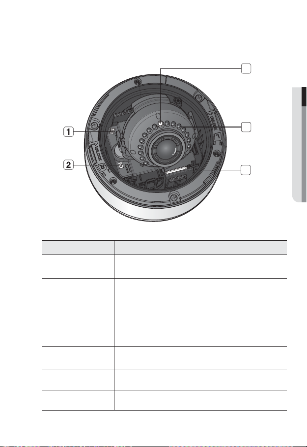
Inside
Item Description
Monitor Out
Using the test monitor cable, you can connect to a mobile display for camera
test. (for installation)
b
Reset Button
Resets the camera settings to the default. Press and hold it for about 5
seconds to turn off the system indicator and restart the system.
J
If you reset the camera, the network settings will be adjusted so that
DHCP can be enabled. If there is no DHCP server in the network, you
must run the IP Installer program to change the basic network settings
such as IP address, Subnet mask, Gateway, etc., before you can
connect to the network.
c
SD Memory Card
Compartment
Compartment for the SD memory card.
IR LED These infrared LED's are controlled by the illumination sensor.
Illumination Sensor Detects incoming light to control the IR LED.
3
4
5

14_ installation & connection
installation & connection
INSTALLATION
Precautions before installation
Ensure you read out the following instructions before installing the camera:
• Select an installation site (ceiling or wall) that can endure at least 5 times of the
camera weight.
• Stuck-in or peeled-off cables can cause damage to the product or a fire.
• For safety purposes, keep anyone else away from the installation site. And put aside
personal belongings from the site, just in case.
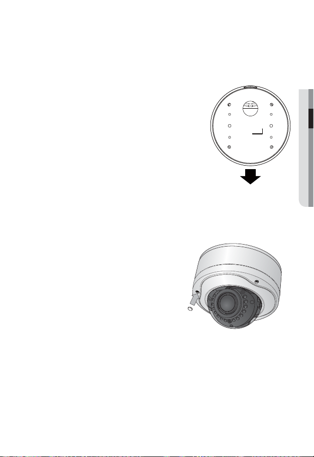
Disassembling
1. With the provided L-shaped
wrench, loosen 3 bolts on the top
cover counter clockwise to remove
the cover.
2.
Loosen 3 screws on the camera body
counter clockwise, and pull up the
left/right LOCKER lever (in the arrow
direction) to release the lock. Then,
remove the camera from the case.
LOCKER Lever
Bolts
Camera Case
Top cover
Camera Body
English _15
● INSTALLATION & CONNECTION
Installing on the ceiling directly
1. Remove the top cover from the case by referring to the “Disassembling” section.
(page 14)
2. Drill a hole (diameter: 5mm, depth: min 35mm) in a
desired position of the case bottom and insert the
provided plastic anchor (HUD 5) to the end.
3. Fit the bottom hole to the anchor hole and insert
and fix the ASSY taping screw (TH M4×L30).
When assembling the camera case to a junction box, select
appropriate screw holes on the case bottom for installation.
4. Connect and arrange the necessary cables lest that
they should be damaged or twisted while installing
the camera.
5. Install the camera body in the reverse order of
“Disassembling”.
6. Adjust the lens in a desired direction by referring to
the “Adjusting the monitoring direction for the camera" section. (page 19)
7. Close the top cover.
To ensure waterproofing, tight up the fixing bolts using the L-wrench.
For improved EMC performance, it is recommended to
use the insulation cap provided as an accessory. (x3)
CAMERA FRONT

installation & connection
16_ installation & connection
Ceiling mount
1. Remove the top cover from the case by
referring to the “Disassembling” section.
(page 14)
2. Use the provided template to drill one hole for
the camera, and one for the screw (5 mm in
diameter, at least 35 mm in depth), and insert
the plastic anchor (HUR 5) to the end of the
screw hole.
3. Connect and arrange the necessary cables
lest that they should be damaged or twisted
while installing the camera.
4. Loosen and remove the case-fixing screws on the camera unit. (x3)
5. Insert the camera unit into the hole so that it fits to the camera hole, and fix the unit
using the ASSY tapping screws (TH M4×L30). (x3)
6. Adjust the lens in a desired direction by referring to the “Adjusting the monitoring
direction for the camera" section. (page 19)
7. Close the top cover.
To ensure waterproofing, tight up the fixing bolts using the L-wrench.
English _17
● INSTALLATION & CONNECTION
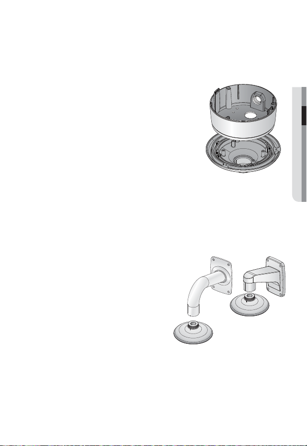
Attaching to the unbundled adapter
Choose and purchase a necessary one of the following options (unbundled) that is suitable
to the installation site or for your convenience.
1. Remove the top cover from the case by referring to
the “Disassembling” section. (page 14)
2. Use the provided machine screw to fix the camera
case to the unbundled adapter.
3. Connect and arrange the necessary cables lest that
they should be damaged or twisted while installing
the camera.
4. Install the camera body in the reverse order of
“Disassembling”.
5. Adjust the lens in a desired direction by referring
to the “Adjusting the monitoring direction for the
camera" section. (page 19)
6. Close the top cover.
To ensure waterproofing, tight up the fixing bolts using the L-wrench.
Optional Accessories for Installation
For your easier installation, you can purchase appropriate optional accessories available.
1. WALL MOUNT ADAPTOR(SBP-300WM or
SBP-300WM1)/HANGING MOUNT(SBP-
300HM1)
This adaptor is used when installing the
dome camera onto a wall.
installation & connection
18_ installation & connection
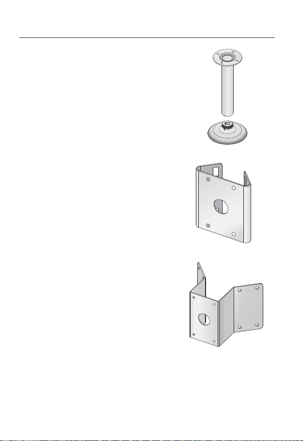
2. CEILING MOUNT ADAPTOR(SBP-300CM)/
HANGING MOUNT(SBP-300HM1)
This adaptor is used when installing the dome
camera on a concrete ceiling.
3. POLE MOUNT ADAPTOR(SBP-300PM)
This is an adaptor for WALL MOUNT ADAPTOR
(SBP-300WM or SBP-300WM1) installation on a
pole whose diameter is bigger than 80mm.
4. CORNER MOUNT ADAPTOR (SBP-300KM)
This is an adaptor for WALL MOUNT
ADAPTOR (SBP-300WM or SBP-300WM1)
installation on the corner of wall joint.
English _19
● INSTALLATION & CONNECTION
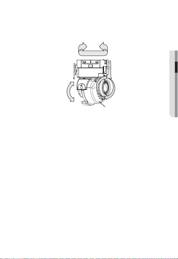
Adjusting the monitoring direction for the camera
❖
Adjusting the monitoring direction
You can adjust the camera direction only when the camera is fixed on the ceiling.
Where, rotating the camera unit to the left or right is called Pan, adjusting the tilt is called
Tilt, and turning the lens on its axis is called Rotate.
- The effective range of pan is a total of 355 degrees.
- The effective range of rotation is a total of 355 degrees.
- The effective range of tilt is a total of 90 degrees.
J
In some angles, the top cover may cause cutting some part of the monitoring object.
Do not rotate the focus/zoom lens by force after removing the cover front.
Otherwise, it may cause an incorrect focus due to a motor failure.
❖
Methods of adjustment
1. After installing the camera, adjust the panning angle in consideration of the
monitoring direction.
When tilting the camera, you should adjust the horizontal angle lest that the image
be displayed reversely.
2. Adjust the rotation angle to correct the image display position (up/down/left/right).
Rotating means rotation on the basis of the rear lens unit.
3. Adjust the tilt angle so that the camera faces toward the monitoring object.
Panning
Tilting
Lens rotation
Cover front
installation & connection
20_ installation & connection
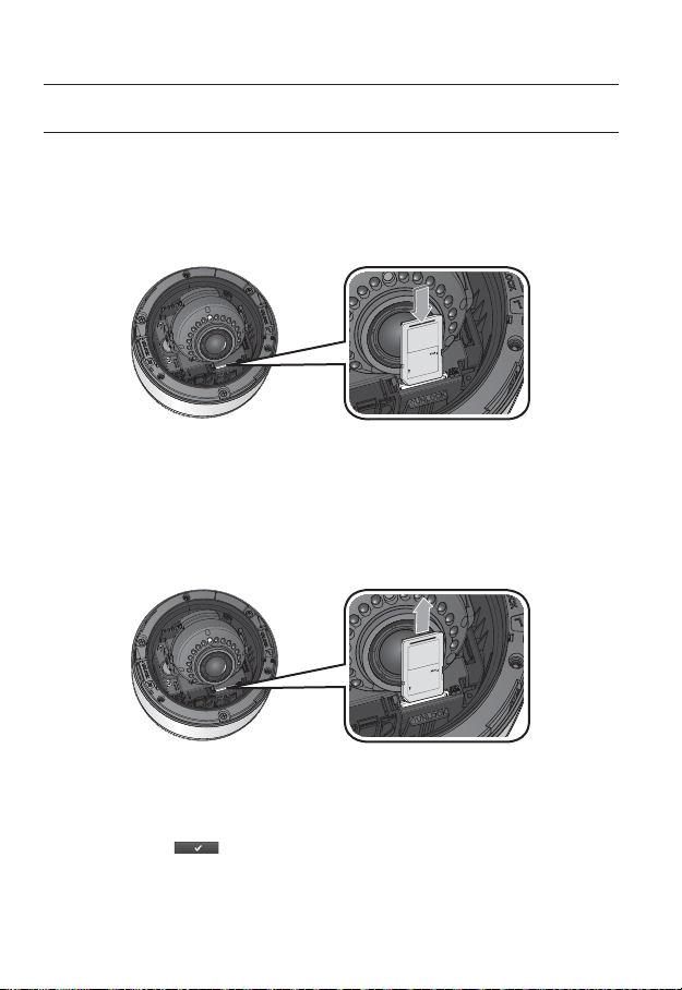
INSERTING/REMOVING AN SD MEMORY CARD
J
Disconnect the power cable from the camera before inserting the SD memory card.
Inserting an SD Memory Card
Push the SD memory card in the direction of the arrow shown in the diagram.
J
Do not insert the SD memory card while it’s upside down by force. Otherwise, it may damage the
SD memory card.
Removing an SD Memory Card
Gently press down on the exposed end of the memory card as shown in the diagram to
eject the memory card from the slot.
J
Pressing too hard on the SD memory card can cause the card to shoot out uncontrollably from the
slot when released.
To remove the SD memory card, set <Record> to <Off> from <SD record> and press
[Apply (
)]. (page 65)
If you have saved data in the SD memory card, removing the SD memory card prior to setting
record to OFF will cause damage to the data stored in the card.
English _21
● INSTALLATION & CONNECTION
MEMORY CARD INFORMATION (NOT INCLUDED)
What is a memory card?
The memory card is an external data storage device that has been developed to offer an
entirely new way to record and share video, audio, and text data using digital devices.
Selecting a memory card that’s suitable for you
Your camera supports SD/SDHC memory cards.
You may, however, experience compatibility issues depending on the model and make of
the memory card.
For your camera, we recommend you use a memory card from the following
manufacturers:
SD/SDHC Memory Card : Sandisk, Transcend, Kingston
Playback performance can be affected depending on the speed of memory card, so use
the high-speed memory card.
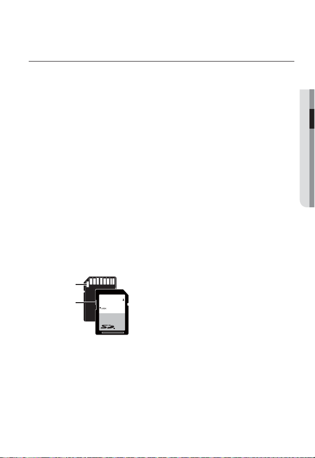
Memory Card Use
SD and SDHC memory cards feature a switch that disables writing data on to the media.
Having this switch to the Lock position will prevent accidental deletion of data stored in the
memory card but at the same time will also prevent you from writing data on to the media.
❖
Memory Card Components
SD/SDHC
Lock Switch
Contacts
installation & connection
22_ installation & connection
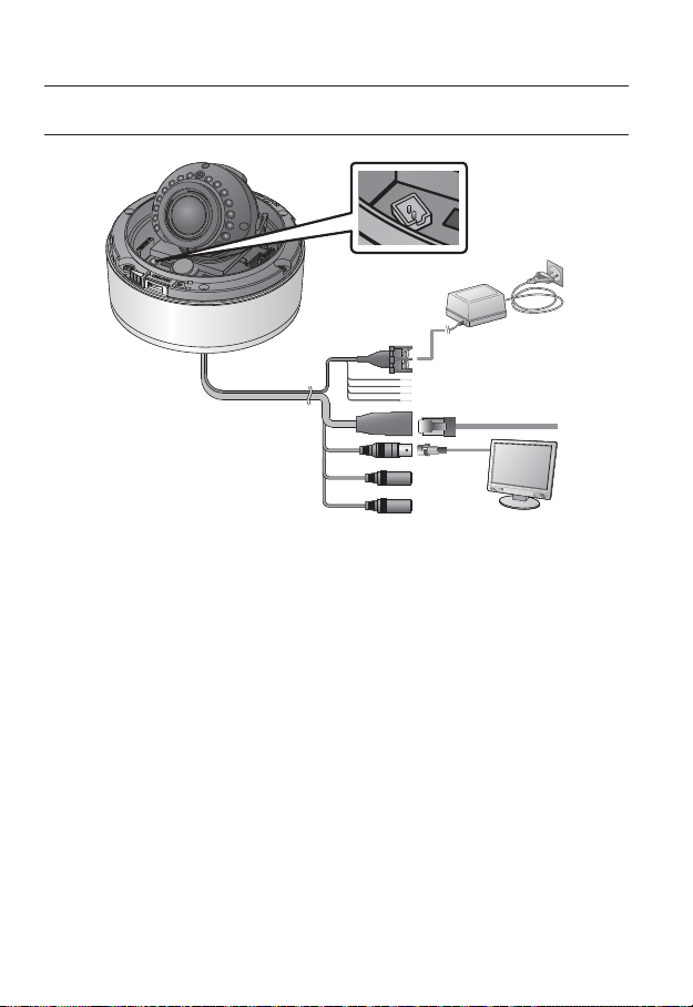
CONNECTING WITH OTHER DEVICE
Connecting to the monitor
Connect the video out port of the camera to the video input port of the monitor.
M
In the initial installation of the camera, you can connect the camera to the monitor for checking
the connection status.
You can set the video output type to either NTSC or PAL. (page 49).
J
The BNC Out terminal of the product is provided for easier installation, and is not recommended
for monitoring purposes.
If you keep the BNC cable connected, a risk of lightening may cause damage or malfunction to
the product.
Ethernet Connection
Connect the Ethernet cable to the local network or to the Internet.
Monitor
Power
Ethernet
Monitor Out
English _23
● INSTALLATION & CONNECTION
Power Supply
Use the screwdriver to connect each line (+, –) of the power cable to the corresponding
power port of the camera.
J
Be careful not to reverse the polarity when you connect the power cable.
You can also use a router featuring PoE (Power over Ethernet) to supply power to the camera.
The heater will operate properly only by the power source of AC 24V.
If using PoE, the heater will not operate at all.
Use an adaptor if the installation site requires heater operations. Adaptor is sold separately.
For the power specifications, refer to the “Appendix”. (page 78)
If PoE and DC 12V are both applied, this camera will get supplied with power from PoE.
Please make sure the monitor and camera are turned off when connecting them.
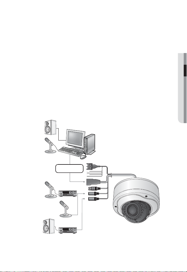
Connecting to Audio Input/Output
PC
Speaker
Microphone
Amp
Amp
Microphone
Microphone
Speaker
Network
installation & connection
24_ installation & connection
1. Connect the AUDIO IN port of the camera with the microphone directly or LINE OUT
port of the amplifier that the microphone is connected to.
2. Connect the AUDIO OUT port of the camera with the LINE IN port of the speaker.
3. Check the specifications for audio input.
• Audio Codec
G.711 PCM. μ-law 64kbps 8kHz sampling
• Full duplex Audio
• Audio in
Used for mono signal line input (Max.2.4 Vpp)
• Audio out
Used for mono signal line output (Max.2.4 Vpp)
• Line out impedance
600
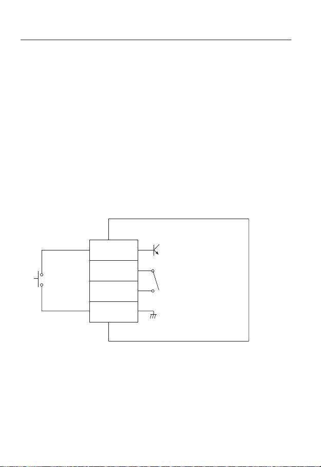
Alarm I/O Wiring Diagram
ARM-IN
ARM-OUT
A-COM
GND
(5mA sink)
(30VDC 2A,
125VAC 0.5A MAX)
English _25
●
NETWORK CONNECTION AND SETUP
You can set up the network settings according to your network configurations.
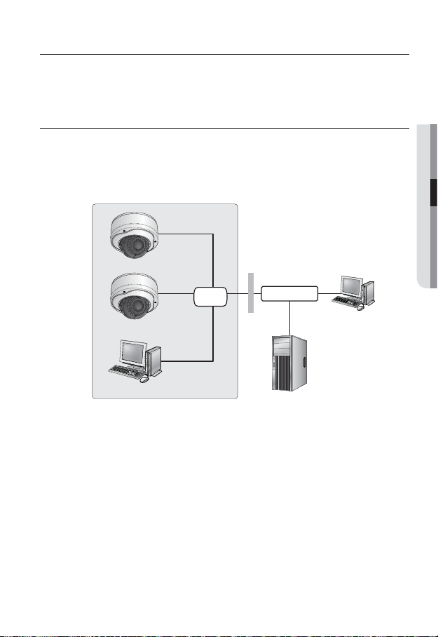
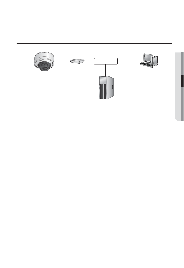
CONNECTING THE CAMERA DIRECTLY TO LOCAL AREA
NETWORKING
Connecting to the camera from a local PC in the LAN
1. Launch an Internet browser on the local PC.
2. Enter the IP address of the camera in the address bar of the browser.
M
A remote PC in an external Internet out of the LAN network may not be able to connect to the
camera installed in the intranet if the port-forwarding is not properly set or a firewall is set.
In this case, to resolve the problem, contact your network administrator.
By factory default, the IP address will be assigned from the DHCP server automatically. If there is
no DHCP server available, the IP address will be set to 192.168.1.100.
To change the IP address, use the IP Installer.
For further details on IP Installer use, refer to “Static IP Setup”. (Page 30)
network connection and setup
Switch
HUB
Camera
Camera
Local PC
Firewall
External Remote PC
DDNS Server
(Data Center, KOREA)
INTERNET
<Local Network>
26_ network connection and setup
network connection and setup
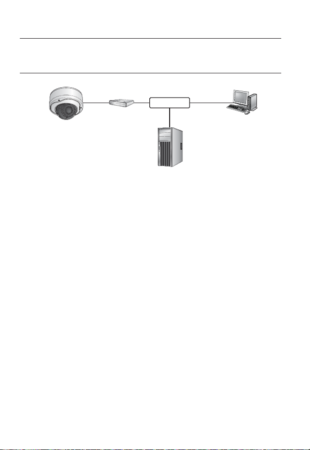
CONNECTING THE CAMERA DIRECTLY TO A DHCP
BASED DSL/CABLE MODEM
1. Use the cross LAN cable to connect the network cable directly to your PC.
2. Run the IP Installer and change the IP address of the camera so that you can use
the web browser on your desktop to connect to the Internet.
3. Use the Internet browser to connect to the camera.
4. Move to [Setup] page.
5. Move to [Network] – [DDNS] and configure the DDNS settings.
6. Move to [Network] – [Interface], and set the network type to [DHCP].
7. Connect the camera, which was removed from your PC, directly to the modem.
8. Restart the camera.
M
For registering the DDNS settings, refer to “Registering with DDNS”. (page 60)
For configuring the DDNS settings, refer to “DDNS”. (page 59)
For setting the network type, refer to “Interface”. (page 58)
Camera
External Remote PC
DDNS Server
(Data Center, KOREA)
DSL/Cable
Modem
INTERNET
English _27
●
NETWORK CONNECTION AND SETUP
CONNECTING THE CAMERA DIRECTLY TO A PPPoE
MODEM
1. Use the cross LAN cable to connect the network cable directly to your PC.
2. Run the IP Installer and change the IP address of the camera so that you can use
the web browser on your desktop to connect to the Internet.
3. Use the Internet browser to connect to the camera.
4. Move to [Setup] page.
5. Move to [Network] – [DDNS] and configure the DDNS settings.
6. Move to [Network] – [Interface], and set the network type to [PPPoE].
7. Connect the camera, which was removed from your PC, directly to the modem.
8. Restart the camera.
M
For registering the DDNS settings, refer to “Registering with DDNS”. (page 60)
For configuring the DDNS settings, refer to “DDNS”. (page 59)
For setting the network type, refer to “Interface”. (page 58)
Camera
External Remote PC
DDNS Server
(Data Center, KOREA)
PPPoE Modem
INTERNET
28_ network connection and setup
network connection and setup
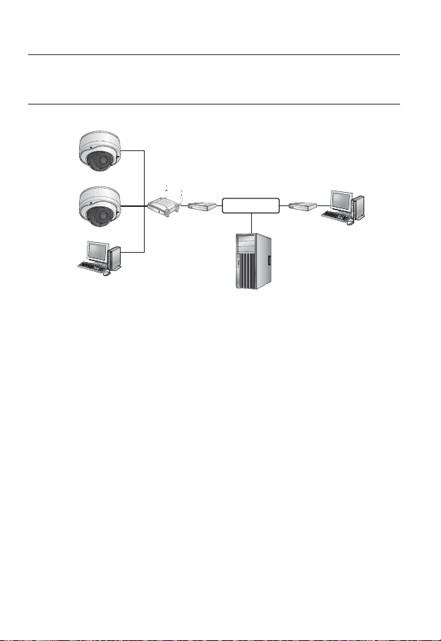
CONNECTING THE CAMERA TO A BROADBAND ROUTER
WITH THE PPPoE/CABLE MODEM
This is for a small network environment such as homes, SOHO and ordinary shops.
Configuring the network settings of the local PC connected to a
Broadband Router
Configuring the network settings of the local PC connected to a Broadband Router, follow
the instructions below.
• Select : <Network Neighborhood>
<Properties>
<Local Area Connection>
<Properties>
<General>
<Internet Protocol (TCP/IP)>
<Properties>
<Obtain an IP address automatically> or <Use the following IP address>.
• Follow the instructions below if you select <Use the following IP address>:
ex1) If the address (LAN IP) of the Broadband Router is 192.168.1.1
IP address : 192.168.1.100
Subnet Mask : 255.255.255.0
Default Gateway : 192.168.1.1
ex2) If the address (LAN IP) of the Broadband Router is 192.168.0.1
IP address : 192.168.0.100
Subnet Mask : 255.255.255.0
Default Gateway : 192.168.0.1
ex3) If the address (LAN IP) of the Broadband Router is 192.168.xxx.1
IP address : 192.168.xxx.100
Subnet Mask : 255.255.255.0
Default Gateway : 192.168.xxx.1
M
For the address of the Broadband Router, refer to the product’s documentation.
Refer to the “Port Range Forward (Port Mapping) Setup” section of the Broadband Router’s
documentation. (Page 34)
Camera
Camera
Local PC
Broadband
Router
PPPoE or
Cable Modem
PPPoE or
Cable Modem
External Remote
PC
DDNS Server
(Data Center, KOREA)
INTERNET
English _29
●
NETWORK CONNECTION AND SETUP
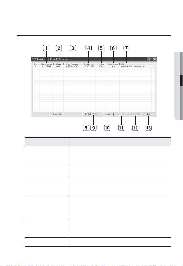
BUTTONS USED IN IP INSTALLER
Item Description
Device Name
Model name of the connected camera.
Click the column to sort the list by model name.
However, search will be stopped if clicked during the search.
b
Mode
Displays either <Static> or <Dynamic> for the current network connection
status.
c
MAC(Ethernet)
Address
Ethernet address for the connected camera.
Click the column to sort the list by Ethernet address.
However, search will be stopped if clicked during the search.
IP Address
IP address.
Click the column to sort the list by IP address.
However, search will be stopped if clicked during the search.
The factory default is “192.168.1.100”.
Protocol
Network setting for the camera.
The factory default is “IPv4”.
Cameras with the IPv6 setting will be displayed “IPv6”.
UPnP Status This function is not currently implemented.

30_ network connection and setup
network connection and setup
Item Description
URL
DDNS URL address enabling access from the external Internet.
However, this will be replaced with the <IP Address> of the camera if
DDNS registration has failed.
IPv4 Scans for cameras with the IPv4 setting.
IPv6 Scans for cameras with the IPv6 setting.
Search
Scans for cameras that are currently connected to the network.
However, this button will be grayed out if neither IPv4 nor IPv6 is checked.
Auto Set The IP Installer automatically configures the network settings.
Manual Set You should configure the network settings manually.
m
Exit Exits the IP Installer program.
M
For the IP installer, use only the installer version provided in the installation CD or use the
latest one if available. You can download the latest version from the Samsung web site (www.
samsungipolis.com).
STATIC IP SETUP
Manual Network Setup
Run <IP Installer_vX.XX.exe> to display the camera search list.
At the initial startup, both [Auto Set] and [Manual Set] will be grayed out.
M
For cameras found with the IPv6 setting, these buttons will be grayed out as the cameras do not
support this function.
1. Select a camera in the search list.
Find the MAC (Ethernet) address
labeled on the rear of the camera.
Both the [Auto Set] and [Manual Set]
buttons will be activated.
2. Click [Manual Set].
The Manual Setting dialog appears.
The default values of <IP Address>,
<Subnet Mask>, <Gateway>, <HTTP Port> and <VNP Port> of the camera will
be displayed.
 Loading...