


NETWORK CAMERA
User Manual
SND-5011/SND-5061/ SND-7011/SND-7061
Network Camera
User Manual
Copyright
©2012 Samsung Techwin Co., Ltd. All rights reserved.
Trademark
 is the registered logo of Samsung Techwin Co., Ltd. The name of this product is the registered trademark of Samsung Techwin Co., Ltd.
Other trademarks mentioned in this manual are the registered trademark of their respective company.
Restriction
Samsung Techwin Co., Ltd shall reserve the copyright of this document. Under no circumstances, this document shall be reproduced, distributed or changed, partially or wholly, without formal authorization of Samsung Techwin.
Disclaimer
Samsung Techwin makes the best to verify the integrity and correctness of the contents in this document, but no formal guarantee shall be provided. Use of this document and the subsequent results shall be entirely on the user’s own responsibility. Samsung Techwin reserves the right to change the contents of this document without prior notice.
Design and specifications are subject to change without prior notice.
The default password can be exposed to a hacking thread so it is recommended to change the password after installing the product.
Note that the security and other related issues caused by the unchanged password shall be responsible for the user.

overview
Important Safety Instructions
1. |
Read these instructions. |
|
|
2. |
Keep these instructions. |
|
|
3. |
Heed all warnings. |
● |
|
4. |
Follow all instructions. |
overview |
|
|
|
||
5. |
Do not use this apparatus near water. |
|
|
6. |
Clean only with dry cloth. |
|
|
7. |
Do not block any ventilation openings, Install in accordance with the manufacturer’s |
|
|
8. |
instructions. |
|
|
Do not install near any heat sources such as radiators, heat registers, stoves, or other |
|
|
|
9. |
apparatus (including amplifiers) that produce heat. |
|
|
Do not defeat the safety purpose of the polarized or grounding-type plug. A polarized |
|
|
|
|
plug has two blades with one wider than the other. A grounding type plug has two |
|
|
|
blades and a third grounding prong. The wide blade or the third prong are provided for |
|
|
|
your safety. If the provided plug does not fit into your outlet, consult an electrician for |
|
|
10. |
replacement of the obsolete outlet. |
|
|
Protect the power cord from being walked on or pinched particularly at plugs, |
|
|
|
11. |
convenience receptacles, and the point where they exit from the apparatus. |
|
|
Only use attachments/ accessories specified by the manufacturer. |
|
|
|
12. |
Use only with the cart, stand, tripod, bracket, or table specified by |
|
|
|
the manufacturer, or sold with the apparatus. When a cart is used, |
|
|
|
use caution when moving the cart/apparatus combination to avoid |
|
|
13. |
injury from tip-over. |
|
|
Unplug this apparatus during lighting storms or when unused for |
|
|
|
14. |
long periods of time. |
|
|
Refer all servicing to qualified service personnel. Servicing is required when the |
|
|
|
|
apparatus has been damaged in any way, such as power-supply cord or plug is |
|
|
|
damaged, liquid has been spilled or objects have fallen into the apparatus, the apparatus |
|
|
|
has been exposed to rain or moisture, does not operate normally, or has been dropped. |
|
|
English _3
overview
WARNING
TO REDUCE THE RISK OF FIRE OR ELECTRIC SHOCK, DO NOT EXPOSE THIS PRODUCT TO RAIN OR MOISTURE. DO NOT INSERT ANY METALLIC OBJECT THROUGH THE VENTILATION GRILLS OR OTHER OPENNINGS ON THE EQUIPMENT.
Apparatus shall not be exposed to dripping or splashing and that no objects filled with liquids, such as vases, shall be placed on the apparatus.
CAUTION
CAUTION
RISK OF ELECTRIC SHOCK.
DO NOT OPEN
CAUTION : TO REDUCE THE RISK OF ELECTRIC SHOCK.
DO NOT REMOVE COVER (OR BACK).
NO USER SERVICEABLE PARTS INSIDE.
REFER SERVICING TO QUALIFIED SERVICE PERSONNEL.
EXPLANATION OF GRAPHICAL SYMBOLS
The lightning flash with arrowhead symbol, within an equilateral triangle, is intended to alert the user to the presence of “dangerous voltage” within the product’s enclosure that may be of sufficient magnitude to constitute a risk of electric shock to persons.
The exclamation point within an equilateral triangle is intended to alert the user to the presence of important operating
and maintenance (servicing) instructions in the literature accompanying the product.
4_ overview
Class  construction
An apparatus with CLASS construction shall be connected to a MAINS socket outlet with a protective earthing connection.
Battery
Batteries(battery pack or batteries installed) shall not be exposed to excessive heat such as sunshine, fire or the like.
Disconnection Device
Disconnect the main plug from the apparatus, if it’s defected. And please call a repair man in your location.
When used outside of the U.S., it may be used HAR code with fittings of an approved agency is employed.
CAUTION
These servicing instructions are for use by qualified service personnel only. To reduce the risk of electric shock do not perform any servicing other than that contained in the operating instructions unless you are qualified to do so.
The BNC Out terminal of the product is provided for easier installation, and is not recommended for monitoring purposes.
If you keep the BNC cable connected, a risk of lightening may cause damage or malfunction to the product.
Please use the input power with just one camera and other devices must not be connected.
overview ●
English _5

overview
Please read the following recommend safety precautions carefully.
yyDo not place this apparatus on an uneven surface.
yyDo not install on a surface where it is exposed to direct sunlight, near heating equipment or heavy cold area.
yyDo not place this apparatus near conductive material. yyDo not attempt to service this apparatus yourself. yyDo not place a glass of water on the product.
yyDo not install near any magnetic sources. yyDo not block any ventilation openings. yyDo not place heavy items on the product.
User’s Manual is a guidance book for how to use the products. The meaning of the symbols are shown below.
yyReference : In case of providing information for helping of product’s usages
yyNotice : If there’s any possibility to occur any damages for the goods and human caused by not following the instruction
Please read this manual for the safety before using of goods and keep it in the safe place.
6_ overview

CONTENTS
overview |
9 |
Product Features |
3 |
3 |
Important Safety Instructions |
9 |
Recomended PC Specifications |
|
10 |
What’s Included |
|
11 |
At a Glance |
|
|
14 |
(SND-5011/SND-7011) |
|
At a Glance |
(SND-5061/SND-7061)
overview ●
installation & connection
17
network connection and setup
28
17 Installation (SND-5011/SND-7011)
19 Installation (SND-5061/SND-7061)
25 Connecting with other Device
28 Connecting the Camera Directly to Local Area Networking
29 Connecting the Camera Directly to a DHCP Based DSL/Cable Modem
30 Connecting the Camera Directly to a PPPoE Modem
31 Connecting the Camera to a Broadband Router with the PPPoE/Cable Modem
32 Buttons used in IP Installer
33 Static IP Setup
37 Dynamic IP Setup
38 Port Range Forward (Port Mapping) Setup
40 Connecting to the Camera from a Shared Local PC
40Connecting to the Camera from a Remote PC via the Internet
English _7

overview
web viewer |
42 |
Login |
41 |
41 |
Connecting to the Camera |
43 |
Installing STW WebViewer Plugin |
|
44 |
Using the Live Screen |
|
setup screen |
46 |
Video Setup |
46 |
46 |
Setup |
57 |
Network Setup |
|
66 |
Event Setup |
|
73 |
System Setup |
|
appendix |
85 |
Product Overview |
79 |
79 |
Specification |
87 |
Troubleshooting |
|
88 |
Open Source Announcement |
|
89 |
License |
|
|
92 |
GPL/LGPL Software License |
8_ overview

Product Features
•• Multi-Streaming
This network camera can display videos in different resolutions and qualities simultaneously using different CODECs.
•• Web Browser-based Monitoring
Using the Internet web browser to display the image in a local network environment.
•• Alarm
If an event occurs, the event-related video will be transferred to the email or FTP server specified by the user.
•• Video Motion Detection
Detects a motion from the video before triggering an event.
•• Screen change detection feature
If the monitoring is interrupted in any way, the camera will trigger the event alarm.
•• ONVIF Compliance
This product supports ONVIF.
For more information, refer to www.onvif.org.
Recomended PC Specifications
•• CPU : Intel(R) Core(TM)2 2.4 GHz or higher
•• Operating System : Windows XP, VISTA, 7, Mac OS
•• Resolution : 1280X1024 pixels or higher (32 bit color)
•• RAM : 2GB or higher
•• Web Browser : Internet Explorer 7 or later, Firefox 9 or later, Chrome 15 or later, Safari 5.1 or later
`` Neither a beta test version unlike the version released in the company website nor the developer version will be supported.
`` It is recommended to connect to IPv6 in Windows 7.
•• Video Memory : 256MB or higher
JJ`` If the driver of the video graphic adapter is not installed properly or is not the latest version, the video may not be played properly.
`` For a multi-monitoring system involving at least 2 monitors, the playback performance can be deteriorated depending on the system.
overview ●
English _9

overview
What’s Included
Please check if your camera and accessories are all included in the product package.
Appearance |
Item Name |
Quantity |
Description |
Model Name |
|
Camera |
1 |
|
SND-5011/SND-7011 |
|
|
or |
||
|
|
|
|
SND-5061/SND-7061 |
|
Instruction book, |
2 |
|
|
|
Installer S/W CD, |
|
|
|
|
CMS S/W DVD |
|
|
|
|
Quick Guide (Optional) |
1 |
|
|
|
Cable for the testing |
|
Used to test the camera |
|
|
1 |
connection to a portable |
|
|
|
monitor |
|
||
|
|
display device |
|
|
|
|
|
|
|
|
Iron Screw |
3 |
Used for fixing to an iron |
|
|
plate |
|
||
|
|
|
|
10_ overview
At a Glance (SND-5011/SND-7011)
Appearance
a
b
c d e
Item |
|
Description |
|
a Dome Cover |
Dome cover for the lens and unit protection. |
||
b Main unit |
Main unit includes the lens, switch board, PCB boards and screws. |
||
c Power Port |
Used to plug the power cable. |
||
d Alarm Input Port |
BROWN = Alarm IN |
Used to connect the alarm input sensor. |
|
BLACK = GND |
Used for earth-grounding. |
||
|
|||
e Network Port |
Used to connect a PoE or LAN cable. |
||
|
|
|
|
overview ●
English _11

overview
Components
c


 a
a 

 b
b 
|
d |
|
e |
|
f |
Item |
Description |
a Monitor to install |
Using the test monitor cable, you can connect to a mobile display for camera |
test. |
Resets the camera settings to the default.
Press and hold for about 5 seconds to reboot the system.
b Reset Button J If you reset the camera, the network settings will be adjusted so that DHCP can be enabled. If there is no DHCP server in the network, you must run the IP Installer program to change the basic network settings such as IP address, Subnet mask, Gateway, etc., before you can connect to the network.
12_ overview

Item |
Description |
c Inner Cover |
Cover used to protect the main unit. |
|
|
d Bracket |
Used to install the camera on the wall or ceiling with the screws. |
|
|
e Wiring Cover |
If installation requires drilling, run the cable through here. |
|
|
f Lock Release |
To separate the bracket from the main unit for the installation or to separate |
the camera from an installed camera, push this release and turn the main |
|
|
unit in the marked direction of <UNLOCK>. |
overview ●
English _13
overview
At a Glance (SND-5061/SND-7061)
Appearance
a
b
c d e
Item |
|
Description |
|
a Dome Cover |
Dome cover for the lens and unit protection. |
||
b Main unit |
Main unit includes the lens, switch board, PCB boards and screws. |
||
c Power Port |
Used to plug the power cable. |
||
d Alarm Input Port |
BROWN = Alarm IN |
Used to connect the alarm input sensor. |
|
BLACK = GND |
Used for earth-grounding. |
||
|
|||
e Network Port |
Used to connect a PoE or LAN cable. |
||
|
|
|
|
14_ overview

Components
a
e
b

 c
c  d
d
f
g
h
overview ●
Item |
Description |
a Focus Lever |
Turn it to the left or right to adjust the focus; turn it clockwise to fix the focus. |
b Zoom Lever |
Used to adjust or fix the zoom factor of the lens. |
c Monitor to install |
Using the test monitor cable, you can connect to a mobile display for camera |
test. |
English _15

overview
Item |
Description |
|
Resets the camera settings to the default. |
|
Press and hold for about 5 seconds to reboot the system. |
d Reset Button |
J If you reset the camera, the network settings will be adjusted so that |
DHCP can be enabled. If there is no DHCP server in the network, you |
|
|
must run the IP Installer program to change the basic network settings |
|
such as IP address, Subnet mask, Gateway, etc., before you can |
|
connect to the network. |
e Inner Cover |
Cover used to protect the main unit. |
|
|
f Bracket |
Used to install the camera on the wall or ceiling with the screws. |
|
|
g Wiring Cover |
If installation requires drilling, run the cable through here. |
|
|
h Lock Release |
To separate the bracket from the main unit for the installation or to separate |
the camera from an installed camera, push this release and turn the main |
|
|
unit in the marked direction of <UNLOCK>. |
16_ overview
installation & connection
Installation (SND-5011/SND-7011)
Precautions before installation
Ensure you read out the following instructions before installing the camera:
•• Select an installation site (ceiling or wall) that can endure at least 5 times of the camera weight.
•• Stuck-in or peeled-off cables can cause damage to the product or a fire.
•• For safety purposes, keep anyone else away from the installation site. And put aside personal belongings from the site, just in case.
Disassembling
1.Use one hand to hold the camera’s bottom part and turn the cover counterclockwise with another hand to separate it.
2. Lift up the inner cover to separate it.
connectionin&sta●ationll
English _17

installation & connection
3. While pushing the ratchet toward <UNLOCK> direction outwards, turn the bracket to <UNLOCK> direction using bottom groove to separate it.
Installation
1.Use the provided screws (x3) to fix the bracket to a desired position (ceiling or wall).
`Ensure that the <FRONT> label on the bracket faces the
direction for camera monitoring.`
2. Arrange the cables through the bracket to the ceiling or wall.
`` If you intend to drill a hole in the installation site for the wiring purpose, remove the wiring cover by force to reveal
a hole. Arrange the cables through the hole. If you intend
to arrange the cables without drilling a hole, use the empty area opposite to the <FRONT> label side for the wiring
purpose.
3. Mount the main unit onto the bracket.
Align the marking hole of the main unit with the <FRONT> label of the bracket, and turn the unit in the <LOCK> direction.
4. Adjust the lens in a desired direction.
For adjusting the lens direction, refer to “Adjusting the monitoring direction for the camera”. (page 21)
5. Fix the cover to the main unit.
`` Fit the protruding part inside the cover into the corresponding hole of the main unit, and turn the cover to fix it.
18_ installation & connection

Installation (SND-5061/SND-7061)
Precautions before installation
Ensure you read out the following instructions before installing the camera:
•• Select an installation site (ceiling or wall) that can endure at least 5 times of the camera weight.
•• Stuck-in or peeled-off cables can cause damage to the product or a fire.
•• For safety purposes, keep anyone else away from the installation site. And put aside personal belongings from the site, just in case.
Disassembling
1.Use one hand to hold the camera’s bottom part and turn the cover counterclockwise with another hand to separate it.
2. Lift up the inner cover to separate it.
connectionin&sta●ationll
English _19

installation & connection
3. While pushing the ratchet toward <UNLOCK> direction outwards, turn the bracket to <UNLOCK> direction using bottom groove to separate it.
Installation
1.Use the provided screws (x3) to fix the bracket to a desired position (ceiling or wall).
`Ensure that the <FRONT> label on the bracket faces the
direction for camera monitoring.`
2. Arrange the cables through the bracket to the |
|
|
ceiling or wall. |
|
|
` |
If you intend to drill a hole in the installation site for the |
|
` |
wiring purpose, remove the wiring cover by force to reveal |
|
|
a hole. Arrange the cables through the hole. If you intend |
|
|
to arrange the cables without drilling a hole, use the empty |
|
|
area opposite to the <FRONT> label side for the wiring |
Wiring Cover |
|
purpose. |
|
3.Mount the main unit onto the bracket.
Align the marking hole of the main unit with the <FRONT> label of the bracket, and turn the unit in the <LOCK> direction.
4.Adjust the lens in a desired direction.
For adjusting the lens direction, refer to “Adjusting the monitoring direction for the camera”. (page 23)
5.Fix the cover to the main unit.
`` Fit the protruding part inside the cover into the corresponding hole of the main unit, and turn the cover to fix it.
20_ installation & connection
Adjusting the monitoring direction for the camera (SND-5011/SND-7011)
Panning
Tilting
Lens rotation
JJ`` The part marked shaded above acts as heat sinker pad to lose the product’s heat. While powered, it gets hot and requires safety attention.
Adjusting the monitoring direction
You can adjust the camera direction only when the camera is fixed on the ceiling. Then, turning the camera to the left or right is referred to as “Panning”, while tilting the
angle is “Tilting”. For panning, the panning limit is 176° for the clockwise, and 176° for the counterclockwise, a total of 352° enabled; further rotation is stopped by the stopper.
-- Adjust the panning angle so that the camera settles in the right horizontal position. You can adjust the panning up to 176° in each one direction, and 176° in the other direction, a total of 352°.
-- Adjust the tilting angle so that the camera settles in the right vertical position. You can adjust the tilting between 0° and 90°.
-- The total rotation range is 352°. You can make adjustment in one direction up to 125°, and 227° in the other direction.
connectionin&sta●ationll
English _21

installation & connection
Methods of adjustment
•• The case of wall installation
After mounting the camera on the wall, adjust the panning angle so that the camera faces a desired direction when tilting.
Adjust the Rotate position to fit the video to the screen borders.
Then, adjust the tilting angle so that the camera faces the monitoring direction.
•• The case of ceiling installation
After mounting the camera on the ceiling, adjust the panning angle according to the monitoring direction. You should adjust the panning angle lest that the video be displayed upside down on the monitor.
Adjust the Rotate position to fit the video to the screen borders.
Then, adjust the tilting angle so that the camera faces the monitoring direction.
JJ`` For smoother Rotate adjustment, set the Tilt position between 60° ~ 80°.
22_ installation & connection

Adjusting the monitoring direction for the camera (SND-5061/SND-7061)
Panning
Tilting
Lens rotation
connectionin&sta●ationll
JJ`` The part marked shaded above acts as heat sinker pad to lose the product’s heat. While powered, it gets hot and requires safety attention.
Adjusting the monitoring direction
You can adjust the camera direction only when the camera is fixed on the ceiling.
Then, turning the camera to the left or right is referred to as “Panning”, while tilting the angle is “Tilting”. For panning, the panning limit is 177.5° for the clockwise, and 177.5° for the counterclockwise, a total of 355° enabled; further rotation is stopped by the stopper.
-- Adjust the panning angle so that the camera settles in the right horizontal position. You can adjust the panning up to 177.5° in each one direction, and 177.5° in the other direction, a total of 355°.
-- Adjust the tilting angle so that the camera settles in the right vertical position. You can adjust the tilting between 17° and 90°.
-- The total rotation range is 355°. You can make adjustment in one direction up to 125°, and 230° in the other direction.
English _23

installation & connection
Methods of adjustment
•• The case of wall installation
After mounting the camera on the wall, adjust the panning angle so that the camera faces a desired direction when tilting.
Adjust the Rotate position to fit the video to the screen borders.
Then, adjust the tilting angle so that the camera faces the monitoring direction.
•• The case of ceiling installation
After mounting the camera on the ceiling, adjust the panning angle according to the monitoring direction. You should adjust the panning angle lest that the video be displayed upside down on the monitor.
Adjust the Rotate position to fit the video to the screen borders.
Then, adjust the tilting angle so that the camera faces the monitoring direction.
JJ`` For smoother Rotate adjustment, set the Tilt position between 60° ~ 80°.
24_ installation & connection
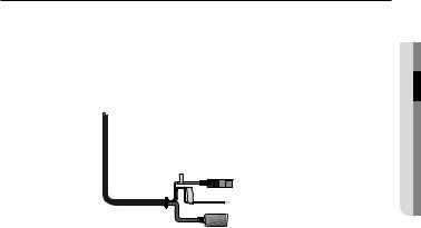
Connecting with other Device
connectionin&sta●ationll
Monitor to install
Power
Ethernet
JJ`` The BNC Out terminal of the product is provided for easier installation, and is not recommended for monitoring purposes.
If you keep the BNC cable connected, a risk of lightening may cause damage or malfunction to the product.
Ethernet Connection
Connect the Ethernet cable to the local network or to the Internet.
Power Supply
Use the screwdriver to connect each line (+, –) of the power cable to the corresponding power port of the camera.
JJ`` IfPoE.both PoE and DC12V are applied simultaneously, the product will be supplied with power from
-- You can also use a router featuring PoE (Power over Ethernet) to supply power to the camera. -- Use PoE (Power over Ethernet) that is compliant with the IEEE802.3af protocols.
-- It is advisable to use only one power source from PoE and DC12V.
English _25
installation & connection
`` Be careful not to reverse the polarity when you connect the power cable.
-- Please connect the power adapter when the installation is completed.
-- As shown in the table below, you may encounter a voltage-sag depending on the wire length. If you use an excessively long wire for camera connection, the camera may not work properly.
Electrical Resistance of Copper Wire at [20°C (68°F)] |
|
|
||||||||||||
|
|
Copper Wire Gauge (AWG) |
#24(0.22mm2) |
#22(0.33mm2) |
#20(0.52mm2) |
#18(0.83mm2) |
||||||||
|
|
Resistance (Ω/m) |
0.078 |
|
0.050 |
0.030 |
0.018 |
|||||||
|
|
Drop Voltage (V/m) |
0.028 |
|
0.018 |
0.011 |
0.006 |
|||||||
|
|
Recommended Distance (m) |
Less than 20 |
|
Less than 30 |
Less than 30 |
Less than 30 |
|||||||
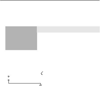
Alarm input Wiring Diagram |
|
|
|
|
||||||||||
|
|
|
|
|
|
|
|
|
|
|
|
|
||
|
|
|
|
|
|
|
|
|
(5mA sink) |
|
|
|
|
|
|
1 |
|
|
|
|
|
|
|
|
|||||
|
|
ALARM IN |
|
|
|
|
|
|
|
|
|
|
|
|
|
|
|
|
|
|
|
|
|
|
|
|
|
|
|
|
|
|
|
|
|
|
|
|
|
|
|
|
||
|
|
|
|
|
|
|
|
|
|
|
|
|
|
|
|
|
|
2 |
|
|
|
|
|
|
|
|
|
|
|
|
|
|
|
|
|
|
|
|
|
|
||||
|
|
GND |
|
|
|
|
|
|
|
|
|
|
|
|
|
|
|
|
|
|
|
|
|
|
|
||||
|
|
|
|
|
|
|
|
|
|
|
|
|
|
|
|
|
|
|
|
|
|
|
|
|
|
|
|
|
|
26_ installation & connection

To connect to the alarm input port
Connect the alarm input cable to the corresponding port.
connectionin&sta●ationll
B
ROWN ALARM BLACK GND
IN
|
|
|
|
|
|
|
|
|
SENSOR |
|
|
|
|
|
|
|
|
|
|
||
|
|
|
|
|
|
|
|
|
||
|
|
|
|
|
|
|
|
|
||
|
|
|
|
|
|
|
|
|
|
|
Port |
Description |
|
|
|
|
|
Port |
Description |
||
ALARM IN |
Alarm Input Sensor Port |
|
|
|
|
|
GND |
GND port for the sensor |
|
|
To connect the external sensor
Connect one strand of each signal line (2-strand) of the sensors to the [ALARM IN] port, and connect the other strand to the [GND] port.
English _27

network connection and setup
You can set up the network settings according to your network configurations.
Connecting the Camera Directly to Local Area Networking
Connecting to the camera from a local PC in the LAN
1.Launch an Internet browser on the local PC.
2.Enter the IP address of the camera in the address bar of the browser.
Camera |
Camera |
INTERNET 
Firewall |
External Remote PC |
Local PC |
DDNS Server |
(Data Center, KOREA) |
<Local Network>
MM`` A remote PC in an external Internet out of the LAN network may not be able to connect to the camera installed in the intranet if the port-forwarding is not properly set or a firewall is set. In this case, to resolve the problem, contact your network administrator.
`` By factory default, the IP address will be assigned from the DHCP server automatically. If there is no DHCP server available, the IP address will be set to 192.168.1.100.
To change the IP address, use the IP Installer.
For further details on IP Installer use, refer to “Static IP Setup”. (Page 33)
28_ network connection and setup

Connecting the Camera Directly to a DHCP Based DSL/Cable Modem
|
INTERNET |
|
DSL/Cable Modem |
Camera |
External Remote PC |
DDNS Server
(Data Center, KOREA)
1.Use the cross LAN cable to connect the network cable directly to your PC.
2.Run the IP Installer and change the IP address of the camera so that you can use the web browser on your desktop to connect to the Internet.
3.Use the Internet browser to connect to the camera.
4.Move to [Setup] page.
5.Move to [Network] – [DDNS] and configure the DDNS settings.
6.Move to [Network] – [Interface], and set the network type to [DHCP].
7.Connect the camera, which was removed from your PC, directly to the modem.
8.Restart the camera.
MM`` For registering the DDNS settings, refer to “Registering with DDNS”. (page 60)
`` For configuring the DDNS settings, refer to “DDNS”. (page 59) `` For setting the network type, refer to “Interface”. (page 57)
etupd s
networan connection● k
English _29

network connection and setup
Connecting the Camera Directly to a PPPoE Modem
|
INTERNET |
|
PPPoE Modem |
Camera |
External Remote PC |
DDNS Server
(Data Center, KOREA)
1.Use the cross LAN cable to connect the network cable directly to your PC.
2.Run the IP Installer and change the IP address of the camera so that you can use the web browser on your desktop to connect to the Internet.
3.Use the Internet browser to connect to the camera.
4.Move to [Setup] page.
5.Move to [Network] – [DDNS] and configure the DDNS settings.
6.Move to [Network] – [Interface], and set the network type to [PPPoE].
7.Connect the camera, which was removed from your PC, directly to the modem.
8.Restart the camera.
MM`` For registering the DDNS settings, refer to “Registering with DDNS”. (page 60)
`` For configuring the DDNS settings, refer to “DDNS”. (page 59) `` For setting the network type, refer to “Interface”. (page 57)
30_ network connection and setup
 Loading...