


Advanced Information
Fixed Frequency PWM
Micropower DC-to-DC
Converter
The MC33466 series are micropower switching voltage regulators, specifically designed for handheld and laptop applications, to provide regulated output voltages using a minimum of external parts. A wide choice of output voltages are available. These devices feature a very low quiescent bias current of 15 μA typical.
The MC33466H±XXJT1 series features a highly accurate voltage reference, an oscillator, a pulse width modulation (PWM) controller, a driver transistor (Lx), an error amplifier and feedback resistive divider.
The MC33466H±XXLT1 is identical to the MC33466H±XXJT1, except that a drive pin (EXT) for an external transistor is provided.
Due to the low bias current specifications, these devices are ideally suited for battery powered computer, consumer, and industrial equipment where an extension of useful battery life is desirable.
MC33466 Series Features:
•Low Quiescent Bias Current of 15 μA
•High Output Voltage Accuracy of ±2.5%
•Low Startup Voltage of 0.9 V at 1.0 mA
•Soft±Start = 500 μs
•Surface Mount Package
ORDERING INFORMATION
|
Output |
|
Operating |
Package |
|
Device |
Voltage |
Type |
Temperature Range |
(Tape/Reel) |
|
|
|
|
|
|
|
MC33466H±30JT1 |
3.0 |
Int. |
|
SOT±89 |
|
MC33466H±33JT1 |
3.3 |
Switch |
|
(Tape) |
|
MC33466H±50JT1 |
5.0 |
|
TA = ±30° to +80°C |
|
|
|
|
|
|
||
MC33466H±30LT1 |
3.0 |
Ext. |
SOT±89 |
||
|
|||||
MC33466H±33LT1 |
3.3 |
Switch |
|
(Tape) |
|
MC33466H±50LT1 |
5.0 |
Drive |
|
|
|
|
|
|
|
|
Other voltages from 2.5 V to 7.5 V, in 0.1 V increments are available. Consult factory for information.
Order this document by MC33466/D
MC33466
FIXED FREQUENCY PWM MICROPOWER DC±to±DC CONVERTER
SEMICONDUCTOR
TECHNICAL DATA
TAB
1
H SUFFIX
PLASTIC PACKAGE
CASE 1213
(SOT±89)
PIN CONNECTIONS
MC33466H±XXJT1
|
|
|
|
|
Ground |
1 |
|
|
|
|
|
|
|
|
Output |
2 |
|
|
Tab |
Lx |
|
|
|
(Tab is connected |
3 |
|
|||
|
|
to Pin 2) |
||
|
|
|
|
|
|
|
(Top View) |
||
MC33466H±XXLT1 |
||||
|
|
|
|
|
|
|
|
|
|
Ground |
1 |
|
|
|
|
|
|
|
|
Output |
2 |
|
|
Tab |
EXT |
|
|
|
(Tab is connected |
3 |
|
|
||
|
|
to Pin 2) |
||
|
|
|
|
|
|
|
(Top View) |
||
This document contains information on a new product. Specifications and information herein |
Motorola, Inc. 1997 |
Rev 1 |
are subject to change without notice. |
|
|

MC33466
Representative Block Diagrams
MC33466H±XXJT1
D
L |
VO |
3 |
VLx Limiter |
|
2 |
|
Vin |
|
Output |
|
|
Lx |
|
|
CO |
|
Cin |
Drive |
|
(Voltage |
|
|
|
Feedback) |
|
|
|
|
|
|
|
|
PWM |
|
|
|
|
Controller |
|
|
|
|
|
Phase |
|
|
|
50 kHz |
Comp |
|
|
|
Oscillator |
Vref |
|
|
|
|
|
|
|
|
|
Soft±Start |
|
|
|
|
1 |
Gnd |
|
L |
|
MC33466H±XXLT1 |
|
|
Vin |
|
|
D |
|
|
|
|
|
|
Cin |
|
|
2 |
VO |
Rb |
3 |
|
Output |
CO |
Drive |
(Voltage |
|||
Q |
EXT |
Feedback) |
|
|
|
|
|
|
|
Cb |
|
PWM |
|
|
|
|
Controller |
|
|
|
|
|
Phase |
|
|
|
50 kHz |
Comp |
|
|
|
Oscillator |
Vref |
|
|
|
|
|
|
|
|
|
Soft±Start |
|
|
|
|
1 Gnd |
|
XX Denotes Output Voltage
This device contains 100 active transistors.
MAXIMUM RATINGS (TC = 25°C, unless otherwise noted.)
Rating |
Symbol |
Value |
Unit |
|
|
|
|
Power Supply Voltage (Transient) |
VO |
12 |
V |
Power Supply Voltage (Operating) |
VO |
8.0 |
V |
External Pin Voltage |
VEXT |
±0.3 to VO |
V |
Lx Pin Voltage |
VLx |
12 |
V |
EXT Pin Source/Sink Current |
IEXT |
50/50 |
mA |
Lx Pin Sink Current |
ILx |
250 |
mA |
Power Dissipation and Thermal Characteristics |
|
|
|
|
|
|
|
H Suffix, Plastic Package Case 1213 (SOT±89) |
|
|
|
Maximum Power Dissipation @ TA = 25°C |
PD |
500 |
mW |
Thermal Resistance, Junction±to±Air |
RθJA |
200 |
°C/W |
Operating Junction Temperature |
TJ |
125 |
°C |
Operating Ambient Temperature |
TA |
±30 to +80 |
°C |
Storage Temperature Range |
Tstg |
±40 to +125 |
°C |
NOTE: ESD data available upon request.
2 |
MOTOROLA ANALOG IC DEVICE DATA |

MC33466
ELECTRICAL CHARACTERISTICS (VCC = 2.0 V, IO = 10 mA and TA = 25°C, unless otherwise noted.)
Characteristic |
Symbol |
Min |
Typ |
Max |
Unit |
|
|
|
|
|
|
|
|
OSCILLATOR |
|
|
|
|
|
|
|
|
|
|
|
|
|
Frequency |
fosc |
40 |
50 |
60 |
kHz |
|
Oscillator Minimum Startup Voltage (IO = 0 mA) |
Vstart |
± |
0.8 |
0.9 |
V |
|
Oscillator Minimum Supply Voltage (IO = 0 mA) |
VCC |
0.7 |
± |
± |
V |
|
LX OUTPUT (JT1 SUFFIX) |
|
|
|
|
|
|
|
|
|
|
|
|
|
ON State Sink Current (VLx = 0.4 V) |
ILx |
|
|
|
mA |
|
30KT1 Suffix |
|
60 |
± |
± |
|
|
33KT1 Suffix |
|
63 |
± |
± |
|
|
50KT1 Suffix |
|
80 |
± |
± |
|
|
|
|
|
|
|
|
|
VLx Voltage Limit (Note 1) |
VLxLim |
0.65 |
0.8 |
1.0 |
V |
|
OFF State Leakage Current (VLx = 6.0 V) |
ILKG |
± |
± |
0.5 |
μA |
|
EXT OUTPUT (LT1 SUFFIX) |
|
|
|
|
|
|
|
|
|
|
|
|
|
ON State Source Current (VEXT = VO ± 0.4 V) |
Isource |
|
|
|
mA |
|
30LT1 Suffix |
|
1.5 |
± |
± |
|
|
33LT1 Suffix |
|
1.575 |
± |
± |
|
|
50LT1 Suffix |
|
2.0 |
± |
± |
|
|
|
|
|
|
|
|
|
OFF State Sink Current (VEXT = 0.4 V) |
Isink |
|
|
|
mA |
|
30LT1 Suffix |
|
1.5 |
± |
± |
|
|
33LT1 Suffix |
|
1.575 |
± |
± |
|
|
50LT1 Suffix |
|
2.0 |
± |
± |
|
|
|
|
|
|
|
|
|
TOTAL DEVICE |
|
|
|
|
|
|
|
|
|
|
|
|
|
Maximum Duty Ratio Each Cycle |
D |
70 |
80 |
90 |
% |
|
|
|
|
|
|
|
|
Output Voltage |
VO |
|
|
|
V |
|
30KT1 or 30LT1 Suffix |
|
2.925 |
3.0 |
3.075 |
|
|
33KT1 or 33LT1 Suffix |
|
3.218 |
3.3 |
3.383 |
|
|
50KT1 or 50LT1 Suffix |
|
4.875 |
5.0 |
5.125 |
|
|
|
|
|
|
|
|
|
Soft±Start Time (Note 2) |
Tss |
0.5 |
2.0 |
± |
ms |
|
Quiescent Bias Current (Vin = 2.0 V, IO = 0 mA) |
IQ |
|
|
|
μA |
|
30JT1 Suffix |
|
± |
15 |
25 |
|
|
33JT1 Suffix |
|
± |
17 |
27 |
|
|
50JT1 Suffix |
|
± |
30 |
45 |
|
|
Quiescent Bias Current (Vin = VO + 0.5 V, IO = 0 mA) |
|
|
|
|
|
|
30JT1 Suffix |
|
± |
1.2 |
5.0 |
|
|
33JT1 Suffix |
|
± |
1.2 |
5.0 |
|
|
50JT1 Suffix |
|
± |
2.0 |
5.0 |
|
|
|
|
|
|
|
|
|
Quiescent Bias Current (Vin = 2.0 V, IO = 0 mA) |
IQ |
|
|
|
μA |
|
30LT1 Suffix |
|
± |
30 |
50 |
|
|
33LT1 Suffix |
|
± |
34.5 |
56 |
|
|
50LT1 Suffix |
|
± |
60 |
90 |
|
|
Quiescent Bias Current (Vin = VO + 0.5 V, IO = 0 mA) |
|
|
|
|
|
|
30LT1 Suffix |
|
± |
1.2 |
5.0 |
|
|
33LT1 Suffix |
|
± |
1.2 |
5.0 |
|
|
50LT1 Suffix |
|
± |
2.0 |
5.0 |
|
|
|
|
|
|
|
|
|
NOTES: 1. When the Lx switch is turned on, ILx current carried through the RDS(on) of the Lx switch results in VLx. When VLx reaches VLxLim, the Lx switch is turned off by the Lx switch protection circuit.
2.The soft±start circuit turn±on sequence is as follows:
a)Vin is applied.
b)The internal IC Vref is held at zero for 200 μs. During this time, the error amplifier output voltage ramps up to the positive voltage rail.
c)The internal reference steps up to 0.7 V after 200 μs delay has timed out.
d)The error amplifier output voltage integrates down to its steady state value. As the error amplifier output integrates down, the output Lx pin of EXT pin pulse width gradually widens to its steady operating value.
MOTOROLA ANALOG IC DEVICE DATA |
3 |
|
MC33466
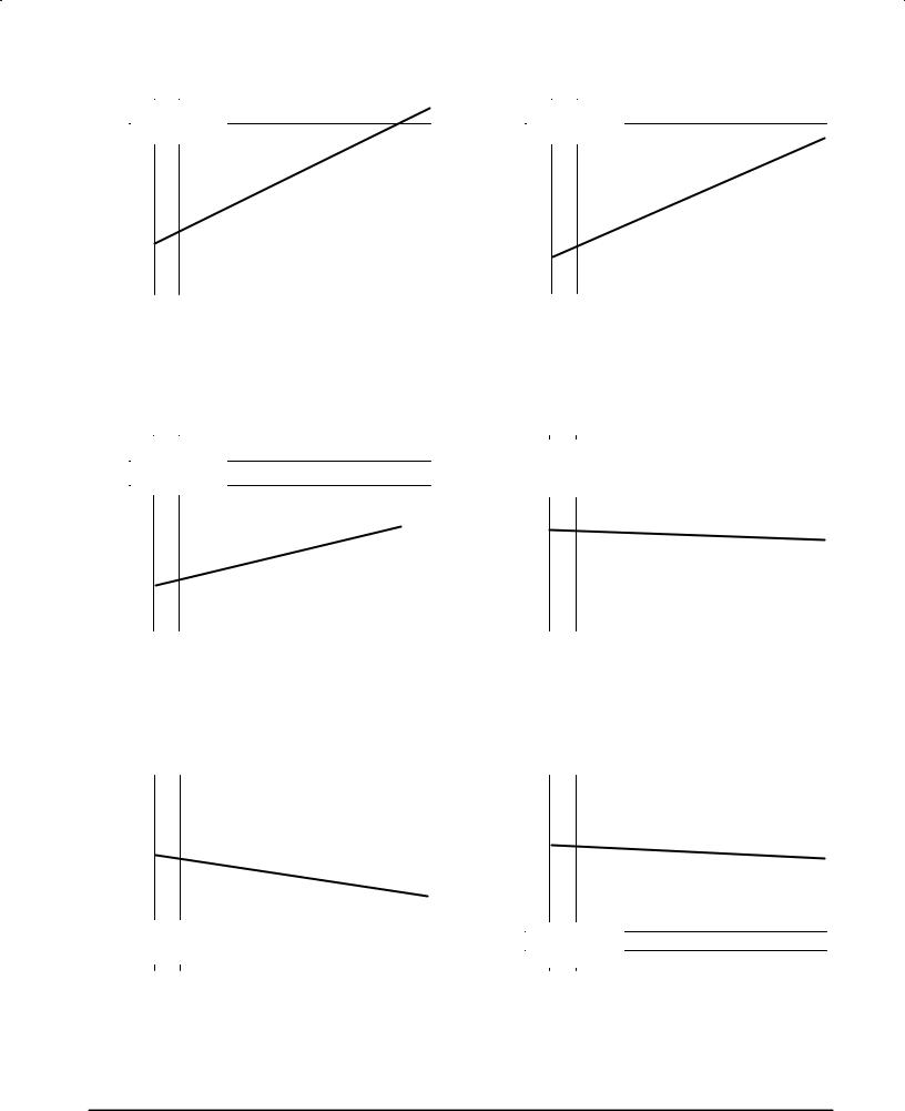
Figure 1. Quiescent Current versus Temperature
|
50 |
|
|
|
|
|
|
|
|
|
|
|
|
|
|
(μA) |
|
|
MC33466H±33JT1 |
|
|
|
|
|
|
|
|
|
|
|
|
|
|
|
|
|
|
|
|
|
|
|
|
|
|
||
|
|
IO = 0 mA |
|
|
|
|
|
|
|
|
|
|
|
||
CURRENT |
40 |
|
Vin = 2.0 V |
|
|
|
|
|
|
|
|
|
|
|
|
BIAS |
|
|
|
|
|
|
|
|
|
|
|
|
|
|
|
30 |
|
|
|
|
|
|
|
|
|
|
|
|
|
|
|
|
|
|
|
|
|
|
|
|
|
|
|
|
|
||
QUIESCENT, |
|
|
|
|
|
|
|
|
|
|
|
|
|
|
|
20 |
|
|
|
|
|
|
|
|
|
|
|
|
|
|
|
|
|
|
|
|
|
|
|
|
|
|
|
|
|
||
Q |
|
|
|
|
|
|
|
|
|
|
|
|
|
|
|
|
|
|
|
|
|
|
|
|
|
|
|
|
|
|
|
|
|
|
|
|
|
|
|
|
|
|
|
|
|
|
|
I |
|
|
|
|
|
|
|
|
|
|
|
|
|
|
|
|
10 |
|
|
|
|
|
|
|
|
|
|
|
|
|
|
|
|
±20 |
|
0 |
20 |
40 |
60 |
80 |
|||||||
|
±40 |
|
|||||||||||||
TA, AMBIENT TEMPERATURE (°C)
Figure 3. Oscillator Frequency versus Temperature
|
100 |
|
|
|
|
|
|
|
|
|
|
|
|
|
(kHz) |
|
|
MC33466H±50JT1 |
|
|
|
|
|
|
|
|
|
|
|
|
|
|
|
|
|
|
|
|
|
|
|
|
||
|
|
L = |
120 μH |
|
|
|
|
|
|
|
|
|
|
|
|
|
|
|
|
|
|
|
|
|
|
|
|
||
FREQUENCY |
80 |
|
IO = 10 mA |
|
|
|
|
|
|
|
|
|
|
|
|
Vin = 3.0 V |
|
|
|
|
|
|
|
|
|
|
|||
|
|
|
|
|
|
|
|
|
|
|
|
|||
OSCILLATOR, |
60 |
|
|
|
|
|
|
|
|
|
|
|
|
|
|
|
|
|
|
|
|
|
|
|
|
|
|
||
40 |
|
|
|
|
|
|
|
|
|
|
|
|
|
|
|
|
|
|
|
|
|
|
|
|
|
|
|
||
osc |
|
|
|
|
|
|
|
|
|
|
|
|
|
|
|
|
|
|
|
|
|
|
|
|
|
|
|
|
|
|
|
|
|
|
|
|
|
|
|
|
|
|
|
|
f |
|
|
|
|
|
|
|
|
|
|
|
|
|
|
|
20 |
|
|
|
|
|
|
|
|
|
|
|
|
|
|
±40 |
±20 |
0 |
20 |
40 |
60 |
80 |
|||||||
TA, AMBIENT TEMPERATURE (°C)
Figure 5. Lx Switching Current versus Temperature
(mA) |
200 |
|
|
|
|
|
|
|
|
|
|
|
|
|
|
|
|
|
|
|
|
|
|
|
|
|
|
|
|
||
160 |
|
|
|
|
|
|
|
|
|
|
|
|
|
|
|
|
|
|
|
|
|
|
|
|
|
|
|
|
|
||
CURRENT |
|
|
|
|
|
|
|
|
|
|
|
|
|
|
|
|
|
|
|
|
|
|
|
|
|
|
|
|
|
||
120 |
|
|
|
|
|
|
|
|
|
|
|
|
|
|
|
|
|
|
|
|
|
|
|
|
|
|
|
|
|
||
SWITCHINGLx, |
|
|
|
|
|
|
|
|
|
|
|
|
|
|
|
|
|
|
|
|
|
|
|
|
|
|
|
|
|
||
40 |
|
|
MC33466H±50JT1 |
|
|
|
|
|
|
|
|
|
|
||
Lx |
80 |
|
|
|
|
|
|
|
|
|
|
|
|
|
|
|
|
|
|
|
|
|
|
|
|
|
|
|
|
|
|
|
|
I |
O |
= 10 mA |
|
|
|
|
|
|
|
|
|
|
|
I |
|
|
|
|
|
|
|
|
|
|
|
|
|
|
|
|
0 |
|
Vin = 2.0 V |
|
|
|
|
|
|
|
|
|
|
||
|
±40 |
|
|
±20 |
0 |
20 |
40 |
60 |
80 |
||||||
TA, AMBIENT TEMPERATURE (°C)
Figure 2. Quiescent Current versus Temperature
|
2.0 |
|
|
|
|
|
|
|
|
|
|
|
|
|
|
(μA) |
|
|
MC33466H±33JT1 |
|
|
|
|
|
|
|
|
|
|
|
|
|
|
|
|
|
|
|
|
|
|
|
|
|
|
||
|
|
IO = 0 mA |
|
|
|
|
|
|
|
|
|
|
|
||
CURRENT |
1.6 |
|
Vin = 5.5 V |
|
|
|
|
|
|
|
|
|
|
|
|
BIAS |
|
|
|
|
|
|
|
|
|
|
|
|
|
|
|
1.2 |
|
|
|
|
|
|
|
|
|
|
|
|
|
|
|
|
|
|
|
|
|
|
|
|
|
|
|
|
|
||
QUIESCENT, |
|
|
|
|
|
|
|
|
|
|
|
|
|
|
|
0.8 |
|
|
|
|
|
|
|
|
|
|
|
|
|
|
|
|
|
|
|
|
|
|
|
|
|
|
|
|
|
||
Q |
|
|
|
|
|
|
|
|
|
|
|
|
|
|
|
|
|
|
|
|
|
|
|
|
|
|
|
|
|
|
|
|
|
|
|
|
|
|
|
|
|
|
|
|
|
|
|
I |
|
|
|
|
|
|
|
|
|
|
|
|
|
|
|
|
0.4 |
|
|
|
|
|
|
|
|
|
|
|
|
|
|
|
|
±20 |
|
0 |
20 |
40 |
60 |
80 |
|||||||
|
±40 |
|
|||||||||||||
TA, AMBIENT TEMPERATURE (°C)
Figure 4. Maximum Duty Ratio
versus Temperature
|
100 |
|
|
|
|
|
|
|
|
|
|
|
|
|
(%) |
|
|
MC33466H±50JT1 |
|
|
|
|
|
|
|
|
|
|
|
|
|
|
|
|
|
|
|
|
|
|
|
|
||
|
|
|
|
|
|
|
|
|
|
|
|
|
|
|
|
|
L = |
120 μH |
|
|
|
|
|
|
|
|
|
|
|
RATIO |
|
|
|
|
|
|
|
|
|
|
|
|
||
|
|
Vin |
= 3.0 V |
|
|
|
|
|
|
|
|
|
|
|
|
90 |
|
IO = 10 mA |
|
|
|
|
|
|
|
|
|
|
|
DUTY |
|
|
|
|
|
|
|
|
|
|
|
|
|
|
80 |
|
|
|
|
|
|
|
|
|
|
|
|
|
|
|
|
|
|
|
|
|
|
|
|
|
|
|
||
, MAXIMUM |
|
|
|
|
|
|
|
|
|
|
|
|
|
|
|
|
|
|
|
|
|
|
|
|
|
|
|
||
70 |
|
|
|
|
|
|
|
|
|
|
|
|
|
|
|
|
|
|
|
|
|
|
|
|
|
|
|
||
max |
|
|
|
|
|
|
|
|
|
|
|
|
|
|
|
|
|
|
|
|
|
|
|
|
|
|
|
|
|
D |
60 |
|
|
|
|
|
|
|
|
|
|
|
|
|
|
|
|
|
|
|
|
|
|
|
|
|
|
|
|
|
±40 |
±20 |
0 |
20 |
40 |
60 |
80 |
|||||||
TA, AMBIENT TEMPERATURE (°C)
Figure 6. VLx Voltage Limit versus Temperature
(V) |
1.0 |
|
|
|
|
|
|
|
|
|
|
|
|
|
|
|
|
|
|
|
|
|
|
|
|
||
0.9 |
|
|
|
|
|
|
|
|
|
|
|
|
|
|
|
|
|
|
|
|
|
|
|
|
|
||
LIMIT |
|
|
|
|
|
|
|
|
|
|
|
|
|
|
|
|
|
|
|
|
|
|
|
|
|
|
|
|
|
|
|
|
|
|
|
|
|
|
|
|
|
VOLTAGE |
0.8 |
|
|
|
|
|
|
|
|
|
|
|
|
|
|
|
|
|
|
|
|
|
|
|
|
|
|
Lx |
0.7 |
|
|
|
|
|
|
|
|
|
|
|
|
|
|
|
|
|
|
|
|
|
|
|
|
||
|
|
|
|
|
|
|
|
|
|
|
|
||
|
|
|
|
|
|
|
|
|
|
|
|
|
|
, V |
|
|
|
|
|
|
|
|
|
|
|
|
|
|
|
|
|
|
|
|
|
|
|
|
|
|
|
LxLim |
0.6 |
|
MC33466H±50JT1 |
|
|
|
|
|
|
|
|
|
|
V |
|
|
IO = 10 mA |
|
|
|
|
|
|
|
|
|
|
|
|
|
|
|
|
|
|
|
|
|
|
|
|
|
0.5 |
|
Vin = 2.0 V |
|
|
|
|
|
|
|
|
|
|
|
±40 |
±20 |
0 |
20 |
40 |
60 |
80 |
||||||
TA, AMBIENT TEMPERATURE (°C)
4 |
MOTOROLA ANALOG IC DEVICE DATA |
 Loading...