


SPLIT-TYPE AIR CONDITIONERS
No. OB228
SERVICE MANUAL
Wireless type
Models
MS-18NV - E4 (WH) · MU-18NV - E4
CONTENTS
|
1. TECHNICAL CHANGES ····································2 |
||
|
2. PART NAMES AND FUNCTIONS······················2 |
||
|
3. SPECIFICATION·················································4 |
||
|
4. OUTLINES AND DIMENSIONS ·························5 |
||
|
5. WIRING DIAGRAM ············································6 |
||
MS-18NV - E4 |
6. REFRIGERANT SYSTEM DIAGRAM ················7 |
||
7. PERFORMANCE CURVES ································8 |
|||
|
|||
|
8. MICROPROCESSOR CONTROL ····················10 |
||
|
9. SERVICE FUNCTIONS ····································16 |
||
|
10. |
TROUBLESHOOTING······································18 |
|
|
11. DISASSEMBLY INSTRUCTIONS·····················24 |
||
|
12. |
PARTS LIST··················································· ···28 |
|
|
13. |
OPTIONAL PARTS···········································31 |
|

1 
 TECHNICAL CHANGES
MS-18NV - E3 MS-18NV - E4
1. Indoor electronic control P.C. board has changed.
MU-18NV - E3 MU-18NV - E4
1.Compressor has changed.(NH-33VMDT PH-33VPET)
2.Outdoor heat exchanger has changed.
3.Refrigerant filling capacity(R-22) has changed.(1.65kg 1.05kg)
2 
 PART NAMES AND FUNCTIONS
INDOOR UNIT
MS-18NV - E4
Grille
Air cleaning filter(option)
Deodorizing filter(option)
Remote control receiving section
(When the grille is open)
2

OUTDOOR UNIT
MU-18NV - E4
REMOTE CONTROLLER
MS-18NV - E4
Signal transmitting section
Operation display section
OPERATE /STOP (ON /OFF)button
OPERATION SELECT button
FAN SPEED CONTROL button
SLEEP button
ON-TIMER button
CLOCK SET button
HR. button MIN. button (TIME SET button)
TEMPERATURE buttons
VANE CONTROL button SWING buttons
OFF-TIMER button RESET button
3
|
3 |
|
|
SPECIFICATION |
|
|
|
|
||||
|
|
|
|
|
|
|
|
|
|
|
|
|
|
|
|
|
|
|
|
|
|
|
|
|
|
|
|
|
|
|
|
Model |
|
|
|
MS-18NV - |
|
|
|
|
|
|
|
|
|
|
|
E4 |
|
||
|
|
|
|
|
|
|
|
|
|
|
|
|
|
|
|
|
|
|
Function |
|
|
|
Cooling |
||
|
|
|
|
|
|
Power supply |
|
Single phase, 220-240V, 50Hz |
||||
|
|
|
|
|
Capacity |
|
|
kW |
5.1 |
|
|
|
|
|
Capacity |
Dehumidification |
|
|
R/h |
2.5 |
|
|
|||
|
|
|
|
|
Air flow(Hi) |
|
|
K /h |
INDOOR 756 / OUTDOOR 2340-2400 |
|||
|
|
|
|
|
Power outlet |
|
|
A |
15 |
|
|
|
|
|
|
|
|
Running current |
|
|
A |
9.1 |
|
|
|
|
|
|
|
|
Power input |
|
|
W |
1,910-2,010 |
|
||
|
Electrical data |
Auxiliary heater |
|
|
A(kW) |
— |
||||||
|
Power factor |
|
|
% |
95-92 |
|
|
|||||
|
|
|
|
|
|
|
|
|
||||
|
|
|
|
|
Starting current |
|
|
A |
51-55 |
|
|
|
|
|
|
|
|
Compressor motor current |
A |
8.46 |
|
|
|||
|
|
|
|
|
Fan motor current |
A |
INDOOR 0.25 / OUTDOOR 0.39 |
|||||
|
Coefficient of performance(C.O.P) |
|
|
|
2.67-2.54 |
|
||||||
|
|
|
|
|
Model |
|
|
|
PH-33VPET |
|||
|
Compressor |
|
|
|
|
|
|
|
||||
|
Output |
|
|
W |
1,500 |
|
|
|||||
|
|
|
|
|
|
|
|
|
|
|
||
|
|
|
|
|
Winding resistance(at20:) |
" |
C-R1.08 C-S 2.18 |
|||||
|
|
|
Indoor |
Model |
|
|
|
RA4V27-EA or EF |
||||
|
|
fan motor |
Winding resistance(at20:) |
" |
WHT-BLK183.8 BLK-RED250.5 |
|||||||
|
|
Outdoor |
Model |
|
|
|
RA6V50-OF or OG |
|||||
|
|
fan motor |
Winding resistance(at20:) |
" |
WHT-BLK116.4 BLK-RED111 |
|||||||
|
|
|
|
|
|
|
|
Width |
mm |
1,015 |
|
|
|
|
|
|
|
Indoor unit |
|
Height |
mm |
320 |
|
|
|
|
Dimensions |
|
|
|
Depth |
mm |
190 |
|
|
|||
|
|
|
|
Width |
mm |
850 |
|
|
||||
|
|
|
|
|
|
|
|
|
|
|||
|
|
|
|
|
Outdoor unit |
|
Height |
mm |
605 |
|
|
|
|
|
|
|
|
|
|
|
Depth |
mm |
290 |
|
|
|
|
Weight |
Indoor unit |
|
|
kg |
14 |
|
|
|||
|
|
Outdoor unit |
|
|
kg |
48 |
|
|
||||
|
|
|
|
|
|
|
|
|
||||
|
|
|
|
|
|
|
|
|
|
|
|
|
|
|
|
|
|
Air direction |
|
|
|
5 |
|
|
|
|
|
|
|
|
|
|
|
|
|
|
|
|
|
|
|
|
|
Sound level |
|
Indoor unit |
dB |
42 |
|
|
|
|
|
|
|
|
(Hi) |
|
|
Outdoor unit |
dB |
52 |
|
|
|
|
|
|
|
Fan speed |
|
Indoor unit |
rpm |
1,180 |
|
|
|
|
|
|
|
|
|
|
|
|
|
|
|
|
|
|
|
|
|
(Hi) |
|
|
Outdoor unit |
rpm |
830-860 |
|
|
|
Special remarks |
|
|
|
|
|
|
|
||||
|
Fan speed |
|
Indoor unit |
|
4 |
|
|
|||||
|
|
|
|
|
|
|
|
|
|
|
|
|
|
|
|
|
|
regulator |
|
Outdoor unit |
|
1 |
|
|
|
|
|
|
|
|
|
|
|
|
|
|
||
|
|
|
|
|
Refrigerant filling capacity(R-22) |
kg |
1.05 |
|
|
|||
|
|
|
|
|
|
|
|
|
|
|
|
|
|
|
|
|
|
Refrigerating oil |
(Model) |
cc |
900 (MS32N1) |
||||
|
|
|
|
|
|
|
|
|
|
|
|
|
|
|
|
|
|
Thermistor |
|
RT11(at25:) |
k" |
10 |
|
|
|
|
|
|
|
|
|
RT12(at25:) |
k" |
10 |
|
|
||
|
|
|
|
|
|
|
|
|
|
|||
|
NOTE:Test conditions |
|
|
|
|
|
|
|
||||
|
|
|
Cooling : Indoor |
DB27: / WB19: |
|
|
|
|
||||
|
|
|
|
Outdoor |
DB35: / WB24: |
|
|
|
|
|||
4

4 
 OUTLINES AND DIMENSIONS
MS-18NV - E4
INDOOR UNIT
995
4holes 11o20
150 |
648 |
60 |
40 |
450
450
438
Unit : mm
Indoor unit
217
|
20 |
254 |
297 |
3 |
352
Installation plate
1015
190
320 |
|
|
|
Air in |
|
|
|
|
|
50 |
775 |
|
190 |
Air out |
|
|
|
|
|
|
|
17.5 |
|
Power supply cord |
|
56 |
|
Lead to right 2m |
|
|
|
|
||
|
|
|
|
Lead to left 1m |
|
160 |
|
|
|
Wireless remote controller
MU-18NV - E4
OUTDOOR UNIT
Wall hole [75
5
Installation plate
Liquid line [8-0.5m {Gas line [12-0.43m Insulation [50 O.D
[28 I.D
Drain hose [16
Insulation [28
If the front or right/left sides are vacant, the top has only to be 10cm unobstructed.
If the right/left sides or back side is vacant,the front has only to be 50cm unobstructed.
5
5 
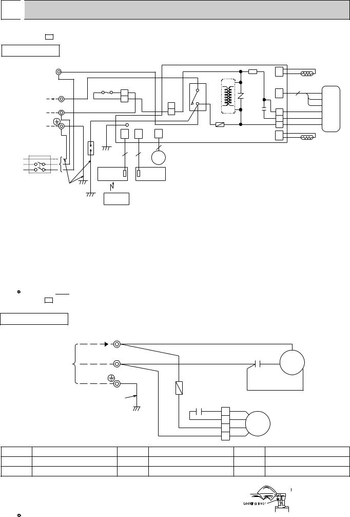
 WIRING DIAGRAM
MS-18NV - E4 |
MODEL WIRING DIAGRAM |
INDOOR UNIT
L |
TB |
BRN |
|
|
|
|
|
|
|
|
|
|
|
w |
|
|
|
|
|
|
|
CN |
|
RT12 |
|||
TO OUTDOOR |
BRN |
|
|
|
|
|
|
HIC1 |
IC141 |
112 |
|
||
UNIT |
|
|
|
|
|
|
|
|
|
|
|||
CONNECTING |
w |
F12 |
BLU |
|
|
|
|
w |
|
|
3 |
|
|
|
|
|
|
|
|
|
|
BRN |
|
||||
220-240V~ |
2 |
2 |
|
|
|
4 |
NR11 |
CN |
|
||||
WHT |
BLU |
|
|
CN201 |
w 3 52C |
121 |
|
YLW |
|
||||
|
w |
1 |
|
|
|
|
|
||||||
|
N w |
|
|
|
|
|
3 |
|
CN211 |
|
GRY |
|
|
|
|
|
|
|
BLU |
|
C11 |
|
|
||||
|
BLU |
|
|
|
TRANS |
|
WHT |
MF |
|||||
|
|
|
|
1 |
4 |
|
|||||||
|
BLU |
BRN |
|
|
|
|
F11 |
|
2 |
|
RED |
|
|
|
|
|
|
|
|
|
BLK |
|
|||||
|
|
|
GRN/YLW |
|
LD1 |
|
|
|
|
1 |
|
|
|
POWER |
|
|
|
|
|
|
|
|
|
|
|||
|
|
CN |
CN |
CN |
|
|
|
|
|
|
|
||
SUPPLY |
|
|
ELECTRONIC CONTROL P.C BOARD |
CN |
|
RT11 |
|||||||
CORD |
|
DSAR |
101 |
102 |
151 |
111 |
|
||||||
~/N 220-240V |
|
|
|
5 |
|
|
|
|
|
|
|||
50Hz |
|
|
|
|
|
|
|
|
|
|
|||
|
|
|
3 |
3 |
|
|
|
|
|
|
|
||
|
|
|
|
|
|
MV |
|
|
|
|
|
|
|
|
|
RECEIVER |
|
|
DISPLAY |
|
|
|
|
|
|
|
|
CIRCUITBREAKER |
P.C.BOARD |
|
P.C.BOARD |
|
|
|
|
|
|
||||
GRN/YLW |
|
|
|
|
|
|
|
|
|
|
|
||
|
|
|
REMOTE |
|
|
|
|
|
|
|
|
|
|
|
|
|
CONTROLLER |
|
|
|
|
|
|
|
|
|
|
SYMBOL |
NAME |
SYMBOL |
NAME |
SYMBOL |
NAME |
|
|
|
|
|
|
C11 |
INDOOR FAN CAPACITOR |
IC141 |
HYBRID IC |
RT12 |
INDOOR COIL THERMISTOR |
|
|
|
|
|
|
DSAR |
SURGE ABSORBER |
MF |
INDOOR FAN MOTOR |
TB |
TERMINAL BLOCK |
|
|
|
|
|
|
F11 |
FUSE(3.15A) |
MV |
VANE MOTOR |
52C |
CONTACTOR |
|
|
|
|
|
|
F12 |
THERMAL FUSE(93¡C) |
NR11 |
VARISTOR |
|
|
HIC1 |
DC / DC CONVERTER |
RT11 |
ROOM TEMPERATURE THERMISTOR |
|
|
NOTE:1. For the outdoor electric wiring refer to the outdoor unit electric wiring diagram for servicing.
2.Use copper conductors only.(For field wiring)
3.Symbols below indicate.
:Terminal block,


 : Connector
MU-18NV - E4
OUTDOOR UNIT MODEL WIRING DIAGRAM
|
220-240V~ |
TB |
|
|
|
|
|
|
2 |
w |
|
WHT |
|
|
|
|
|
WHT |
|
|
|
C |
|
FROM |
|
|
C1 |
|
|
||
N |
w |
BLU |
RED |
MC |
|||
INDOOR UNIT |
|
||||||
|
|
|
|
S |
|||
CONNECTING |
|
|
|
|
R |
||
|
|
|
|
|
|||
|
|
F |
|
|
BLK |
|
GRN/YLW
C2
RED RED
ORN 1 ORN
WHT 2 WHT MF
BLU 3 BLK
|
|
|
4 |
|
|
SYMBOL |
NAME |
SYMBOL |
NAME |
SYMBOL |
NAME |
C1 |
COMPRESSOR CAPACITOR |
F |
FUSE(2A) |
MF |
OUTDOOR FAN MOTOR(INNER THEMOSTAT) |
C2 |
OUTDOOR FAN CAPACITOR |
MC |
COMPRESSOR(INNER THERMOSTAT) |
TB |
TERMINAL BLOCK |
NOTE:1. Use copper conductors only.(For field wiring)
2.“w”show the terminals with a lock mechanism, so they cannot be removed when you pull the lead wire.
Be sure to pull the wire by pushing the locking lever(projected part) of the terminal with a finger.
3.Symbols below indicate.
: Terminal block, |
|
|
|
|
: Connector |
1.Slide the sleeve. 


 2.Pull the wire while
pushing the locking lever.
6
6 
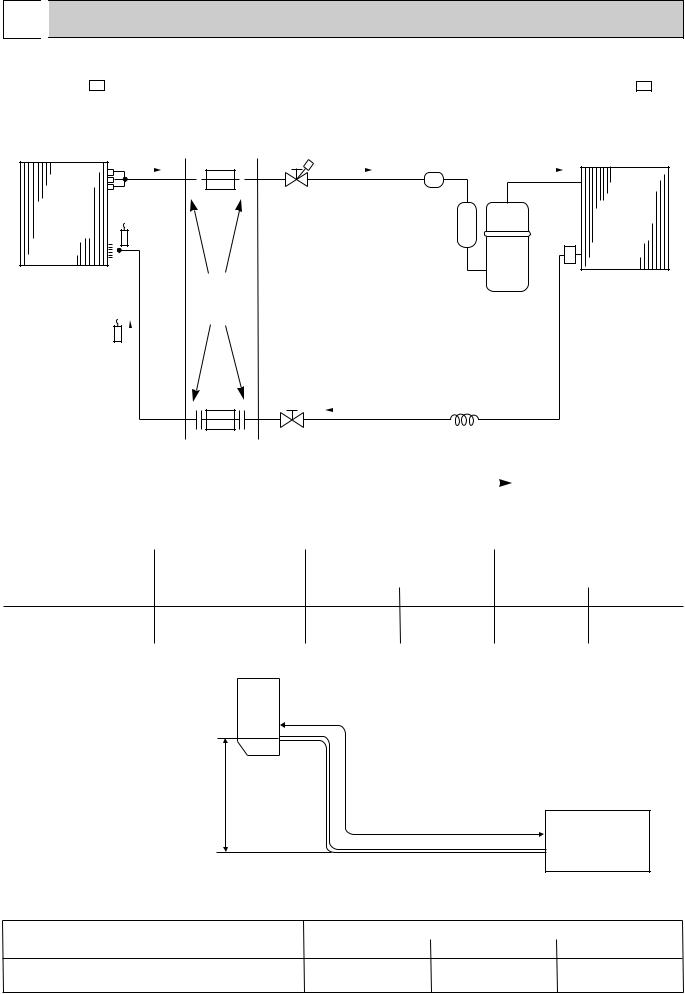
 REFRIGERANT SYSTEM DIAGRAM
MS-18NV - E4 |
|
Unit:mm |
|
MU-18NV - E4 |
|
INDOOR UNIT |
Refrigerant pipe [15.88 |
OUTDOOR UNIT |
|
|
|
|
(Option) |
|
|
(with heat insulator) |
|
|
|
|
|
|
|
|
|
|
|
|
|
|
|
|
|
|
|
|
|
|
Accumulator |
|
|
|
|
|
|
|
|
|
|
|
|
|
|
|
|
|
|
|
|
|
|
|
|
|
|
|
|
|
|
|
|
||
|
|
|
|
|
|
|
|
|
|
|
|
|
|
|
|
|
|
|
|
|
|
|
|
|
|
|
|
|
|
|
|
Indoor coil |
Stop valve |
|
|
|
|
|
|
|
|||||||||||||||
|
Indoor |
|
|
|
|
|
|
|
|
||||||||||||||||||
|
|
|
|
|
|
|
|
Outdoor |
|||||||||||||||||||
|
heat |
|
|
thermistor |
(with service port) |
|
|
|
|
|
heat |
|
|||||||||||||||
|
|
|
|
|
|
|
|
RT12 |
|
|
|
|
|
|
|||||||||||||
|
exchanger |
|
|
|
|
|
|
|
|
|
|
|
|
|
|
|
|
Strainer |
exchanger |
|
|||||||
|
|
|
|
|
|
|
|
|
|
|
|
|
|
|
|
|
|
|
|
|
|
|
|
||||
|
|
|
|
|
|
|
|
|
|
|
|
|
|
|
|
|
|
|
|
|
|
|
|
|
|
||
|
|
|
|
|
|
|
|
|
|
|
|
|
|
|
|
|
|
|
|
|
|
|
|
|
|
|
|
|
|
|
|
|
|
|
|
|
|
|
|
|
|
|
|
|
|
|
|
|
|
|
|
|
|
|
|
|
Distributor |
|
Flared |
|
|
|
|
|
|
|
|
|
|
|
|
|
|||||||||||
|
|
|
|
|
|
|
|
|
|
|
|
|
|
|
|
|
|
|
|
|
|
|
|||||
|
|
|
|
|
|
|
|
|
|
connection |
|
|
|
|
|
|
|
Compressor |
|
|
|||||||
|
|
|
|
|
|
|
|
|
|
|
|
|
|
|
|
|
|
|
|
|
|
|
|
||||
|
|
|
|
|
|
|
|
|
|
|
|
|
|
|
|
|
|
|
|
|
|
|
|
|
|
||
Room temperature |
|
|
|
|
|
|
|
|
|
|
|
|
|
|
|
|
|
|
|
|
|
||||||
|
|
|
|
|
|
|
|
|
|
|
|
|
|
|
|
|
|
|
|
||||||||
thermistor |
|
|
|
|
|
|
|
|
|
|
|
|
|
|
|
|
|
|
Capillary tube |
|
|
||||||
RT11 |
|
|
|
|
|
|
|
|
|
|
|
|
|
|
|
|
|
|
|
|
|||||||
|
|
|
|
|
|
|
|
|
|
|
|
Stop valve |
[3.0X[2.0X700 |
|
|
||||||||||||
|
|
|
|
|
|
|
|
|
|
|
|
|
|
|
|
|
|||||||||||
|
|
|
|
|
|
|
|
|
|
|
|
|
|
|
|
|
|
|
|
|
|||||||
|
|
|
|
|
|
|
|
|
|
Refrigerant pipe [6.35 |
|
|
|
|
|
|
|
||||||||||
|
|
|
|
|
|
|
|
|
|
(Option) |
|
|
|
|
|
|
|
|
|
|
|
|
|
||||
|
|
|
|
|
|
|
|
|
|
(with heat insulator) |
|
|
Refrigerant flow in cooling |
||||||||||||||
MAX. REFRIGERANT PIPING LENGTH |
|
|
|||||||||||||||||||||||||
|
|
|
|
|
|
|
|||||||||||||||||||||
|
|
|
|
|
|
|
|
|
|
|
|
|
|
|
|
|
|
|
|||||||||
|
|
|
|
|
|
|
|
|
|
Refrigerant piping |
|
|
Length of connecting pipe : m |
||||||||||||||
|
Model |
|
|
|
|
|
|
|
|
|
|
|
|
|
|
Piping size O.D : mm |
|
||||||||||
|
|
|
|
|
|
|
|
Max. length : m |
|
|
|
|
|
|
|
||||||||||||
|
|
|
|
|
|
|
|
|
|
|
|
A |
|
|
Gas |
Liquid |
|
Indoor unit |
Outdoor unit |
||||||||
MS-18NV - |
|
|
|
|
|
|
15 |
|
|
15.88 |
6.35 |
|
Gas 0.43 |
Gas 0 |
|||||||||||||
E4 |
|
|
|
|
Liquid 0.5 |
Liquid 0 |
|||||||||||||||||||||
|
|
|
|
|
|
|
|
|
|
|
|
|
|
|
|
|
|
|
|
|
|
|
|||||
|
|
|
|
|
|
|
|
|
|
|
|
|
|
|
|
|
|
|
|
|
|
|
|
|
|
|
|
MAX. HEIGHT DIFFERENCE
Indoor unit
|
Refrigerant Piping |
w Max. Height |
Max.length |
difference 5m |
A |
|
Outdoor unit
wHeight difference should be within 5m regardless of which unit, indoor or outdoor position is high.
ADDITIONAL REFRIGERANT CHARGE(R-22 : g)
Model |
Outdoor unit precharged |
|
Refrigerant piping length (one way) |
|
|||
|
|
|
|||||
7m |
10m |
15m |
|||||
|
|
|
|
||||
MS-18NV - |
|
|
1050 |
0 |
45 |
120 |
|
E4 |
|
||||||
|
|
|
|
|
|
|
|
Calculation : Xg=15g/mO(A-7)m
7

7 
 PERFORMANCE CURVES
MS-18NV - E4
The standard data contained in these specifications apply only to the operation of the air conditioner under normal conditions. Since operating conditions vary according to the areas where these units are installed. The following information has been provided to clarify the operating characteristics of the air conditioner under the conditions indicated by the performance curve.
(1) GUARANTEED VOLTAGE
Rated voltage : ±10% (198 ~ 264V),50Hz
(2) AIR FLOW
Air flow should be set at MAX.
(3) MAIN READINGS
(1) |
Indoor intake air wet-bulb temperature |
:°CWB |
} |
Cooling |
(2) |
Indoor outlet air wet-bulb temperature |
:°CWB |
||
(3) |
Outdoor intake air dry-bulb temperature |
:°CDB |
|
|
(4) Total input |
:W |
|
|
|
Indoor air wet-bulb temperature difference on the left side of the chart on next page shows the difference between the indoor intake air wet-bulb temperature and the indoor outlet air wet-bulb temperature for your reference at service.
How to measure the indoor air wet-bulb temperature difference
1.Attach at least 2 sets of wet-and dry-bulb thermometers to the indoor air intake as shown in the figure, and at least 2 sets of wet-and dry-bulb thermometers to the indoor air outlet. The thermometers must be attached to the position where air speed is high.
2.Attach at least 2 sets of dry-bulb thermometers to the outdoor air inlet. Cover the thermometers to prevent direct rays of the sun.
3.Check that the air filter is cleaned.
4.Open windows and doors of room.
5.Press the EMERGENCY OPERATION switch to start the EMERGENCY operation.
6.When system stabilizes after more than 15 minutes, measure temperature and take an average temperature.
7.10 minutes later, measure temperature again and check that the temperature does not change.
INDOOR UNIT |
OUTDOOR UNIT |
Wet and dry-bulb |
Dry-bulb |
thermometers |
|
|
thermometers |
8

MS-18NV - E4
OUTDOOR LOW PRESSURE AND OUTDOOR UNIT CURRENT COOL operation
1 Both indoor and outdoor unit are under the same temperature/humidity condition.
Dry-bulb temperature |
Relative humidity(%) |
|
|
20 |
50 |
|
|
25 |
60 |
|
|
30 |
70 |
|
|
2 Air flow should be set at MAX.
3The unit of pressure has been changed to MPa on the international system of units(SI unit system). The conversion factor is : 1(MPa • G) =10.2(kgf/f • G)
(kgf/F•G)(MPa•G) |
MU-18NV - |
|
|
||||||||||||
E4 |
|||||||||||||||
pressure |
7 |
0.7 |
|
|
|
|
|
|
|
|
|
|
|||
|
0.6 |
|
|
|
|
|
|
|
|
|
|
||||
6 |
|
|
|
|
|
|
|
|
|
|
|
||||
|
|
|
|
|
|
|
|
|
|
|
|
||||
|
|
|
|
|
|
|
|
220V/240V |
|
|
|
|
|
||
|
|
|
|
|
|
|
|
|
|
|
|
|
|
||
low |
5 |
|
|
|
0.5 |
|
|
|
|
|
|
|
|
|
|
Outdoor |
|
|
|
|
|
|
|
|
|
|
|
|
|||
|
|
0.4 |
|
|
|
|
|
|
|
|
|
|
|||
4 |
|
|
|
|
|
|
|
|
|
|
|
|
|||
|
|
|
|
|
|
|
|
|
|
|
|
|
|||
|
|
0.3 |
|
|
|
|
|
|
|
|
|
|
|||
|
3 |
|
|
|
|
|
|
|
|
|
|
|
|||
|
|
|
|
|
|
|
|
|
|
|
|||||
|
15 |
18 20 |
25 |
30 32 35(:) |
|||||||||||
|
|
||||||||||||||
|
|
|
|
|
|
|
50 |
60 |
70(%) |
|
|||||
Ambient temperature(˚C)Ambient humidity(%)
Outdoor unit current(A)
MU-18NV - E4
11 |
|
|
|
|
|
|
|
|
|
|
|
|
|
|
|
|
|
|
|
10 |
|
|
|
|
|
|
|
|
|
|
|
|
|
|
|
|
|
|
|
9 |
|
|
|
|
|
|
|
|
|
|
|
|
|
|
|
|
|
|
|
|
|
|
|
|
|
|
|
|
|
8 |
|
|
|
|
220V/240V |
|
|
||
|
|
|
|
|
|
|
|
|
|
7 |
|
|
|
|
|
|
|
|
|
|
|
|
|
|
|
|
|
|
|
6 |
|
|
|
|
|
|
|
|
|
|
|
|
|
|
30 32 35(:) |
||||
15 18 20 |
25 |
||||||||
50 |
60 |
70(%) |
|
||||||
Ambient temperature(˚C)Ambient humidity(%)
9
8 
 MICROPROCESSOR CONTROL
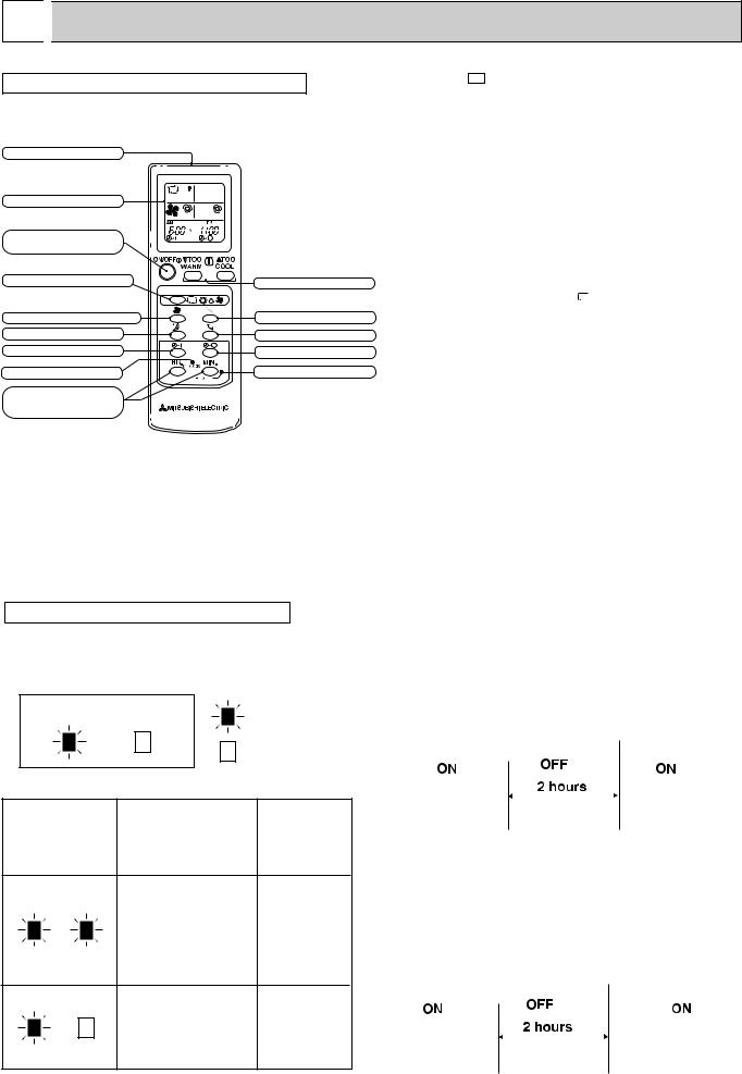
WIRELESS REMOTE CONTROLLER
Signal transmitting section |
|
Operation display section |
|
OPERATE /STOP |
|
(ON /OFF)button |
|
OPERATION SELECT button |
TEMPERATURE buttons |
|
|
FAN SPEED CONTROL button |
VANE CONTROL button |
SLEEP button |
SWING buttons |
ON-TIMER button |
OFF-TIMER button |
CLOCK SET button |
RESET button |
HR. button |
|
MIN. button |
|
(TIME SET button) |
|
MS-18NV - E4
Once the operation mode are set, the same operation mode can be repeated by simply turning the OPERATE/STOP(ON/OFF) button ON.
Indoor unit receives the signal with a beep tone.
When the system turns off, 3-minute time delay will operate to protect system from overload and compressor will not restart for 3 minutes.
8-1. “I FEEL CONTROL” ( 
 ) OPERATION
(1)Press OPERATE/STOP(ON/OFF) button on the remote controller. Operation Indicator lamp of the indoor unit turns on with a beep tone.
(2)Select “I FEEL CONTROL”( ) mode with the OPERATION SELECT button.
(3)The operation mode is determined by the room temperature at start-up of the operation.
Initial room temperature |
mode |
|
25: or more |
COOL mode of |
|
“I FEEL CONTROL“ |
||
|
||
more than 13:, |
DRY mode of |
|
less than 25: |
“I FEEL CONTROL” |
|
|
|
INDOOR UNIT DISPLAY SECTION
Operation Indicator lamp
The operation indicator at the right side of the indoor unit indicates the operation state.
Operation Indicator |
lighting |
not lighting
●Once the mode is fixed, the mode does not change by room temperature afterwards.
●Under the ON-TIMER (  ) operation, the mode is determined according to the room temperature as the operation starts.
●When the system is stopped with the
OPERATE/STOP(ON/OFF) button on the remote controller, and restarted within 2 hours in “I FEEL CONTROL” ( 
 ) mode, the system operates in previous mode automatically regardless of the room temperature.
Example |
|
|
|
||
Previous operation |
|
Restart |
|||
COOL mode of |
|
COOL mode of |
|||
“I FEEL CONTROL” or |
|
“I FEEL CONTROL” |
|||
COOL mode |
|
|
|
||
|
|
|
|
|
|
|
|
|
|
|
|
Difference betweeen set
Indication Operation state temperature and room temperature
This shows that the air conditioner is operating to reach
the target temperature.
About 2 :
Please wait unitil the target temperature is obtained.
or more
This shows that the |
|
room temperature is |
About 2 : |
approaching the |
or less |
target temperature. |
|
When the system is restarted after 2 hours and more, the operation mode is determined by the room temperature at start-up of the operation.
Example |
Restart |
||||
|
|
|
|
COOL or DRY mode of |
|
Previous operation |
“I FEEL CONTROL” that |
||||
COOL mode of |
determined by room |
||||
“I FEEL CONTROL” |
temperature at start-up |
||||
or COOL mode |
of the operation. |
||||
|
|
|
|
|
|
|
|
|
|
|
|
|
|
|
|
|
|
10
 Loading...