


SG79Y756H01
English
|
|
|
|
|
SPLIT-TYPE AIR CONDITIONERS |
HFC |
|
|
|
|
|
|
Models |
|
utilized |
|
|
|
|
|
MS-GA50VB |
Series |
R410A |
|
|
|
|||||
|
|
|
|
|
MSH-GA50VB |
When installing an MXZ series |
|
|
|
|
|
|
|||
|
|
|
|
|
|
||
|
|
|
|
|
[FLARE CONNECTION TYPE] |
||
|
|
|
|
|
outdoor unit, refer to the MS |
||
INSTALLATION MANUAL |
|
and MSH type manual for |
|||||
indoor unit set up.
IMPORTANT NOTES
TO COMPLY WITH THE REQUIREMENT OF AUSTRALIAN STANDARD AS/NZS 3000 ELECTRICAL INSTALLATIONS (Wiring Rules), THE ELECTRICAL WIRING REQUIRED BETWEEN THE INDOOR AND OUTDOOR UNITS MUST BE INSTALLED BYALICENCED ELECTRICAL CONTRACTOR.
1.THE FOLLOWING SHOULD ALWAYS BE OBSERVED FOR SAFETY
•Be sure to read “THE FOLLOWING SHOULD ALWAYS BE OBSERVED FOR SAFETY” before installing the air conditioner.
•Be sure to observe the cautions specifi ed here as they include important items related to safety.
•The indications and meanings are as follows.
 WARNING
Could lead to death, serious injury, etc.
 CAUTION
Could lead to serious injury in particular environments when operated incorrectly.
•After reading this manual, be sure to keep it together with the OPERATING INSTRUCTIONS in a handy place on the customer’s site.
 WARNING
ΘDo not install the unit by yourself (customer).
Incomplete installation could cause injury due to fi re, electric shock, the unit falling or leakage of water. Consult the dealer from whom you purchased the unit or special installer.
ΘInstall the unit securely in a place which can bear the weight of the unit.
When installed in an insuffi cient strong place, the unit could fall causing injury.
ΘUse the specified wires to connect the indoor and outdoor units securely and attach the wires firmly to the terminal block connecting sections so the stress of the wires is not applied to the sections.
Incomplete connecting and fi xing could cause fi re.
ΘDo not use intermediate connection of the power cord or the extension cord and do not connect many devices to one AC outlet.
It could cause a fi re or an electric shock due to defective contact, defective insulation, exceeding the permissible current, etc.
ΘCheck that the refrigerant gas do not leak after installation has completed.
If refrigerant gas leaks indoors, and comes into contact with the fi re of a fan heater, space heater, stove, etc., harmful substances will be generated.
ΘPerform the installation securely referring to the installation manual.
Incomplete installation could cause a personal injury due to fire, electric shock, the unit falling or leakage of water.
ΘPerform electrical work according to the installation manual and be sure to use an exclusive circuit.
If the capacity of the power circuit is insufficient or there is incomplete electrical work, it could result in a fi re or an electric shock.
ΘAttach the electrical cover to the indoor unit and the service panel to the outdoor unit securely.
If the electrical cover in the indoor unit and/or the service panel in the outdoor unit are not attached securely, it could result in a fi re or an electric shock due to dust, water, etc.
ΘBe sure to use the part provided or specified parts for the installation work.
The use of defective parts could cause an injury or leakage of water due to a fi re, an electric shock, the unit falling, etc.
ΘBe sure to cut off the main power in case of setting up the indoor electronic control P.C. board or wiring works.
It could cause an electric shock.
ΘThe appliance shall be installed in accordance with national wiring regulations.
ΘWhen installing or relocating the unit, make sure that no substance other than the specified refrigerant (R410A) enters the refrigerant circuit.
Any presence of foreign substance such as air can cause abnormal pressure rise or an explosion.
 CAUTION
ΘEarth the unit.
Do not connect the earth to a gas pipe, water pipe, lightning rod or telephone earth. Defective earthing could cause an electric shock.
ΘDo not install the unit in a place where an inflammable gas leaks.
If gas leak and accumulate in the area surrounding the unit, it could cause an explosion.
ΘInstall an earth leakage breaker depending on the installation place (Where it is humid).
If an earth leakage breaker is not installed, it could cause an electric shock.
ΘPerform the drainage/piping work securely according to the installation manual.
If there is a defect in the drainage/piping work, water could drop from the unit and household goods could be wet and damaged.
ΘFasten a flare nut with a torque wrench as specified in this manual.
When fastened too tight, a fl are nut may broken after a long period and cause a leakage of refrigerant.
2. SELECTING THE INSTALLATION LOCATION
2-1 INDOOR UNIT
•Where airfl ow is not blocked.
•Where cool air spreads over the entire room.
•Maximum refrigerant piping length between indoor unit and outdoor unit is 25 m and the difference of height of both units is 10 m.
•Rigid wall without vibration.
•Where it is not exposed to direct sunshine.
•Where easily drained.
•At a distance 1 m or more away from your TV and radio. Operation of the air conditioner interferes with radio or TV reception in areas where reception is weak.
An amplifi er may be required for the affected device.
•In a place as far away as possible from fl uorescent and incandescent lights (so the infrared remote control can operate the air conditioner normally).
•Where the air fi lter can be removed and replaced easily.
2-2 OUTDOOR UNIT
•Where it is not exposed to strong wind.
•Where airfl ow is good and dustless.
•Where it is not exposed to rain and direct sunshine.
•Where neighbours are not annoyed by operation sound or hot air.
•Where rigid wall or support is available to prevent the increase of operation sound or vibration.
•Where there is no risk of combustible gas leakage.
•When installing the unit at a high level, be sure to fi x the unit legs.
•Where it is at least 3 m away from the antenna of TV set or radio. Operation of the air conditioner interferes with radio or TV reception in areas where reception is weak. An amplifi er may be required for the affected device.
•Install the unit horizontally.
•Please install it in an area not affected by snowfall or blowing snow. In areas with heavy snow, please install a canopy, a pedestal and/or some baffl e boards.
Note:
It is advisable to make a piping loop near outdoor unit so as to reduce vibration transmitted from there.
 CAUTION
Avoid the following places for installation where air conditioner trouble is liable to occur.
•Where fl ammable gas could leak.
•Where there is much machine oil.
•Salty places such as the seaside.
•Where sulfi de gas is generated such as a hot spring.
•Where there is high-frequency or wireless equipment.
2-3 WIRELESS REMOTE CONTROLLER MOUNTING
•Place of mounting
•Where it is easy to operate and easily visible.
•Where children can not touch.
•Mounting
Select a position about 1.2 m above the fl oor, check that signals from the remote controller are surely received by the indoor unit from that position (‘beep’ or ‘beepbeep’ receiving tone sounds). After that, attach remote controller holder 3 to a pillar or wall and set the wireless remote controller 6.
In rooms where inverter type fluorescent lamps are used, the signal from the wireless remote controller may not be received.

3. INSTALLATION DIAGRAM & ACCESSORIES
FLARED CONNECTIONS
•This unit has fl ared connections on both indoor and outdoor sides.
•Remove the outdoor units valve cover, then connect the pipe.
•Refrigerant pipes are used to connect the indoor and outdoor units.
•Be careful not to crush or bend the pipe in pipe bending.
|
Limits |
|
|
|
|
Pipe length |
|
25 m max. |
|
|
|
Height difference |
|
10 m max. |
|
|
|
No. of bends |
|
10 max. |
|
|
|
PIPING PREPARATION
1Specifi cations
Use the refrigerant pipes that meet the following specifi cations.
Pipe |
Outside diameter |
Insulation thickness |
Insulation material |
|
|
|
|||
mm |
mm |
|||
|
|
|||
For liquid |
6.35 |
8 |
Heat resisting |
|
|
|
|
foam plastic 0.045 |
|
For gas |
12.7 |
8 |
||
specifi c gravity |
||||
|
|
|
|
•Use a copper pipe or a copper-alloy seamless pipe with a thickness of 0.8 mm. Never use any pipe with a thickness less than 0.8 mm, as the pressure resistance is insuffi cient.
2 Ensure that the 2 refrigerant pipes are insulated to prevent condensation. 3 Refrigerant pipe bending radius must be 100 mm or more.
•Refrigerant adjustment ... If pipe length exceeds 7 m, additional refrigerant (R410A) charge is required.
(The outdoor unit is charged with refrigerant for pipe length up to 7 m.)
|
Up to 7 m |
No additional charge is required. |
|
Pipe length |
|
|
|
Exceeding 7 m |
Additional charge is required. |
||
|
|||
|
(Refer to the table below.) |
||
|
|
||
|
|
|
|
Refrigerant to |
20 g/m × (refrigerant piping length (m) -7) |
||
be added |
|||
|
|
||
|
|
|
|
ACCESSORIES
Check the following parts before installation. <Indoor unit>
1 |
Installation plate |
1 |
|
|
|
2 |
Installation plate fi xing screw 4 × 25 mm |
7 |
|
|
|
3 |
Remote controller holder |
1 |
|
|
|
4 |
Fixing screw for 3 3.5 × 16 mm (Black) |
2 |
5 |
Battery (AAA) for remote controller |
2 |
|
|
|
6 |
Wireless remote controller |
1 |
|
|
|
7 |
Felt tape (Used for left or left-rear piping) |
1 |
|
|
|
8 |
Air Cleaning fi lter |
2 |
|
|
|
72 mm or more 100 mm or more for left and left back piping (using spacer)
120 |
mm |
|
or |
|
|
|
more |
|
 CAUTION
Be sure to use the insulation of specified thickness. Excessive thickness may cause incorrect installation of the indoor unit and lack of thickness may cause dew drippage.
Decide the installation position using mark on the installation plate indicating the indoor unit size as reference.
Be careful the drain hose is not raised.
1
PART TO BE PROVIDED AT YOUR SITE
Optional extension pipe
A |
Indoor/outdoor unit connecting wire |
1 |
(2-core 1.0 mm2-2.0 mm2) |
||
B |
Extension pipe |
1 |
|
|
|
C |
Wall hole sleeve |
1 |
|
|
|
D |
Wall hole cover |
1 |
|
|
|
E |
Pipe fi xing band |
2 to 5 |
(The quantity depends on the pipe length.) |
||
F |
Fixing screw for E 4 × 20 mm |
2 to 5 |
|
(The quantity depends on the pipe length.) |
|
G |
Piping tape |
1 |
|
|
|
H |
Putty |
1 |
|
|
|
I |
Drain hose |
1 |
(or soft PVC. hose, 15 mm inner dia.) |
||
J |
Refrigeration oil |
1 |
|
|
|
|
Power supply cord (See the table in 5 |
|
K |
INDOOR/OUTDOOR WIRE CONNECTION |
1 |
|
AND OUTDOOR POWER SUPPLY CORD |
|
|
CONNECTION for the cord size.) |
|
850mm |
|
18mm |
|
|
|
290mm |
10mm |
310mm |
Air outlet |
|
18mm |
|
|
|
500mm |
Slot |
|
4-10 mm × 21 mm
Note:
When operating the air conditioner in low outside temperature, be sure to follow the instructions described below.
•Never install the outdoor unit in a place where its air inlet/outlet side may be exposed directly to wind.
•To prevent exposure to wind, install the outdoor unit with its air inlet side facing the wall.
•To prevent exposure to wind, it is recommended to install a
baffl e board on the air outlet side of the outdoor unit.
8
5
100 |
mm |
|
|
|
or |
|
more |
2 |
|
200 |
mm |
|
|
|
|
|
|
|
|
|
|
|
or |
|
|
|
|
|
more |
|
|
|
|
H D |
mm1800or more |
|
|
moreor |
7 |
C |
|
fromthe floor |
|
|
Note: Do not obstruct |
|
|
|
|
mm |
the air outlet. |
B |
|
|
|
|
|
|
|
||
7 |
|
|
|
|
|
G
6
 3
3
F  E
E
4
mm or more |
more |
|
|
100 |
or |
100 |
|
|
mm |
A
 K
K
I
ore |
|
|
|
m |
350 |
|
|
or |
mm |
|
|
|
|
||
00 |
|
|
|
mm |
|
|
or |
5 |
|
|
|
|
|
|
more |
Piping can be directed towards rear, right, downward, left or left-rear directions.
|
Front |
Rear side |
|
Right |
|
Rear |
Left |
|
|
Downward |
Left-rear |
Lock the catch.
Separate the 2 connecting pipes and apply insulation individually.
8 mm thickness thermal insulation plastic
When the piping is to be attached to a wall containing metals (tin plated) or metal netting, use a chemically treated wooden piece 20 mm or
thicker between the wall and the piping or wrap 7 to 8 turns of insulation vinyl tape around the piping.
Units should be installed by licensed contractor according to local code requirement.
4. INDOOR UNIT INSTALLATION
4-1 FIXING OF INSTALLATION PLATE
• Find a structural material (such as a stud) in the wall and fi x installation plate
horizontally.
72 mm or more
100 mm or more for left Bind the line to the center hole.  and left back piping (using
spacer)
|
|
|
|
|
|
200 |
mm |
or more |
|
|
|
|
|
|
|
the |
wall) |
||
|
|
|
|
|
|
(off |
|||
|
|
|
|
|
|
|
|
||
|
|
|
|
|
|
|
|
|
|
0 mm |
or |
more |
|
|
|
|
|
||
|
|
|
|
|
|
||||
|
|
|
|
|
|
|
|||
12 |
the |
wall) |
|
|
|
|
|
||
(off |
|
|
|
|
|
||||
|
|
|
|
|
1800 mm or more |
||||
|
|
|
|
|
|
||||
|
|
|
|
|
|
from the fl oor |
|||
|
|
|
|
Installation |
Plumb |
Align the plumb line |
|||
|
|
|
|
plate fi xing |
Installation |
with the mark . |
|||
|
|
|
|
plate 1 |
|||||
|
|
|
|
screw 2 |
|
|
|
|
|
|
|
|
|
|
|
|
|
|
|
|
|
|
|
4 × 25 mm |
|
|
|
|
|
To prevent the installation plate from vibrating, be sure to fi x the holes as indicated by the arrows .
.
When bolts recessed in the concrete wall are to be utilized, secure the installation plate 1 using 11 × 20 · 11 × 26 oval hole (450 mm pitch).
If the recessed bolt is too long, change it for a shorter one available in the market.
4-2 WALL HOLE DRILLING
1 Determine the wall hole position.
2 Drill a 75 mm hole so that outside can be lower than inside. 3 Insert the wall hole sleeve C.
Positioning of the holes on the wall
Installation plate 1 |
100 mm |
Insert the scale.

Hole of dia.
Align the scale with the line. 75 mm
Repeat the same procedure for the left hole.
Wall hole
Wall thickness
75 mm dia. |
One scale |
Cut with 1 extra scale length.
(Indoor side)
(Wall hole cross section)
Wall hole sleeve C
Be sure to use wall hole sleeve C to prevent the outdoor connecting wires from contacting with metal part in the wall and to prevent damage by rat in case the wall is hollow.
Wall hole sealing and fixing pipe to wall
Wall hole cover D Seal the wall hole gap with putty H.
Fix the pipe to wall with pipe fi xing band E.
Indoor unit
Wall hole sleeve C
Cut off the
extra length. Pipe fi xing band E
Fixing screw F
4-3 CONNECTING WIRE SPECIFICATIONS
• Use special room air conditioning circuit.
Power supply cord length |
1 m/2 m |
|
(Lead to left/Lead to right) |
||
|
||
|
|
|
Indoor/outdoor unit connecting |
Cable 2-core 1.0 mm2, in conformity with |
|
wire Specifi cation |
Design 60245 IEC 57. |
|
|
|
• Take out power supply cord from the left or right bottom corner of the indoor unit.
Connect to the power switch which has a gap of 3 mm or more when open to interrupt the source power phase.
(When the power switch is shut off, it must interrupt all phases.) (Rated Voltage/Frequency : 230 V/50 Hz)
(Input capacity Main switch/Fuse : 10 A)
(This plug has to be the one meets the Standards.)
 WARNING
Never cut the indoor and outdoor unit connecting wire and connect it to other wires. It may cause a fi re.
Do not bundle the spare wire, but put it as shown below.
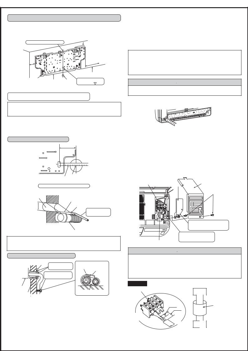
4-4 INDOOR AND OUTDOOR CONNECTING WIRE CONNECTION
You can connect indoor/outdoor lead wire without removing the front panel. 1 Open the front panel.
2 Remove one screw holding the electrical cover, then remove the cover. 3 Remove the VA clamp and the cord clamp.
4Pass the indoor/outdoor unit connecting wire from the back of the indoor unit and process the end of the wire, then connect it to the terminal block.
5 Replace the fi xture and electrical cover securely.
Indoor |
|
|
terminal block |
VA clamp |
ELECTRICAL COVER |
|
|
|
|
|
Fixing screws |
Never fail to hook the left claw on the wire fi xture to secure indoor/ outdoor unit connecting wire A.
Securely push the wire into the terminal block until no
Indoor/outdoor unit connecting wire A part of its core is appeared.
 WARNING
ΟUse the indoor/outdoor unit connecting wire that meets the Standards to connect the indoor and outdoor units and fi x the wire to the terminal block securely so that no external force is conveyed to the connecting section of the terminal block. Incomplete connection or fi xing of the wire could result in a fi re.
ΟAttach the VA clamp securely. If it is attached incorrectly, it could result in a fi re or an electric shock due to dust, water, etc.
MSH type
Loosen terminal screw.
15 mm
35 mm
Terminal block
Lead wire
3N
3N
Indoor terminal block
Indoor/outdoor unit connecting wire A 2-core 1.0 mm2
Outdoor terminal block
<Connection details>
 Loading...