


Mitsubishi MSC-C07TV-E1, MSC-C09TV-E1, MSC-C12TV-E1, MU-C07TV-E1, MU-C09TV-E1 Service Manual
...SPLIT-TYPE,AIR CONDITIONERS
SPLIT-TYPE,HEAT PUMP AIR CONDITIONERS
HFC |
No. OB269 |
|
|
utilized |
|
SERVICE MANUAL |
R407C |
|
Wireless type
Models
MSC-C07TV - E1 (WH) MSC-C09TV - E1 (WH) MSC-C12TV - E1 (WH)
·MU-C07TV
·MU-C09TV
·MU-C12TV
E1-
E1-
E1-
MSC-C07TV - E1 (WH) MSC-C09TV - E1 (WH) MSC-C12TV - E1 (WH)
·MUH-C07TV
·MUH-C09TV
·MUH-C12TV
E1-
E1-
E1-
CONTENTS
MSC-C07TV - E1 MSC-C09TV - E1 MSC-C12TV - E1
1.TECHNICAL CHANGES ················
2.PART NAMES AND FUNCTIONS············
3.SPECIFICATION····················
4.NOISE CRITERIA CURVES ···············
5.OUTLINES AND DIMENSIONS·············
6.WIRING DIAGRAM ··················
7.REFRIGERANT SYSTEM DIAGRAM ··········
8.PERFORMANCE CURVES ···············
9.MICROPROCESSOR CONTROL ············
10.SERVICE FUNCTIONS·················
11.TROUBLESHOOTING ·················
12.DISASSEMBLY INSTRUCTIONS············
13.PARTS LIST······················
1 
 TECHNICAL CHANGES
MSC-C07SV - E1 MSC-C07TV - E1
MSC-C09SV - E1 MSC-C09TV - E1
MSC-C12SV - E1 MSC-C12TV - E1
1.Rated voltage has changed to 230V.
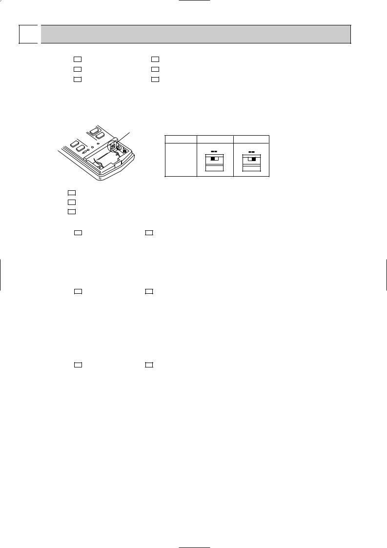
2.Remote controller has changed.
•Slide switch for setting the type has added on the remote controller. Indoor units for MU type and MUH type are common specifications.
Set slide switch on the remote controller according to the type of outdoor unit.
Slide switch
Type |
COOL & HEAT COOL ONLY |
|
The position |
H C |
H C |
|
|
|
of the slide |
|
|
switch |
|
|
MU-C07TV - E1
MU-C09TV - E1
MU-C12TV - E1
New model
MUH-C07SV - E1 MUH-C07TV - E1
1.Rated voltage has changed to 230V.
2.Path of heat exchanger has changed.
3.Refrigerant filling capacity has changed.(0.85kg 0.90kg)
4.Capillary tube has changed.({3.0X{1.6X600 {3.0X{1.6X750, {3.0X{1.4X600 {3.0X{1.4X700)
5.Temperature of defrosting control has changed.
6.Additional refrigerant charge has been changed.(50g/m 25g/m)
MUH-C09SV - E1 MUH-C09TV - E1
1.Rated voltage has changed to 230V.
2.Outdoor heat exchanger has changed.
3.Refrigerant filling capacity has changed.(0.80kg 1.00kg)
4.Capillary tube has changed.
({3.0X{1.6X400 {3.0X{1.8X400, {3.0X{1.4X550 {3.0X{1.4X650, {3.0X{1.4X800 X2 {3.0X{1.4X500 X2)
5.Outdoor fan motor has changed.(RA6V23-EA RA6V33-CA)
6.Temperature of defrosting control has changed.
7.Additional refrigerant charge has been changed.(50g/m 25g/m)
MUH-C12SV - E1 MUH-C12TV - E1
1.Rated voltage has changed to 230V.
2.Path of heat exchanger has changed.
3.Refrigerant filling capacity has changed.(1.20kg 1.25kg)
4.Capillary tube has changed.({3.0X{1.8X250, {3.0X{1.8X400)
5.High pressure protection temperature has changed.
6.Temperature of defrosting control has changed.
7.Additional refrigerant charge has been changed.(50g/m 25g/m)
2
INFORMATION FOR THE AIR CONDITIONER WITH R407C REFRIGERANT
This room air conditioner adopts HFC refrigerant (R407C) which will never destroy the ozone layer. Pay attention to following points.
1Take sufficient care not to allow water and other contaminations to enter the R407C refrigerant during storage and installation, since it is more susceptible to contaminations than HCFC (R22) refrigerant.
2 Clean refrigerant pipings should be used.
3Composition change may occur in R407C since it is a mixed refrigerant. When charging, charge liquid refrigerant to prevent composition change.
4Be especially careful when managing the tools.
If dust, dirt, or water mixes in the refrigerant cycle, it may cause decrease of performance.
|
|
|
New refrigerant |
Previous refrigerant |
|
Refrigerant |
|
R407C |
R22 |
|
Composition (Ratio) |
|
R32: R125: R134a (23%:25%:52%) |
HCFC22 (100%) |
|
Refrigerant handling |
|
Non-azeotropic refrigerant |
Single refrigerant |
|
Chlorine |
|
Not included |
Included |
Refrigerant |
Safety group (ASHRAE) |
|
A1/A1 |
A1 |
Saturated steam density [25:](Kg/K) |
42.5 |
44.4 |
||
|
Molecular weight |
|
86.2 |
86.5 |
|
Boiling point (:) |
|
-43.6 |
-40.8 |
|
Steam pressure [25:](Mpa [Gauge]) |
0.9177 |
0.94 |
|
|
|
|
|
|
|
Combustibility |
|
Non combustible |
Non combustible |
|
ODP w1 |
|
0 |
0.055 |
|
GWP w2 |
|
1530 |
1700 |
|
Refrigerant charge method |
|
From liquid phase in cylinder |
Gas phase |
|
Additional charge on leakage |
|
Impossible |
Possible |
Lubricant |
Kind |
|
Incompatible oil |
Compatible oil |
|
|
|||
|
Color |
|
Non |
Light yellow |
|
Smell |
|
Non |
Non |
w1 :Ozone Destruction Parameter |
: based on CFC11 |
|
||
w2 :Global Warmth Parameter |
: based on CO2 |
|
||
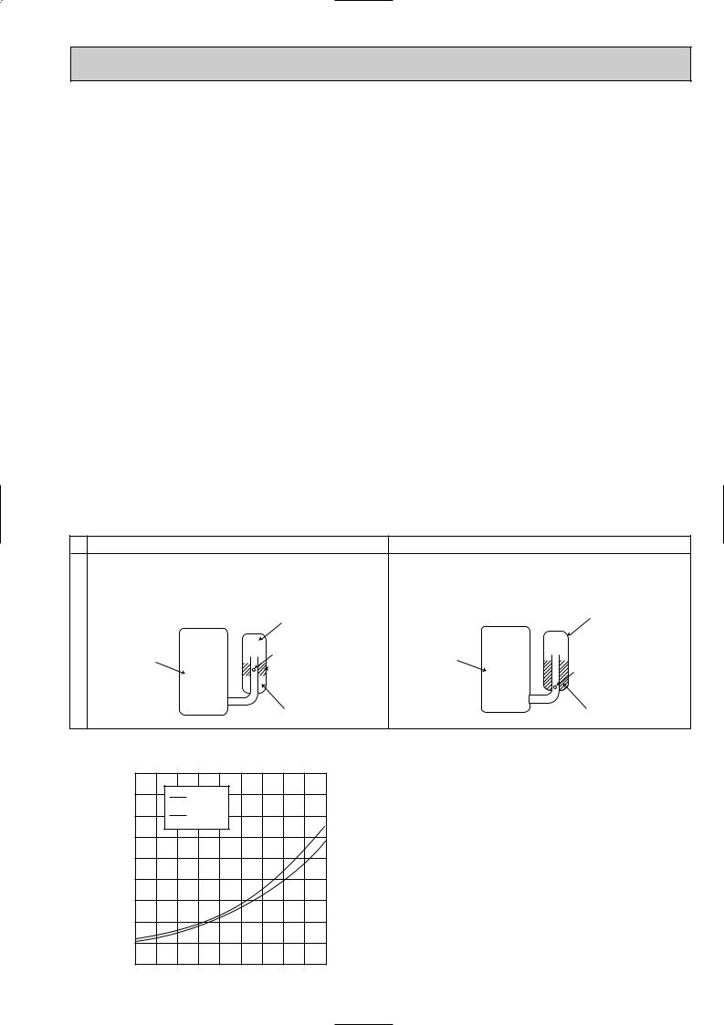
Compressor
|
New Specification |
Previous Specification |
|||||||||||||
The incompatible lubricant easily separates from refrigerant |
Since refrigerant and lubricant are compatible each other, |
||||||||||||||
and makes the layer in the upper inside the suction muffler. |
lubricant returns to the compressor through the lower |
||||||||||||||
The higher position of the returning oil hole enables to return |
position returning oil hole. |
||||||||||||||
the lubricant of the upper layer to the compressor. |
|
|
|
|
|
|
|
||||||||
|
|
|
|
|
|
|
Suction muffler |
|
|
|
|
|
|
Suction muffler |
|
|
|
|
|
|
|
|
|
|
|
|
|
||||
|
|
|
|
|
|
|
Returning oil hole |
|
|
|
|
|
|
|
|
Compressor |
|
|
|
|
|
|
Compressor |
|
|
||||||
|
|
|
|
|
|
|
|
Lubricant |
|
|
|
|
|
|
Returning oil hole |
|
|
|
|
|
|
|
|
|
|
|
|
|
|
||
|
|
|
|
|
|
|
|
||||||||
Refrigerant |
Lubricant and Refrigerant |
Conversion chart of refrigerant temperature and pressure
(MPa[Gauge])
|
4.0 |
|
pressure |
3.5 |
R407C |
2.5 |
||
|
|
|
|
3.0 |
R22 |
liquid |
2.0 |
|
|
|
|
Saturated |
1.5 |
|
1.0 |
|
|
|
|
|
|
0.5 |
|
|
0.0 |
|
-0.5 -30 -20 -10 0 10 20 30 40 50 60 (:)
NOTE : The unit of pressure has been changed to MPa on the international system of units(SI unit system).
The conversion factor is: 1(MPa[Gauge]) =10.2(kgf/f[Gauge])
3
1.Tools dedicated for the air conditioner with R407C refrigerant
The following tools are required for R407C refrigerant. Some R22 tools can be substituted for R407C tools. Do not use tools that are used with R22 refrigerant in order to avoid mixing oils.
R407C tools |
Can R22 tools be used? |
|
Description |
||
Gauge manifold |
No |
A gauge manifold with a sight glass is recommended for charging the |
|||
liquid refregerant. |
|||||
|
|
||||
Charge hose |
No |
Hose material have been changed to improve the pressure |
|||
resistance. |
|||||
|
|
||||
Gas leak detector |
No |
Dedicated for HFC refrigerant. |
|||
|
|
|
|
|
|
Torque wrench |
Yes |
|
|
|
|
|
|
|
|||
|
|
|
|
|
|
Flare tool |
Yes |
|
|
|
|
|
|
|
|||
|
|
|
|
|
|
Vacuum pump |
New |
Provided to prevent the back flow of oil. This adapter enables you to use |
|||
adapter |
existing vacuum pumps. |
||||
|
|||||
Electronic scale for |
New |
Use the electronic control scale for measuring the R407C. |
|||
refrigerant charging |
|||||
|
|
|
|
||
|
|
|
|
|
|
2.Refrigerant piping
Do not use copper pipes which are broken, deformed or discoloured.
In addition, be sure that the inner surfaces of the pipes are clean, free of hazardous sulfur and oxides, or have no dust/ dirt, shaving particles, oil, moisture or any other contamination.
•If there is a large amount of residual oil inside the piping and joints, deterioration of the refrigerant oil will result.
3.Refrigerant oil
Apply the specific refrigeration oil (accessories) to the flare and the union seat surfaces.
4.Air purge
Use the vacuum pump for air purge to protect environments, and to avoid changing the composition of refrigerant.
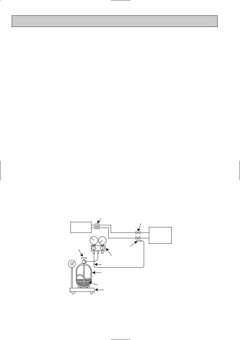
5.Additional charge
For additional charging, charge the refrigerant with liquid phase slowly using a gas cylinder. If the refrigerant is charged with gas phase, the composition of refrigerant will change. In this case, ability of the refrigerating cycle decreases or normal operation can be impossible.
If liquid refrigerant is rapidly charged at once, the compressor may be locked.
NOTE: 1. The R407C is mixed refrigerant which consist of three different kinds of evaporative temperature. As a result, the R407C occurs the change of composition.
2.Additional refrigerant charge has been changed by change of refrigerant.(R22 R407C) R22 : <MU-type> 15g/m R407C : <MU-C07/C09/C12TV> 15g/m
R22 : <MUH-type> 50g/m R407C : <MUH-C07/C09/C12TV> 25g/m
Union
|
|
Stop valve |
Indoor unit |
Liquid pipe |
|
|
|
|
Refrigerant |
Gas pipe |
Outdoor unit |
|
|
|
gas cylinder |
|
|
operating |
Service port |
|
valve |
|
|
|
|
|
|
Gage manifold |
|
|
Charge hose |
|
|
Refrigerant gas cylinder |
|
|
for R407C with siphon |
|
|
Refrigerant (liquid) |
|
|
Electronic scale for |
|
|
refrigerant charging |
|
4
2 
 PART NAMES AND FUNCTIONS
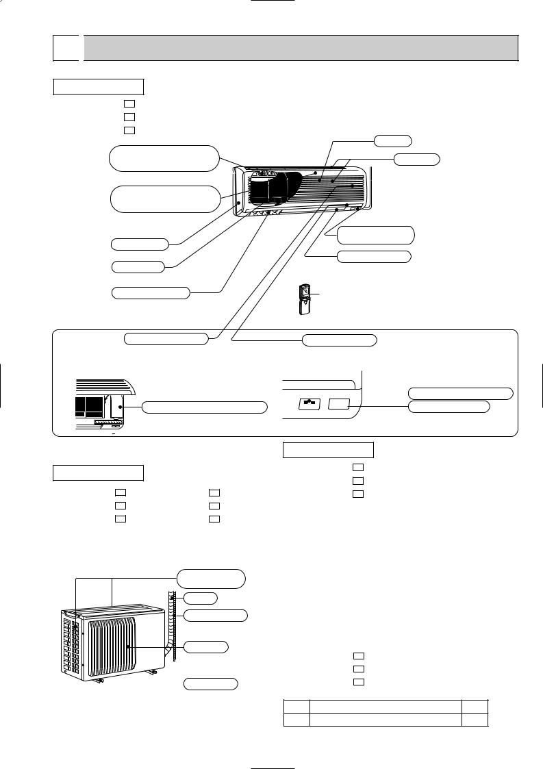
INDOOR UNIT
MSC-C07TV - E1
MSC-C09TV - E1
MSC-C12TV - E1
Deodorizing filter (gray sponge type)
Air cleaning filter (white bellows type)
Front panel
Air filter
Vertical vanes
Operation section
(when the grille is open)
Emergency operation switch
Grille
Air inlet
Remote control receiving section
Horizontal vane
Remote controller
Display section
 Operation indicator lamp
  Receiving section
OUTDOOR UNIT
MU-C07TV - E1 MUH-C07TV - E1 MU-C09TV - E1 MUH-C09TV - E1 MU-C12TV - E1 MUH-C12TV - E1
Air inlet (back and side)
Piping
Drain hose
Air outlet
 Drain outlet
ACCESSORIES
MSC-C07TV - E1
MSC-C09TV - E1
MSC-C12TV - E1
<Indoor unit>
1 |
Installation plate |
1 |
|
|
|
2 |
Installation plate fixing screw 4 x 25 mm |
5 |
|
|
|
3 |
Remote controller mounting hardware |
1 |
|
|
|
4 |
Fixing screw for 3 3.5 x 16 mm (Black) |
2 |
|
|
|
5 |
Battery (AAA) for remote controller |
2 |
|
|
|
6 |
Wireless remote controller |
1 |
|
|
|
7 |
Felt tape (Used for left or left-rear piping) |
1 |
|
|
|
8 |
Deodorizing filter |
1 |
|
|
|
9 |
Air cleaning filter |
1 |
|
|
|
0 |
Refrigeration oil |
1 |
|
|
|
MUH-C07TV - E1
MUH-C09TV - E1
MUH-C12TV - E1
<Outdoor unit : MUH type only>
1 |
Drain socket |
1 |
2 |
Drain cap [33 |
2 |
5
MSC-C07TV - E1
MSC-C09TV - E1
MSC-C12TV - E1
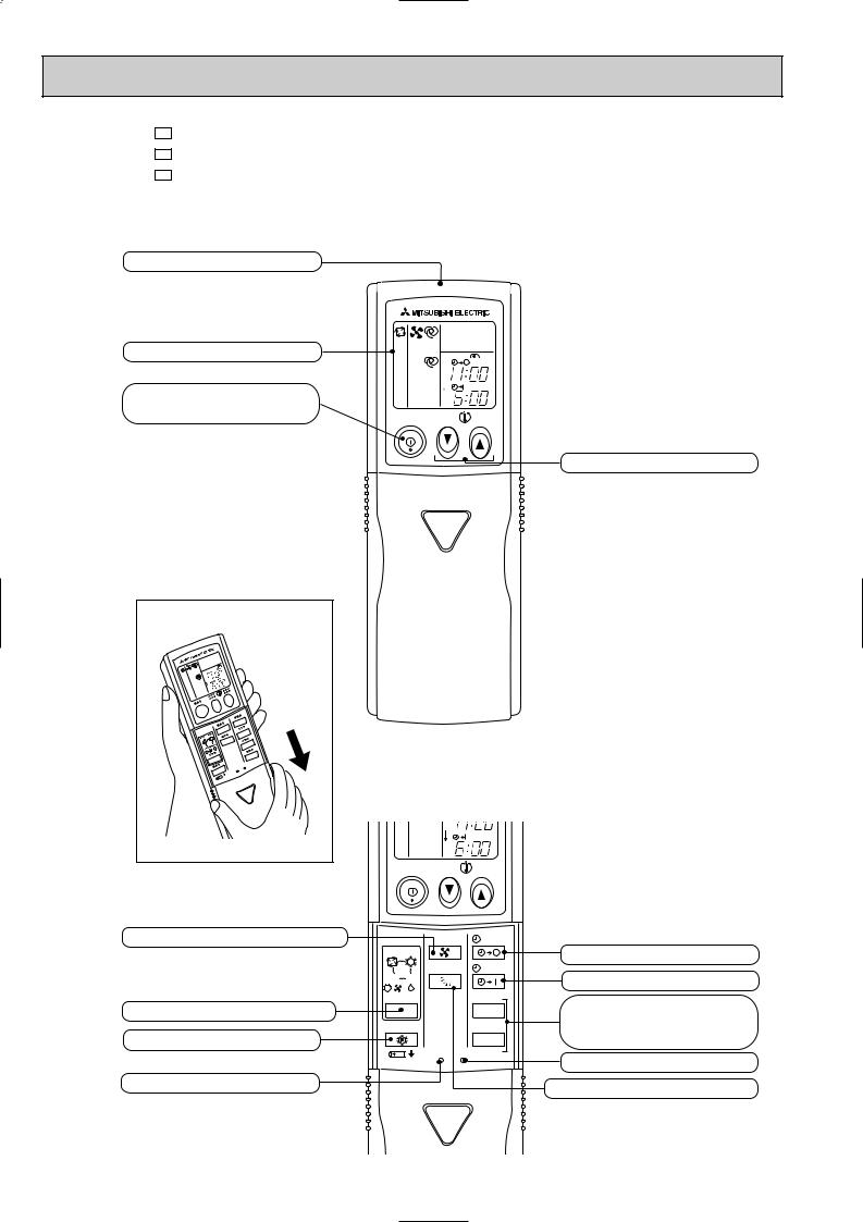
Signal transmitting section
Operation display section
OPERATE /STOP (ON /OFF)button
|
|
PM |
|
|
AM |
ON/OFF |
TOO |
TOO |
|
WARM |
COOL |
TEMPERATURE buttons
Open the front lid. |
FAN SPEED CONTROL button
OPERATION SELECT button ECONO COOL button
RESET button
AM |
ON/OFF |
TOO |
TOO |
|
WARM |
COOL |
|
FAN |
STOP |
I FEEL COOL |
|
|
HEAT |
VANE |
START |
DRY |
|
|
/FAN |
|
|
/ |
|
HR. |
MODE |
||
ECONO COOL |
MIN. |
|
|
RESET CLOCK |
|
OFF-TIMER button
ON-TIMER button
HR. button MIN. button (TIME SET button)
CLOCK SET button
VANE CONTROL button
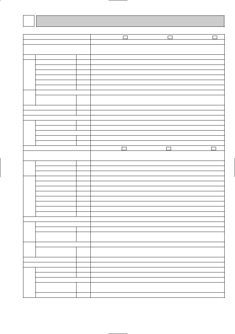
3 SPECIFICATION
Indoor model
Function
Indoor unit power supply
Capacity |
Air flow(High) |
K /h |
|
|
Power outlet |
A |
|
Electrical data |
Running current |
A |
|
Power input |
W |
||
|
|||
|
Power factor |
% |
|
|
Starting current |
A |
|
|
Fan motor current |
A |
|
Fan motor |
Model |
" |
|
Winding |
|||
|
|
||
|
resistance(at20:) |
|
|
|
Dimensions WOHOD |
mm |
|
|
Weight |
kg |
|
|
Air direction |
|
|
Special remarks |
Sound level(High) |
dB |
|
Fan speed(High) |
rpm |
||
|
|||
|
Fan speed regulator |
|
|
|
Thermistor RT11(at25:) |
k" |
|
|
Thermistor RT12(at25:) |
k" |
|
|
Outdoor model |
|
|
Capacity |
Outdoor unit power supply |
|
|
Outdoor air flow |
K /h |
||
|
Capacity |
kW |
|
|
Dehumidification |
R/h |
|
|
Power outlet |
A |
|
Electrical data |
Running current |
A |
|
Power input |
W |
||
|
|||
|
Auxiliary heater |
A(kW) |
|
|
Power factor |
% |
|
|
Starting current |
A |
|
|
Compressor motor current |
A |
|
|
Fan motor current |
A |
|
Coefficient of performance(C.O.P) |
|||
Compressor |
Model |
" |
|
Output |
|||
|
W |
||
|
Winding |
|
|
|
resistance(at20:) |
|
|
Fan motor |
Model |
|
|
Winding |
" |
||
|
|||
|
resistance(at20:) |
||
|
|
||
|
Dimensions WOHOD |
mm |
|
|
Weight |
kg |
|
|
Sound level |
dB |
|
Special remarks |
Fan speed |
rpm |
|
Fan speed regulator |
|
||
Refrigerant filling |
kg |
||
|
capacity(R407C) |
||
|
|
||
|
Refrigerating oil (Model) |
cc |
|
MSC-C07TV - E1 |
MSC-C09TV - E1 |
MSC-C12TV - E1 |
Cooling |
Cooling |
Cooling |
Single phase |
Single phase |
Single phase |
230V,50Hz |
230V,50Hz |
230V,50Hz |
474 |
474 |
588 |
10 |
10 |
10 |
0.17 |
0.17 |
0.19 |
35 |
35 |
40 |
90 |
90 |
92 |
— |
— |
— |
0.17 |
0.17 |
0.19 |
RC4V19-BA |
RC4V19-BA |
RC4V19-BA |
WHT-BLK 292 |
WHT-BLK 292 |
WHT-BLK 292 |
BLK-RED 325 |
BLK-RED 325 |
BLK-RED 325 |
850O278O191 |
850O278O191 |
850O278O191 |
9 |
9 |
10 |
5 |
5 |
5 |
36 |
36 |
39 |
950 |
950 |
1020 |
3 |
3 |
3 |
10 |
10 |
10 |
10 |
10 |
10 |
MU-C07TV - E1 |
MU-C09TV - E1 |
MU-C12TV - E1 |
Single phase |
Single phase |
Single phase |
230V,50Hz |
230V,50Hz |
230V,50Hz |
2.25 |
2.5 |
3.55 |
0.8 |
1.0 |
1.6 |
1686 |
1686 |
1914 |
10 |
10 |
10 |
3.03 |
3.53 |
6.01 |
695 |
795 |
1330 |
— |
— |
— |
99 |
98 |
96 |
18 |
19 |
34 |
2.75 |
3.25 |
5.64 |
0.29 |
0.29 |
0.37 |
3.08 |
3.01 |
2.59 |
RE-130VGSHT |
RE-145VGSHT |
RE-231VHSHT |
650 |
700 |
1100 |
C-R 4.18 |
C-R 4.03 |
C-R 2.25 |
C-S 5.76 |
C-S 5.71 |
C-S 4.07 |
RA6V23-EB |
RA6V23-EB |
RA6V33-CB |
WHT-BLK 258 |
WHT-BLK 258 |
WHT-BLK 176 |
BLK-RED 385 |
BLK-RED 385 |
BLK-RED 413 |
780o540o255 |
780o540o255 |
780o540o255 |
32 |
32 |
34 |
45 |
45 |
49 |
645 |
645 |
725 |
1 |
1 |
1 |
0.77 |
0.88 |
0.90 |
350 (NEO22 ) |
350 (NEO22 ) |
620 (NEO22) |
NOTE:Test conditions are based on JIS C 9612. Cooling : Indoor DB27°C / WB19°C
Outdoor DB35°C / WB24°C
7
|
Indoor model |
|
|
MSC-C07TV - E1 |
|
MSC-C09TV - E1 |
||||||||
|
Function |
|
|
Cooling |
|
Heating |
|
Cooling |
|
Heating |
||||
|
Indoor unit power supply |
|
|
Single phase |
|
Single phase |
||||||||
|
|
|
230V,50Hz |
|
230V,50Hz |
|||||||||
|
|
|
|
|
||||||||||
Capacity |
Air flow(High) |
K /h |
|
474 |
|
|
|
504 |
|
474 |
|
|
|
504 |
|
Power outlet |
A |
|
|
|
10 |
|
|
|
|
|
10 |
|
|
Electrical data |
Running current |
A |
|
|
0.17 |
|
|
|
0.17 |
|
||||
Power factor |
% |
|
|
|
90 |
|
|
|
|
|
90 |
|
|
|
|
Power input |
W |
|
|
|
35 |
|
|
|
|
|
35 |
|
|
|
Starting current |
A |
|
|
|
— |
|
|
|
|
|
— |
|
|
|
Fan motor current |
A |
|
|
0.17 |
|
|
|
0.17 |
|
||||
Fan motor |
Model |
" |
|
RC4V19-BA |
|
RC4V19-BA |
||||||||
Winding |
|
WHT-BLK 292 |
|
WHT-BLK 292 |
||||||||||
|
|
|
|
|||||||||||
|
resistance(at20:) |
|
|
BLK-RED 325 |
|
BLK-RED 325 |
||||||||
|
Dimensions WOHOD |
mm |
|
850 |
O |
278 |
O |
191 |
|
850 |
O |
278 |
O |
191 |
|
|
|
|
|
|
|
|
|||||||
|
Weight |
kg |
|
|
|
9 |
|
|
|
|
|
9 |
|
|
|
Air direction |
|
|
|
|
5 |
|
|
|
|
|
5 |
|
|
|
Sound level(High) |
dB |
|
36 |
|
|
|
35 |
|
36 |
|
|
|
35 |
Special remarks |
Fan speed(High) |
rpm |
|
950 |
|
|
|
1000 |
|
950 |
|
|
|
1000 |
Fan speed regulator |
|
|
|
|
3 |
|
|
|
|
|
3 |
|
|
|
|
|
|
|
|
|
|
|
|
|
|
|
|||
|
Thermistor RT11(at25:) |
k" |
|
|
|
10 |
|
|
|
|
|
10 |
|
|
|
Thermistor RT12(at25:) |
k" |
|
|
|
10 |
|
|
|
|
|
10 |
|
|
|
Outdoor model |
|
|
MUH-C07TV - E1 |
|
MUH-C09TV - E1 |
||||||||
|
Outdoor unit power supply |
|
|
Single phase |
|
Single phase |
||||||||
|
|
|
230V,50Hz |
|
230V,50Hz |
|||||||||
Capacity |
Outdoor air flow |
K /h |
|
|
||||||||||
|
2.2 |
1686 |
2.5 |
|
2.55 |
1914 |
3.2 |
|||||||
|
Capacity |
kW |
|
|
|
|
|
|
|
|
||||
|
Dehumidification |
R/h |
|
0.7 |
|
|
|
— |
|
1.0 |
|
|
|
— |
|
Power outlet |
A |
|
|
|
10 |
|
|
|
|
|
10 |
|
|
|
Running current |
A |
|
3.23 |
|
|
|
2.93 |
|
3.83 |
|
|
|
4.13 |
|
Power input |
W |
|
735 |
|
|
|
675 |
|
875 |
|
|
|
925 |
Electrical data |
Auxiliary heater |
A(kW) |
|
|
|
— |
|
|
|
|
|
— |
|
|
Power factor |
% |
|
|
|
99 |
|
|
|
99 |
|
|
|
97 |
|
|
|
|
|
|
|
|
|
|
|
|||||
|
Starting current |
A |
|
|
|
18 |
|
|
|
|
|
22 |
|
|
|
Compressor motor current |
A |
|
2.95 |
|
|
|
2.65 |
|
3.46 |
|
|
|
3.76 |
|
Fan motor current |
A |
|
|
0.29 |
|
|
|
0.37 |
|
||||
Coefficient of performance(C.O.P) |
|
2.86 |
|
|
|
3.52 |
|
2.80 |
|
|
|
3.33 |
||
Compressor |
Model |
|
|
RE-135VGSHT |
|
RE-174VGSHT |
||||||||
Output |
W |
|
|
|
650 |
|
|
|
|
|
800 |
|
|
|
|
|
|
|
|
|
|
|
|
|
|
||||
|
Winding |
" |
|
C-R 4.18 |
|
C-R 3.30 |
||||||||
|
resistance(at20:) |
|
C-S 5.76 |
|
C-S 5.80 |
|||||||||
|
|
|
|
|||||||||||
Fan motor |
Model |
" |
|
RA6V23-EA |
|
RA6V33-CA |
||||||||
Winding |
|
WHT-BLK 258 |
|
WHT-BLK 176 |
||||||||||
|
|
|
|
|||||||||||
|
resistance(at20:) |
|
|
BLK-RED 385 |
|
BLK-RED 413 |
||||||||
|
Dimensions WOHOD |
mm |
|
|
o |
|
o |
255 |
|
780 |
o |
540 |
o |
255 |
|
|
|
780 540 |
|
|
|
|
|||||||
|
Weight |
kg |
|
|
|
34 |
|
|
|
|
|
36 |
|
|
|
Sound level |
dB |
|
|
|
47 |
|
|
|
|
|
49 |
|
|
|
Fan speed |
rpm |
|
|
|
645 |
|
|
|
|
|
720 |
|
|
Special remarks |
Fan speed regulator |
kg |
|
|
|
1 |
|
|
|
|
|
1 |
|
|
Refrigerant filling |
|
|
0.90 |
|
|
|
1.00 |
|
||||||
|
|
|
|
|
|
|
|
|
|
|
|
|
|
|
|
capacity(R407C) |
|
|
|
|
|
|
|
|
|
|
|
|
|
|
Refrigerating oil (Model) |
cc |
|
350 |
(NEO22) |
|
350 |
(NEO22) |
||||||
|
Thermistor RT61(at0:) |
k" |
|
|
33.18 |
|
|
|
33.18 |
|
||||
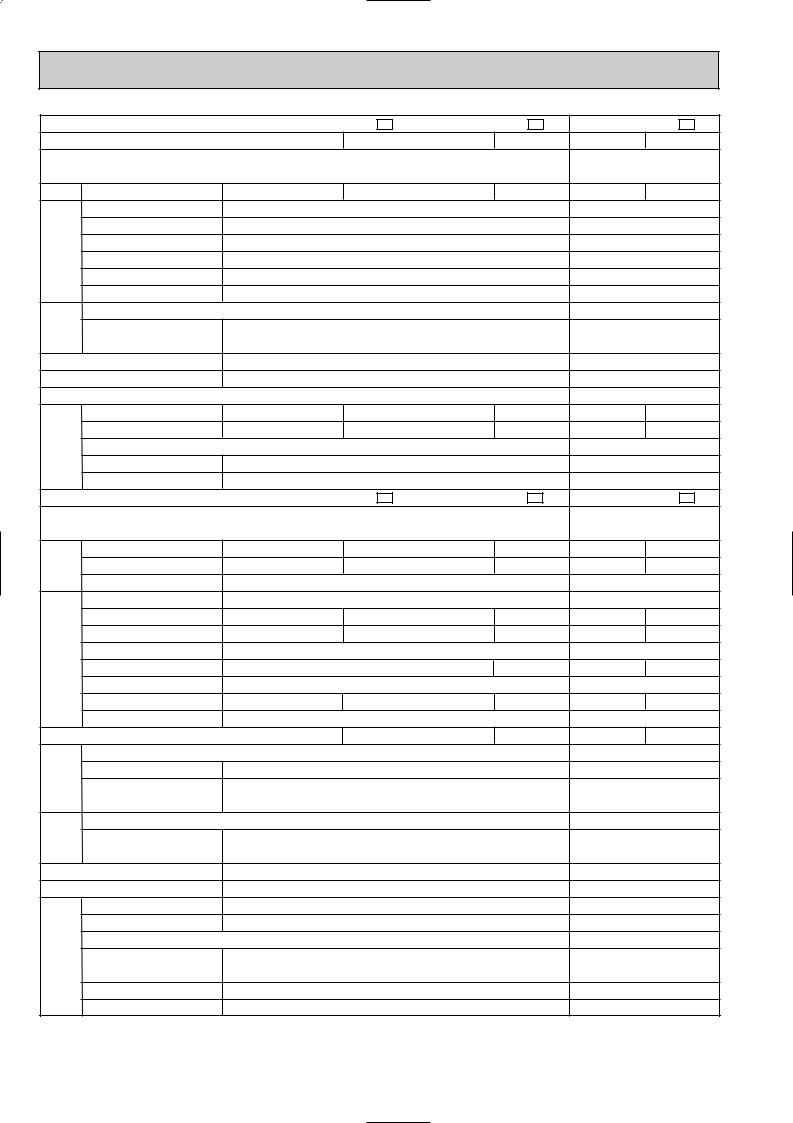
NOTE:Test conditions are based on JIS C 9612. |
|
|
|
|
|
|
|
|
|
|
||||
|
Cooling : Indoor DB27°C / WB19°C |
Heating : Indoor DB20°C |
|
|
|
|
|
|||||||
|
Outdoor DB35°C / WB24°C |
|
|
|
|
Outdoor DB 7°C / WB 6°C |
|
|
||||||
MSC-C12TV - E1
Cooling Heating
Single phase 230V,50Hz
588 576
10
0.19
40
92
—
0.19
RC4V19-BA
WHT-BLK 292
BLK-RED 325
850O278O191
10
5
39 |
39 |
1020 |
1000 |
3
10
10
MUH-C12TV - E1
Single phase 230V,50Hz
3.454.2
1.5 —
1914
10
5.716.01
1240 1310
—
94 95
34
5.345.64
0.37
2.70 3.11
RE-231VHSHT
1100
C-R 2.25
C-S 4.07
RA6V33-CA
WHT-BLK 176
BLK-RED 413
780o540o255
39
49
720
1
1.25
620 (NEO22)
33.18
8

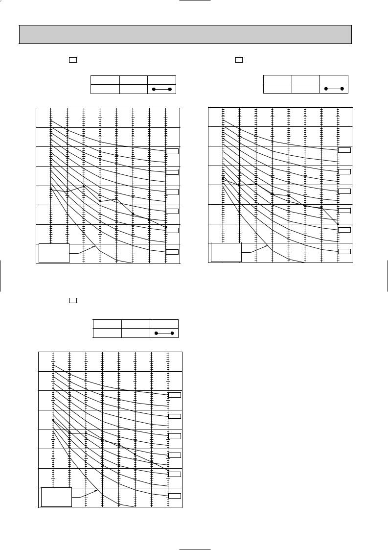
4 NOISE CRITERIA CURVES
MSC-C07TV - E1 |
|
|
|
|
|
|
|
MSC-C12TV - E1 |
|
|
|
|
|
||||||
MSC-C09TV - E1 |
|
|
|
|
|
|
|
|
|
|
|
|
|
|
|
|
|||
|
|
|
|
|
NOTCH |
SPL(dB(A)) |
LINE |
|
|
|
|
|
NOTCH |
SPL(dB(A)) |
LINE |
||||
|
|
|
|
|
High |
|
36 |
|
|
|
|
|
|
|
High |
|
39 |
|
|
|
Test conditions, |
|
|
|
|
|
|
|
|
Test conditions, |
|
|
|
|
|
|
|
||
|
|
Cooling : Dry-bulb temperature 27: Wet-bulb temperature 19: |
|
|
Cooling : Dry-bulb temperature 27: Wet-bulb temperature 19: |
||||||||||||||
|
90 |
Heating : Dry-bulb temperature 20: |
|
|
|
|
90 |
Heating : Dry-bulb temperature 20: |
|
|
|
||||||||
BAR |
|
|
|
|
|
|
|
|
BAR |
|
|
|
|
|
|
|
|
||
|
|
|
|
|
|
|
|
|
|
|
|
|
|
|
|
|
|
||
MICRO |
80 |
|
|
|
|
|
|
|
|
MICRO |
80 |
|
|
|
|
|
|
|
|
|
|
|
|
|
|
|
|
|
|
|
|
|
|
|
|
|
|
||
0.0002 |
70 |
|
|
|
|
|
|
|
NC-70 |
0.0002 |
70 |
|
|
|
|
|
|
|
NC-70 |
|
|
|
|
|
|
|
|
|
|
|
|
|
|
|
|
||||
dB re |
60 |
|
|
|
|
|
|
|
|
dB re |
60 |
|
|
|
|
|
|
|
|
LEVEL, |
|
|
|
|
|
|
|
|
LEVEL, |
|
|
|
|
|
|
|
|
||
|
|
|
|
|
|
|
|
NC-60 |
|
|
|
|
|
|
|
|
NC-60 |
||
50 |
|
|
|
|
|
|
|
|
|
|
|
|
|
|
|
|
|
||
PRESSURE |
|
|
|
|
|
|
|
|
PRESSURE |
50 |
|
|
|
|
|
|
|
|
|
|
|
|
|
|
|
|
|
NC-50 |
|
|
|
|
|
|
|
|
NC-50 |
||
40 |
|
|
|
|
|
|
|
|
40 |
|
|
|
|
|
|
|
|
||
|
|
|
|
|
|
|
|
NC-40 |
|
|
|
|
|
|
|
|
NC-40 |
||
SOUND |
|
|
|
|
|
|
|
|
SOUND |
|
|
|
|
|
|
|
|
||
30 |
|
|
|
|
|
|
|
|
30 |
|
|
|
|
|
|
|
|
||
BAND |
|
|
|
|
|
|
|
|
NC-30 |
BAND |
|
|
|
|
|
|
|
|
NC-30 |
20 |
|
|
|
|
|
|
|
|
20 |
|
|
|
|
|
|
|
|
||
OCTAVE |
APPROXIMATE |
|
|
|
|
|
|
OCTAVE |
APPROXIMATE |
|
|
|
|
|
|
||||
|
|
|
|
|
|
|
|
|
|
|
|
|
|
||||||
|
THRESHOLD OF |
|
|
|
|
|
NC-20 |
|
THRESHOLD OF |
|
|
|
|
|
NC-20 |
||||
|
HEARING FOR |
|
|
|
|
|
|
HEARING FOR |
|
|
|
|
|
||||||
|
|
|
|
|
|
|
|
|
|
|
|
|
|
||||||
|
CONTINUOUS |
|
|
|
|
|
|
|
CONTINUOUS |
|
|
|
|
|
|
||||
10 |
NOISE |
|
|
|
|
|
|
|
10 |
NOISE |
|
|
|
|
|
|
|
||
|
63 |
125 |
250 |
500 |
1000 |
2000 |
4000 |
8000 |
|
63 |
125 |
250 |
500 |
1000 |
2000 |
4000 |
8000 |
||
|
|
|
|
||||||||||||||||
BAND CENTER FREQUENCIES, Hz BAND CENTER FREQUENCIES, Hz
MU-C07TV - E1 |
|
|
|
|
|
MU-C12TV - E1 |
|
|
|
|
|
||
MU-C09TV - E1 |
|
|
|
|
|
|
|
|
|
|
|
|
|
|
|
|
|
|
|
|
|
|
|
|
|
||
|
NOTCH |
SPL(dB(A)) |
LINE |
|
|
NOTCH |
SPL(dB(A)) |
LINE |
|
||||
|
|
|
|
|
|
|
|
|
|
|
|
|
|
|
High |
45 |
|
|
|
|
|
High |
49 |
|
|
|
|
|
|
|
|
||||||||||
|
|
|
|
|
|
|
|
|
|
|
|
|
|
Test conditions, |
|
|
|
|
|
Test conditions, |
|
|
|
|
|
||
Cooling : Dry-bulb temperature 35: Wet-bulb temperature 24: |
Cooling : Dry-bulb temperature 35: Wet-bulb temperature 24: |
||||||||||||
BAR |
90 |
|
|
|
|
|
|
|
|
BAR |
90 |
|
|
|
|
|
|
|
|
|
|
|
|
|
|
|
|
|
|
|
|
|
|
|
|
|
|
||
MICRO |
80 |
|
|
|
|
|
|
|
|
MICRO |
80 |
|
|
|
|
|
|
|
|
|
|
|
|
|
|
|
|
|
|
|
|
|
|
|
|
|
|
||
0.0002 |
70 |
|
|
|
|
|
|
|
NC-70 |
0.0002 |
70 |
|
|
|
|
|
|
|
NC-70 |
|
|
|
|
|
|
|
|
|
|
|
|
|
|
|
|
||||
dB re |
60 |
|
|
|
|
|
|
|
|
dB re |
60 |
|
|
|
|
|
|
|
|
LEVEL, |
|
|
|
|
|
|
|
|
LEVEL, |
|
|
|
|
|
|
|
|
||
|
|
|
|
|
|
|
|
NC-60 |
|
|
|
|
|
|
|
|
NC-60 |
||
50 |
|
|
|
|
|
|
|
|
50 |
|
|
|
|
|
|
|
|
||
PRESSURE |
|
|
|
|
|
|
|
|
PRESSURE |
|
|
|
|
|
|
|
|
||
|
|
|
|
|
|
|
|
NC-50 |
|
|
|
|
|
|
|
|
NC-50 |
||
40 |
|
|
|
|
|
|
|
|
40 |
|
|
|
|
|
|
|
|
||
|
|
|
|
|
|
|
|
NC-40 |
|
|
|
|
|
|
|
|
NC-40 |
||
SOUND |
|
|
|
|
|
|
|
|
SOUND |
|
|
|
|
|
|
|
|
||
30 |
|
|
|
|
|
|
|
|
30 |
|
|
|
|
|
|
|
|
||
BAND |
|
|
|
|
|
|
|
|
NC-30 |
BAND |
|
|
|
|
|
|
|
|
NC-30 |
20 |
|
|
|
|
|
|
|
|
20 |
|
|
|
|
|
|
|
|
||
OCTAVE |
APPROXIMATE |
|
|
|
|
|
|
OCTAVE |
APPROXIMATE |
|
|
|
|
|
|
||||
|
|
|
|
|
|
|
|
|
|
|
|
|
|
||||||
|
THRESHOLD OF |
|
|
|
|
|
NC-20 |
|
THRESHOLD OF |
|
|
|
|
|
NC-20 |
||||
|
HEARING FOR |
|
|
|
|
|
|
HEARING FOR |
|
|
|
|
|
||||||
|
|
|
|
|
|
|
|
|
|
|
|
|
|
||||||
|
CONTINUOUS |
|
|
|
|
|
|
|
CONTINUOUS |
|
|
|
|
|
|
||||
10 |
NOISE |
|
|
|
|
|
|
|
10 |
NOISE |
|
|
|
|
|
|
|
||
|
|
|
|
|
|
|
|
|
|
|
|
|
|
|
|
||||
|
63 |
125 |
250 |
500 |
1000 |
2000 |
4000 |
8000 |
|
63 |
125 |
250 |
500 |
1000 |
2000 |
4000 |
8000 |
||
|
|
|
|
||||||||||||||||
BAND CENTER FREQUENCIES, Hz |
BAND CENTER FREQUENCIES, Hz |
9
MUH-C07TV - E1 |
|
|
|
|
|
|
MUH-C12TV - E1 |
|
|
|
|
|
|
||||||
|
|
|
|
|
NOTCH |
SPL(dB(A)) |
LINE |
|
|
|
|
|
NOTCH |
SPL(dB(A)) |
LINE |
||||
|
|
|
|
|
High |
|
47 |
|
|
|
|
|
|
|
High |
|
49 |
|
|
|
Test conditions, |
|
|
|
|
|
|
|
|
Test conditions, |
|
|
|
|
|
|
|
||
|
90 |
Heating : Dry-bulb temperature 7: Wet-bulb temperature 6: |
|
90 |
Heating : Dry-bulb temperature 7: Wet-bulb temperature 6: |
||||||||||||||
BAR |
|
|
|
|
|
|
|
|
BAR |
|
|
|
|
|
|
|
|
||
|
|
|
|
|
|
|
|
|
|
|
|
|
|
|
|
|
|
||
MICRO |
80 |
|
|
|
|
|
|
|
|
MICRO |
80 |
|
|
|
|
|
|
|
|
|
|
|
|
|
|
|
|
|
|
|
|
|
|
|
|
|
|
||
0.0002 |
70 |
|
|
|
|
|
|
|
NC-70 |
0.0002 |
70 |
|
|
|
|
|
|
|
NC-70 |
|
|
|
|
|
|
|
|
|
|
|
|
|
|
|
|
||||
dB re |
60 |
|
|
|
|
|
|
|
|
dB re |
60 |
|
|
|
|
|
|
|
|
LEVEL, |
|
|
|
|
|
|
|
|
LEVEL, |
|
|
|
|
|
|
|
|
||
|
|
|
|
|
|
|
|
NC-60 |
|
|
|
|
|
|
|
|
NC-60 |
||
|
|
|
|
|
|
|
|
|
50 |
|
|
|
|
|
|
|
|
||
PRESSURE |
50 |
|
|
|
|
|
|
|
|
PRESSURE |
|
|
|
|
|
|
|
|
|
|
|
|
|
|
|
|
|
NC-50 |
|
|
|
|
|
|
|
|
NC-50 |
||
40 |
|
|
|
|
|
|
|
|
40 |
|
|
|
|
|
|
|
|
||
|
|
|
|
|
|
|
|
NC-40 |
|
|
|
|
|
|
|
|
NC-40 |
||
SOUND |
|
|
|
|
|
|
|
|
SOUND |
|
|
|
|
|
|
|
|
||
30 |
|
|
|
|
|
|
|
|
30 |
|
|
|
|
|
|
|
|
||
BAND |
|
|
|
|
|
|
|
|
NC-30 |
BAND |
|
|
|
|
|
|
|
|
NC-30 |
20 |
|
|
|
|
|
|
|
|
20 |
|
|
|
|
|
|
|
|
||
OCTAVE |
APPROXIMATE |
|
|
|
|
|
|
OCTAVE |
APPROXIMATE |
|
|
|
|
|
|
||||
|
|
|
|
|
|
|
|
|
|
|
|
|
|
||||||
|
THRESHOLD OF |
|
|
|
|
|
NC-20 |
|
THRESHOLD OF |
|
|
|
|
|
NC-20 |
||||
|
HEARING FOR |
|
|
|
|
|
|
HEARING FOR |
|
|
|
|
|
||||||
|
|
|
|
|
|
|
|
|
|
|
|
|
|
||||||
|
CONTINUOUS |
|
|
|
|
|
|
|
CONTINUOUS |
|
|
|
|
|
|
||||
10 |
NOISE |
|
|
|
|
|
|
|
10 |
NOISE |
|
|
|
|
|
|
|
||
|
63 |
125 |
250 |
500 |
1000 |
2000 |
4000 |
8000 |
|
63 |
125 |
250 |
500 |
1000 |
2000 |
4000 |
8000 |
||
|
|
|
|
||||||||||||||||
BAND CENTER FREQUENCIES, Hz |
BAND CENTER FREQUENCIES, Hz |
MUH-C09TV - E1
NOTCH SPL(dB(A)) LINE
High 49
Test conditions,
Heating : Dry-bulb temperature 7: Wet-bulb temperature 6:
BAR |
90 |
|
|
|
|
|
|
|
|
|
|
|
|
|
|
|
|
|
|
MICRO |
80 |
|
|
|
|
|
|
|
|
|
|
|
|
|
|
|
|
|
|
0.0002 |
70 |
|
|
|
|
|
|
|
NC-70 |
|
|
|
|
|
|
|
|
||
dB re |
60 |
|
|
|
|
|
|
|
|
LEVEL, |
|
|
|
|
|
|
|
|
|
|
|
|
|
|
|
|
|
NC-60 |
|
50 |
|
|
|
|
|
|
|
|
|
PRESSURE |
|
|
|
|
|
|
|
|
|
|
|
|
|
|
|
|
|
NC-50 |
|
40 |
|
|
|
|
|
|
|
|
|
|
|
|
|
|
|
|
|
NC-40 |
|
SOUND |
|
|
|
|
|
|
|
|
|
30 |
|
|
|
|
|
|
|
|
|
BAND |
|
|
|
|
|
|
|
|
NC-30 |
20 |
|
|
|
|
|
|
|
|
|
OCTAVE |
APPROXIMATE |
|
|
|
|
|
|
||
|
|
|
|
|
|
|
|||
|
THRESHOLD OF |
|
|
|
|
|
NC-20 |
||
|
HEARING FOR |
|
|
|
|
|
|||
|
|
|
|
|
|
|
|||
|
CONTINUOUS |
|
|
|
|
|
|
||
10 |
NOISE |
|
|
|
|
|
|
|
|
|
|
|
|
|
|
|
|
||
|
63 |
125 |
250 |
500 |
1000 |
2000 |
4000 |
8000 |
|
|
|
||||||||
BAND CENTER FREQUENCIES, Hz
10
5 
 OUTLINES AND DIMENSIONS
MSC-C07TV - E1 |
|
|
82 |
|
MSC-C09TV - E1 |
|
|
|
|
INDOOR UNIT |
|
Installation plate |
|
|
|
|
|
|
|
|
|
Indoor unit |
|
|
|
818 |
|
|
|
|
|
|
41 |
|
|
|
|
81.5 |
326 |
|
850 |
|
|
|
278 |
|
|
ormore |
|
|
|
|
Air in |
|
|
|
|
7 |
|
56 |
629 |
165 |
100 |
|
|
|
|||
58 |
19 |
|
Air out |
|
|
|
|
Power supply cord |
|
162 |
|
|
Lead to right 1.0m |
|
|
|
Lead to left 0.3m |
|
|
|
|
|
|
|
Wireless remote controller
Unit: mm
169 |
|
4.5 |
|
|
|
|
231.5 |
271 |
2.5 |
42 |
|
326 116.5
Wall hole [65
5
189Installation plate
{Liquid line [6.35-0.5m Gas line [9.52-0.43m Insulation [37 O.D
[21 I.D
67Drain hose [16 (Connected part O.D)
78 |
Insulation [28 |
MSC-C12TV - E1
INDOOR UNIT
818
850
278
56 |
629 |
58 |
19 |
162 |
|
Wireless remote controller
82
Installation plate
Indoor unit
41
81.5326
Air in |
more |
|
7 or |
165 |
100 |
Air out
Power supply cord
Lead to right 1.0m
Lead to left 0.3m
11
169 |
|
4.5 |
|
|
|
|
231.5 |
271 |
2.5 |
42 |
|
326 116.5
Wall hole [65
5
189Installation plate
{Liquid line [6.35-0.5m Gas line [9.52-0.43m Insulation [37 O.D
[21 I.D
67Drain hose [16 (Connected part O.D)
78 |
Insulation [28 |
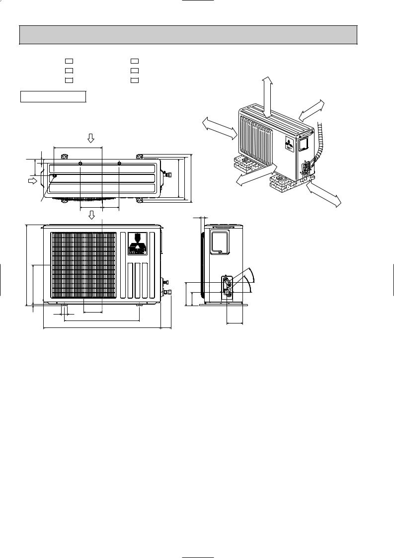
MU-C07TV - E1 MUH-C07TV - E1 MU-C09TV - E1 MUH-C09TV - E1 MU-C12TV - E1 MUH-C12TV - E1
OUTDOOR UNIT
|
Air in |
|
320 |
32 |
|
109 |
|
Air in |
|
Drainage |
147 110 |
3holes [33 |
Airout |
540
260 |
|
|
10 |
40 |
122 |
|
500
780
Unit: mm
REQUIRED SPACE |
moreor |
|
|
|
|
|
|
||
|
|
100mm |
or |
more |
|
|
|
|
|
Outdoor |
|
100mm |
|
|
100mm |
unit |
|
|
|
or |
|
|
|
|
|
|
|
|
|
|
more |
|
|
|
255 285 320 |
400mm |
more |
|
||
|
|
or |
|
|
|
|
|
|
350mm |
or |
|
|
|
|
|
||
|
|
|
|
more |
|
|
25 |
|
|
|
|
|
Service panel |
|
|||
|
|
Liquid refrigerant |
|
||
|
|
|
pipe joint |
|
|
|
|
Refrigerant pipe |
|
||
|
- |
(flared) [6.35 |
|
||
|
35 |
|
|
||
|
- |
|
|
|
|
155 90 |
43 |
|
|
|
|
|
Gas refrigerant |
|
|||
|
|
|
|||
|
|
|
pipe joint |
|
|
74 |
104 |
Refrigerant pipe |
|
||
(flared) [9.52 (MU-C07/C09TV) |
|||||
|
|||||
(MUH-C07/C09TV) [12.7 (MU-C12TV)
(MUH-C12TV)
12
6 
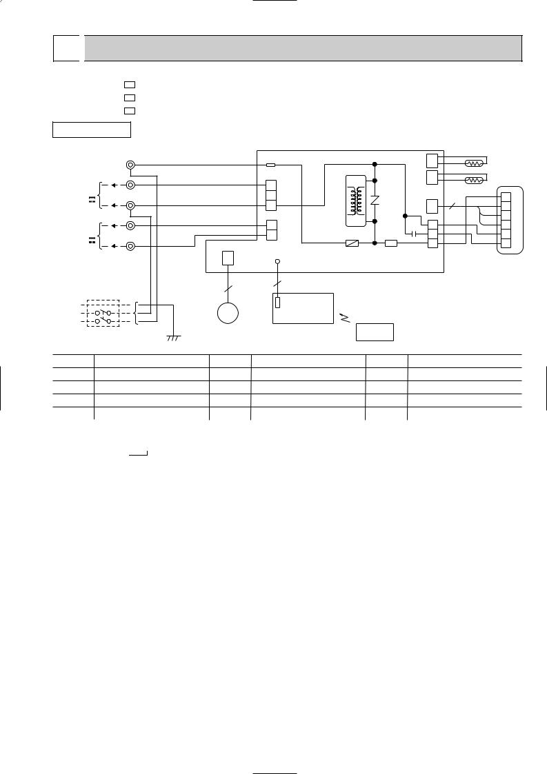
 WIRING DIAGRAM
MSC-C07TV - E1 |
|
MSC-C09TV - E1 |
|
MSC-C12TV - E1 |
MODELS WIRING DIAGRAM |
INDOOR UNIT
TO OUTDOOR |
TB |
|
|
|
|
|
|
|
|
UNIT |
BRN |
|
|
TAB12 |
|
|
CN |
|
|
CONNECTING |
L |
|
|
|
|
|
|||
BRN |
|
|
|
|
|
|
112 |
|
|
FOR |
|
|
|
CN201 |
HIC1 |
CN |
|
||
MUH TYPE |
3 |
RED |
|
|
|
|
111 |
|
|
|
|
3 |
|
|
|
||||
|
|
|
|
|
|
|
|
|
|
12V |
N |
BLU |
|
|
2 |
|
NR11 |
CN |
3 |
|
|
1 |
|
||||||
FOR |
BLU |
|
|
|
|
|
121 |
|
|
|
|
|
CN202 |
|
|
|
|||
|
|
|
|
|
|
|
|||
MU TYPE |
2 |
WHT |
|
|
TRANS |
1 |
|
||
|
|
2 |
|
||||||
|
|
|
|
|
|
C11 |
|
||
12V |
1 |
BLK |
|
|
1 |
F11 |
SR141 |
2 |
|
|
|
|
|
|
3 |
|
|||
POWER |
|
|
CN |
|
LD101T |
|
CN211 |
|
|
|
|
151 |
|
ELECTRONIC CONTROL P.C. BOARD |
|
|
|||
SUPPLY |
|
|
|
|
|
|
|||
CORD |
|
|
|
|
|
|
|
|
|
~/N 230V |
|
|
|
5 |
5 |
|
|
|
|
50Hz |
|
|
|
POWER MONITOR, |
|
|
|
|
|
PE |
|
|
|
|
|
|
|
|
|
|
GRN/YLW |
MV |
|
RECEIVER |
|
|
|
|
|
|
|
|
|
|
|
|
|||
|
|
|
P.C.BOARD |
|
|
|
|
||
|
|
|
|
|
|
|
|
||
CIRCUIT BREAKER |
|
|
|
|
REMOTE |
|
|
||
|
|
|
|
CONTROLLER |
|
|
|||
|
|
|
|
|
|
|
|||
|
|
|
|
|
|
|
|
|
|
RT12
RT11
BLK |
1 |
|
GRY |
||
2 |
||
YLW |
||
43 MF |
||
BRN |
||
WHT |
5 |
|
RED |
6 |
|
|
SYMBOL |
NAME |
SYMBOL |
NAME |
SYMBOL |
NAME |
C11 |
INDOOR FAN CAPACITOR |
MV |
VANE MOTOR |
SR141 |
SOLID STATE RELAY |
F11 |
FUSE(3.15A) |
NR11 |
VARISTOR |
TB |
TERMINAL BLOCK |
HIC1 |
DC/DC CONVERTER |
RT11 |
ROOM TEMPERATURE THERMISTOR |
|
|
MF |
INDOOR FAN MOTOR(INNER FUSE) |
RT12 |
INDOOR COIL THERMISTOR |
|
|
NOTE:1. About the outdoor side electric wiring refer to the outdoor unit electric wiring diagram for servicing. |
|
SG79J047H01 |
|||
2.Use copper conductors only. (For field wiring)
3.Symbols below indicate.
/: Terminal block,  : Connector
13
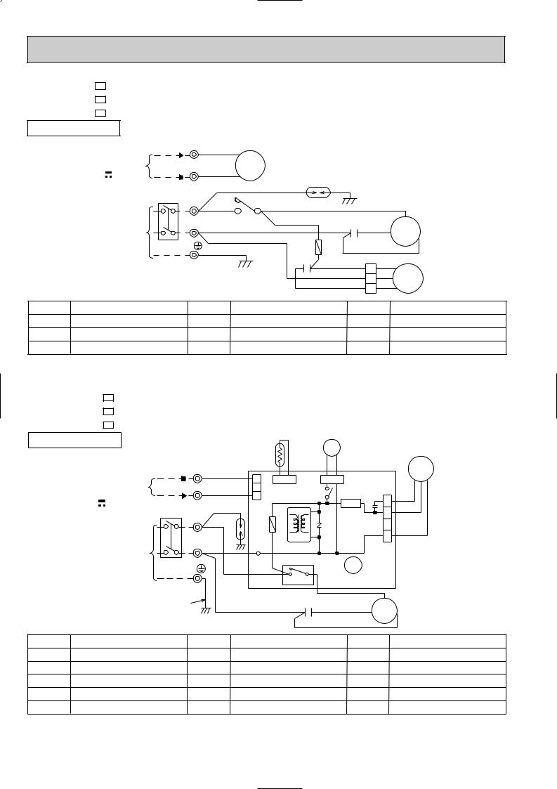
MU-C07TV - E1 |
|
|
|
|
|
|
|
MU-C09TV - E1 |
|
|
|
|
|
|
|
MU-C12TV - E1 |
MODELS WIRING DIAGRAM |
|
|
||||
OUTDOOR UNIT |
|
|
|
|
|
|
|
|
|
|
TB2 |
|
|
|
|
|
FROM |
|
2 |
WHT |
|
|
|
|
INDOOR UNIT |
|
|
|
|
|
|
|
CONNECTING |
1 |
BLK |
52C |
|
|
|
|
12V |
|
|
|
|
||
|
|
|
|
|
|
||
|
|
|
|
|
DSAR |
|
|
|
|
|
TB1 |
BRN |
|
|
|
|
|
CIRCUIT BREAKER |
52C |
|
|
||
|
|
L |
|
|
|
||
|
|
|
BRN |
WHT |
|
|
|
|
|
|
|
|
C |
||
|
|
|
|
|
NO COM WHT |
|
|
|
POWER SUPPLY |
N |
BLU |
C1 RED |
MC |
||
|
~ /N |
|
|
||||
|
230V |
PE |
|
F |
S |
R |
|
|
50Hz |
|
BLK |
|
|||
|
|
|
GRN/YLW |
|
|||
|
|
|
|
|
C2 WHT |
WHT 1 WHT |
|
|
|
|
|
|
|
BLU 2 BLK |
MF |
|
|
|
|
|
|
RED 3 RED |
|
SYMBOL |
|
NAME |
SYMBOL |
NAME |
SYMBOL |
NAME |
|
C1 |
COMPRESSOR CAPACITOR |
|
F |
FUSE(2A) |
TB1,TB2 |
TERMINAL BLOCK |
|
C2 |
OUTDOOR FAN CAPACITOR |
|
MC |
COMPRESSOR(INNER PROTECTOR) |
52C |
CONTACTOR |
|
DSAR |
SURGE ABSORBER |
|
MF |
OUTDOOR FAN MOTOR(INNER PROTECTOR) |
|
|
|
NOTE:1. About the indoor side electric wiring refer to the indoor unit electric wiring diagram for servicing. |
VG79B057H01 |
|||||
2.Use copper conductors only. (For field wiring) |
|
|||||
3. Symbols below indicate. |
|
|||||
/: Terminal block, |
|
|
|
|
: Connector |
|
|
|
|
|
|
||
MUH-C07TV - E1 MUH-C09TV - E1 MUH-C12TV - E1
OUTDOOR UNIT
MODELS WIRING DIAGRAM
RT61 |
21S4 |
|
TB2 |
|
|
FROM |
3 |
RED |
|
INDOOR UNIT |
|
|
|
N |
|
|
|
CONNECTING |
BLK |
|
|
|
|
||
12V |
|
|
|
CIRCUIT BREAKER TB1 BRN |
|||
|
L |
BRN |
DSAR |
|
|
||
|
|
|
|
POWER SUPPLY |
N BLU |
|
|
~ /N |
|
||
230V |
|
|
|
50Hz |
PE |
|
|
1 |
CN730 |
CN661 |
3 |
|
|
2 |
|
|
|
F61 |
IC881 |
|
|
TRANS |
BLKBLK
CN721
X62
SR61
NR61
MF
1RED
2WHT
C65
3
4 BLK
CN711
TAB20 |
52C |
X62 |
|
|
|
|
|
|
4 3 |
DEICER P.C. BOARD |
||
|
|
|
|
C1 |
|
WHT |
C |
|
GRN/YLW |
|
|
|
|
||
|
|
BLU |
RED |
MC |
|||
|
|
|
|
||||
|
|
|
|
|
|
||
|
|
|
|
|
BLK |
S |
R |
|
|
|
|
|
|
|
|
SYMBOL |
NAME |
SYMBOL |
|
NAME |
|
SYMBOL |
NAME |
C1 |
COMPRESSOR CAPACITOR |
MC |
COMPRESSOR(INNER PROTECTOR) |
TB1,TB2 |
TERMINAL BLOCK |
||
C65 |
OUTDOOR FAN CAPACITOR |
MF |
OUTDOOR FAN MOTOR(INNER PROTECTOR) |
X62 |
R.V. COIL RELAY |
||
DSAR |
SURGE ABSORBER |
NR61 |
VARISTOR |
|
|
21S4 |
R.V. COIL |
F61 |
FUSE(2A) |
RT61 |
DEFROST THERMISTOR |
52C |
CONTACTOR |
||
IC881 |
DC/DC CONVERTER |
SR61 |
SOLID STATE RELAY |
|
|
|
|
NOTE:1. About the indoor side electric wiring refer to the indoor unit electric wiring diagram for servicing. |
VG79B058H01 |
|||||
2.Use copper conductors only. (For field wiring) |
|
|||||
3. Symbols below indicate. |
|
|||||
/: Terminal block, |
|
|
|
|
: Connector |
|
|
|
|
|
|
||
14
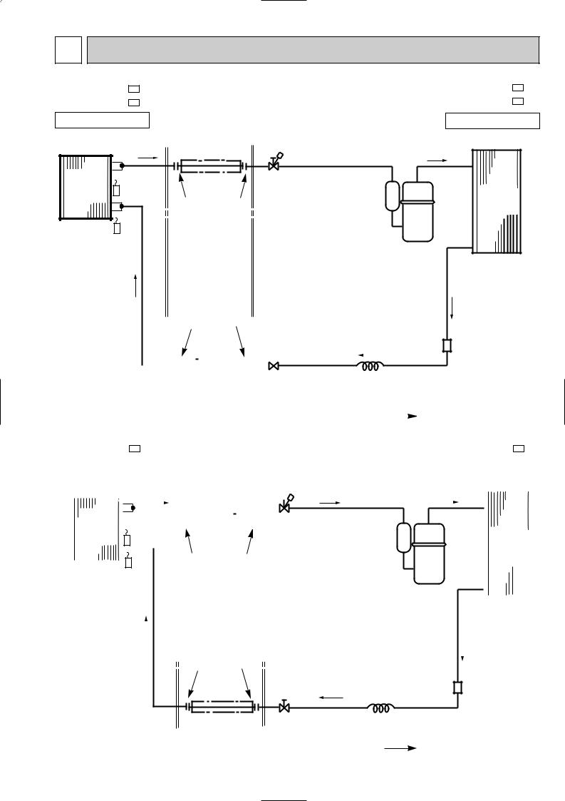
7 |
REFRIGERANT SYSTEM DIAGRAM |
|
|||
|
|
|
|
|
Unit:mm |
MSC-C07TV - E1 |
|
|
MU-C07TV - E1 |
||
MSC-C09TV - E1 |
|
|
MU-C09TV - E1 |
||
INDOOR UNIT |
Refrigerant pipe [9.52 |
|
OUTDOOR UNIT |
||
|
|
|
(Option) |
Stop valve |
|
|
|
|
(with heat insulator) |
|
|
|
|
|
(with service port) |
|
|
|
|
|
|
|
|
Indoor |
|
Indoor coil |
|
|
|
heat |
|
|
|
|
|
|
thermistor |
|
|
Outdoor |
|
exchanger |
|
|
|||
RT12 |
|
|
|||
|
|
Flared connection |
|
heat |
|
|
|
|
|
exchanger |
|
|
|
|
|
|
|
Room temperature |
|
|
|
||
thermistor |
|
|
|
|
Compressor |
RT11 |
|
|
|
|
|
|
|
|
|
|
|
|
|
|
|
|
|
|
|
Flared connection |
|
|
|
|
|
|
|
|
|
|
|
|
|
|
|
|
|
|
|
Strainer |
|||||||||||||||||||||||||||||||||||||||||||
|
|
|
|
|
|
|
|
|
|
|
|
|
|
|
|
|
|
|
|
|
|
|
|
|
|
|
|
||||||||||||||||||||||||||||||||||||||||||||||||||
|
|
|
|
|
|
|
|
|
|
|
|
|
|
|
|
|
|
|
|
|
|
|
|
|
|
|
|
|
|
|
|
|
|
|
|
|
|
|
|
|
|
|
|
|
|
|
|
|
|
|
|
|
|
|
|
|
|
|
|
|
|
|
|
|
|
|
|
||||||||||
|
|
|
|
|
|
|
|
|
|
|
|
|
|
|
|
|
|
|
|
|
|
|
|
|
|
|
|
|
|
|
|
|
|
|
|
|
|
|
|
|
|
|
|
|
|
|
|
|
|
|
|
|
|
|
|
|
|
|
|
|
|
|
|
|
|
|
|
||||||||||
|
|
|
|
|
|
|
|
|
|
|
|
|
|
|
|
|
|
|
|
|
|
|
|
|
|
|
|
|
|
|
|
|
|
|
|
|
|
|
|
|
|
|
|
|
|
|
|
|
|
|
|
|
|
|
|
|
|
|
|
|
|
|
|
|
|
|
|
|
|
|
|
|
|
|
|
|
|
|
|
|
|
|
|
|
|
|
|
|
|
|
|
|
|
|
|
|
|
|
|
|
|
|
|
|
|
|
|
|
|
|
|
|
|
|
|
|
|
|
|
|
|
|
|
|
|
|
|
|
|
|
|
|
|
|
|
|
|
|
Capillary tube |
|
|
|
|
|
|
|
|
|
|
|
|
|
|
|
|
|
|
|
|
|
|
|
|
|
|
|
|
|
|
|
|
|
|
|
|
|
|
|
|
|
|
|
|
|
|
|
|
|
|
|
|
|
|
|
|
|
|
|
|
|
|
|
|
|
|
|
|
|
|
|
|
|
|
|
|
|
|
|
|
|
|
|
|
|
|
|
|
|
|
|
|
||
|
|
|
|
|
|
|
|
|
|
|
Refrigerant pipe [6.35 |
|
|
|
|
|
|
|
[3.0x[1.4x600(MU-C07TV) |
||||||||||||||||||||||||||||||||||||||||||||||||||||||||||
|
|
|
|
|
|
|
|
|
|
|
|
|
|
|
|
|
|
[3.0x[1.4x750(MU-C09TV) |
|||||||||||||||||||||||||||||||||||||||||||||||||||||||||||
|
|
|
|
|
|
|
|
|
|
|
(Option) |
|
|
|
|
|
|
|
|||||||||||||||||||||||||||||||||||||||||||||||||||||||||||
|
|
|
|
|
|
|
|
|
|
|
|
|
|
|
|
|
|
|
|
|
|
|
|
|
|
|
|
|
|
|
|
|
|
|
|||||||||||||||||||||||||||||||||||||||||||
|
|
|
|
|
|
|
|
|
|
|
(with heat insulator) |
|
|
|
|
|
|
|
|
|
|
|
Refrigerant flow in cooling |
||||||||||||||||||||||||||||||||||||||||||||||||||||||
|
|
|
|
|
|
|
|
|
|
|
|
|
|
|
|
|
|
|
|
|
|
||||||||||||||||||||||||||||||||||||||||||||||||||||||||
|
|
|
|
|
|
|
|
|
|
|
|
|
|
|
|
|
|
|
|
|
|
|
|
|
|
|
|
|
|
|
|
|
|
|
|
|
|
|
|
|
|
|
|
|
|
|
|
|
|
|
|
|
|
|
|
|
|
|
|
|
|
|
|
|
|
|
|
|
|
|
Unit:mm |
||||||
MSC-C12TV - E1 |
|
|
|
|
|
|
|
|
|
|
|
|
|
|
|
|
|
|
|
|
|
|
|
|
|
|
|
|
|
|
|
|
|
|
|
|
|
|
|
|
|
|
|
|
|
|
|
|
|
|
|
|
|
|
|
|
|
|
|
|
MU-C12TV - E1 |
||||||||||||||||
INDOOR UNIT |
|
|
|
|
|
|
|
|
|
Refrigerant pipe [12.7 |
|
|
|
|
|
|
|
|
|
|
|
|
|
OUTDOOR UNIT |
|||||||||||||||||||||||||||||||||||||||||||||||||||||
|
|
|
|
|
|
|
|
|
|
|
|
|
|
|
|
(Option) |
|
|
|
|
|
|
|
|
|
|
|
|
|
|
|
|
|
|
|
|
|
|
|
|
|||||||||||||||||||||||||||||||||||||
|
|
|
|
|
|
|
|
|
|
|
|
|
|
|
|
|
|
|
|
|
|
|
|
|
|
|
|
|
|
|
|
|
|
|
|
|
|
|
|
||||||||||||||||||||||||||||||||||||||
|
|
|
|
|
|
|
|
|
|
|
|
|
|
|
|
(with heat insulator) |
|
|
|
|
|
|
|
|
|
|
|
|
|
|
|
|
|
|
|
|
|
|
|
|
|||||||||||||||||||||||||||||||||||||
|
|
|
|
|
|
|
|
|
|
|
|
|
|
|
|
|
|
|
|
|
|
|
|
|
|
|
|
|
|
|
|
|
|
|
|
|
|
|
|
|
|
|
|
|
|
|
|
|
|
|
|
|
|
|
|
|
|
|
|
|
|
|
|
|
|
|
|
|
|
|
|
|
|
|
|
|
|
|
|
|
|
|
|
|
|
|
|
|
|
|
|
|
|
|
|
|
|
|
|
|
|
|
|
|
|
|
|
|
|
|
|
|
|
|
|
|
|
|
|
|
|
|
|
|
|
|
|
|
|
|
|
|
|
|
|
|
|
|
|
|
|
|
|
|
|
|
|
|
|
|
|
|
|
|
|
|
|
|
|
|
|
|
|
|
|
|
|
|
|
|
|
|
|
|
|
|
|
|
|
|
|
|
|
|
|
|
|
|
|
|
|
|
|
|
|
|
|
|
|
|
|
|
|
|
|
|
|
|
|
|
|
|
|
|
|
|
|
|
|
|
|
|
|
|
|
|
|
|
|
|
|
|
|
|
|
Indoor |
|
Indoor coil |
|
|
|
|
|
|
|
|
|
|
|
|
|
|
|
|
|
|
|
|
|
|
|
|
|
|
|
|
|
|
|
|
|
|
|
|
|
|
|
|
Stop valve |
|
|
|
|
|
|
|
|
|
|
|
|
|
|
|
|||||||||||||||||
|
|
heat |
|
|
|
|
|
|
|
|
|
|
|
|
|
|
|
|
|
|
|
||||||||||||||||||||||||||||||||||||||||||||||||||||||||
|
|
exchanger |
|
thermistor |
|
|
|
(with service port) |
|
|
|
|
|
|
|
|
|
|
|
||||||||||||||||||||||||||||||||||||||||||||||||||||||||||
|
|
|
|
|
|
|
|
|
|
|
|
|
|
|
|
|
|
|
|
|
|
|
|
|
|
|
|
|
|
|
|
|
|
|
|
|
|
|
|
|
|
|
|
|
|
|
|
|
Outdoor |
|
|||||||||||||||||||||||||||
|
|
|
|
|
|
|
RT12 |
|
|
|
|
|
|
|
|
|
|
|
|
|
|
|
|
|
|
|
|
|
|
|
|
|
|
|
|
|
|
|
|
|
|
|
|
|
|
|
|
|
|
|
|
|
|
|
|
|
|
|
|
|
|
|
|
|
heat |
|
|
||||||||||
|
|
|
|
|
|
|
|
|
|
|
|
|
|
|
|
|
|
Flared connection |
|
|
|
|
|
|
|
|
|
|
|
|
|
|
|
|
|
|
|
exchanger |
|
|
|||||||||||||||||||||||||||||||||||||
|
|
|
|
|
|
|
|
|
|
|
|
|
|
|
|
|
|
|
|
|
|
|
|
|
|
|
|
|
|
|
|
|
|
|
|
|
|
||||||||||||||||||||||||||||||||||||||||
|
|
|
|
|
|
|
|
|
|
|
|
|
|
|
|
|
|
|
|
|
|
|
|
|
|
|
|
|
|
|
|
|
|
|
|
|
|
|
|
|
|
|
|
||||||||||||||||||||||||||||||||||
|
Room temperature |
|
|
|
|
|
|
|
|
|
|
|
|
|
|
|
|
|
|
|
|
|
|
|
|
|
|
|
|
|
|
|
|
|
|
|
|
|
|
|
|
|
|
|
|
|
|
|
|
|
|
|
|
|
|
|
|
|
|
|
|
|
|
|
|
|
|
|
|
|
|
|
|||||
|
thermistor |
|
|
|
|
|
|
|
|
|
|
|
|
|
|
|
|
|
|
|
|
|
|
|
|
|
|
|
|
|
|
|
|
|
|
|
|
|
|
|
|
|
|
|
|
|
|
|
|
|
|
|
|
|
|
|
|
|
|
|
|
Compressor |
|
|
|
|
|
|
|
|
|||||||
|
RT11 |
|
|
|
|
|
|
|
|
|
|
|
|
|
|
|
|
|
|
|
|
|
|
|
|
|
|
|
|
|
|
|
|
|
|
|
|
|
|
|
|
|
|
|
|
|
|
|
|
|
|
|
|
|
|
|
|
|
|
|
|
|
|
|
|
|
|
|
|
||||||||
|
|
|
|
|
|
|
|
|
|
|
|
|
|
|
|
|
|
|
|
|
|
|
|
|
|
|
|
|
|
|
|
|
|
|
|
|
|
|
|
|
|
|
|
|
|
|
|
|
|
|
|
|
|
|
|
|
|
|
|
|
|
|
|
|
|
|
|
|
|
|
|
|
|
|
|||
|
|
|
|
|
|
|
|
|
|
|
|
|
|
|
|
|
|
|
|
|
|
|
|
|
|
|
|
|
|
|
|
|
|
|
|
|
|
|
|
|
|
|
|
|
|
|
|
|
|
|
|
|
|
|
|
|
|
|
|
|
|
|
|
|
|
|
|
|
|
|
|
|
|
|
|
|
|
|
|
|
|
|
|
|
|
|
|
|
|
|
|
|
|
|
|
|
|
|
|
|
|
|
|
|
|
|
|
|
|
|
|
|
|
|
|
|
|
|
|
|
|
|
|
|
|
|
|
|
|
|
|
|
|
|
|
|
|
|
|
|
|
|
|
|
|
|
|
|
|
|
|
|
|
|
|
|
|
|
|
|
|
|
|
|
|
|
|
|
|
|
|
|
|
|
|
|
|
|
|
|
|
|
|
|
|
|
|
|
|
|
|
|
|
|
|
|
|
|
|
|
|
|
|
|
|
|
|
|
|
|
|
|
|
|
|
|
|
|
|
|
|
|
|
|
|
|
|
|
|
|
|
|
|
|
|
|
|
|
|
|
|
|
|
|
|
|
|
|
|
|
|
|
|
|
|
|
|
|
|
|
|
|
|
|
|
|
|
|
|
|
|
|
|
|
|
|
|
|
|
|
|
|
|
|
|
|
|
|
|
|
|
|
|
|
|
|
|
|
|
|
|
|
|
|
|
|
|
|
|
|
|
Flared connection |
|
|
|
|
|
Stop valve |
Strainer |
|
|
|
|
|
|
|
Capillary tube |
Refrigerant pipe |
[6.35 |
|
[3.0x[1.6x600 |
|
|
||
(Option) |
|
|
Refrigerant flow in cooling |
(with heat insulator) |
|
|
|
|
|
15 |
|
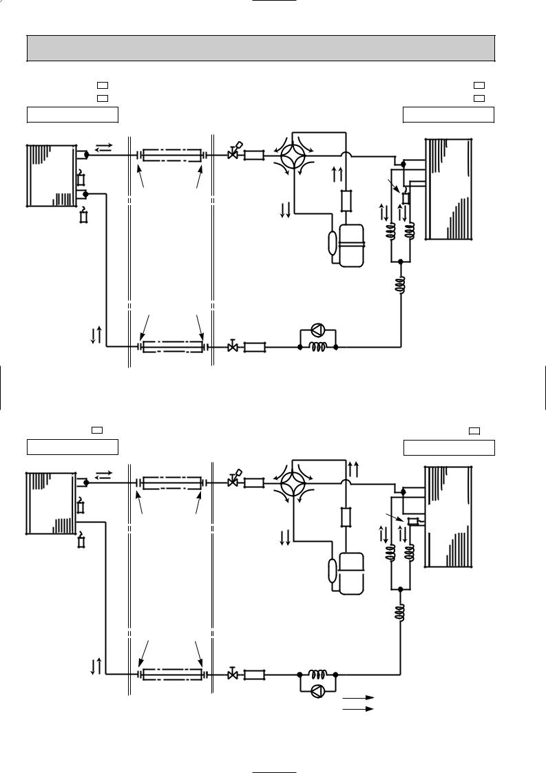
MSC-C07TV - E1 MSC-C09TV - E1
INDOOR UNIT
Indoor |
Indoor coil |
heat |
thermistor |
exchanger |
RT12 |
Room temperature thermistor
RT11
Refrigerant pipe [ 9.52 (Option)
(with heat insulator)
Muffler
|
Stop valve |
|
(with service |
Flared connection |
port) |
Unit:mm
MUH-C07TV - E1
MUH-C09TV - E1
OUTDOOR UNIT
4-way valve
Defrost |
|
thermistor |
Outdoor |
RT61 |
heat |
Strainer |
exchanger |
Flared connection
Refrigerant pipe [6.35 (Option)
(with heat insulator)
Compressor
Capillary tube [3.0x[1.6x750(MUH-C07TV) [3.0x[1.8x400(MUH-C09TV)
|
Check valve |
|
Strainer |
|
|
Stop valve |
Capillary tube |
|
[3.0x[1.4x700(MUH-C07TV) |
||
|
||
|
[3.0x[1.4x650(MUH-C09TV) |
Capillary tube [3.0x[1.4x800 (2 pcs) (MUH-C07TV) [3.0x[1.4x500 (2 pcs) (MUH-C09TV)
R.V. coil heating ON cooling OFF
 Refrigerant flow in cooling
  Refrigerant flow in heating
Unit:mm
MSC-C12TV - E1 |
MUH-C12TV - E1 |
INDOOR UNIT Refrigerant pipe [12.7 |
4-way valve |
OUTDOOR UNIT |
(Option) |
|
|
|
|
|
|
(with heat insulator) |
Muffler |
|
|
|
|
|
|
|
|
|
|
Indoor |
Indoor coil |
|
Stop valve |
|
Defrost |
|
heat |
thermistor |
|
|
|
||
|
(with service port) |
|
thermistor |
Outdoor |
||
exchanger |
RT12 |
|
Strainer |
|||
Flared connection |
|
RT61 |
heat |
|||
|
|
|
|
|||
|
|
|
|
|
|
exchanger |
Room temperature
thermistor
RT11  Capillary tube [3.0x[1.4x500(2pcs)
Compressor |
Capillary tube |
|
[3.0x[1.8x400 |
Flared connection
Capillary tube
Strainer [3.0x[1.6x800 R.V. coil heating ON
cooling OFF
|
Stop valve |
Refrigerant flow in cooling |
|
Refrigerant pipe [6.35 |
|
||
Check |
Refrigerant flow in heating |
||
(Option) |
valve |
||
|
|||
(with heat insulator) |
|
||
|
|
16

MAX. REFRIGERANT PIPING LENGTH
|
Refrigerant piping |
Piping size O.D : mm |
Length of connecting pipe : m |
|||
Model |
Max. length : m |
|||||
|
|
|
|
|||
|
A |
Gas |
Liquid |
Indoor unit |
Outdoor unit |
|
{MSC-C07TV - E1 MU-C07TV - E1
|
|
|
|
|
10 |
9.52 |
|
Gas 0.43 |
Gas 0 |
|
MSC-C09TV - |
|
|
|
|
|
|||||
|
E1 |
|
|
|
|
|
|
|||
{MU-C09TV - |
|
|
|
|
|
6.35 |
|
|
|
|
|
|
|
|
|
|
|
|
|
||
E1 |
|
|
|
|
|
|
||||
|
|
|
|
|
|
|
|
Liquid 0.5 |
Liquid 0 |
|
MSC-C12TV - |
|
|
|
|
|
|
||||
E1 |
|
|
|
|
|
|
||||
{MU-C12TV - |
|
|
|
|
15 |
12.7 |
|
|
|
|
|
|
|
|
|
|
|
|
|||
E1 |
|
|
|
|
|
|||||
|
|
|
|
|
|
|
|
|
|
|
|
|
|
|
|
|
|
|
|
|
|
|
|
|
|
|
Refrigerant piping |
Piping size O.D : mm |
Length of connecting pipe : m |
|
||
Model |
|
|
|
|
Max. length : m |
|
||||
|
|
|
|
|
|
|
|
|
||
|
|
|
|
|
A |
Gas |
Liquid |
Indoor unit |
Outdoor unit |
|
{MSC-C07TV - MUH-C07TV -
{MSC-C09TV - MUH-C09TV -
{MSC-C12TV - MUH-C12TV -
E1
E1
E1
E1
E1
E1
10 |
9.52 |
Gas 0.43 |
Gas 0 |
|
|
6.35 |
|
|
|
Liquid 0.5 |
Liquid 0 |
15 |
12.7 |
|
|
MAX. HEIGHT DIFFERENCE
Indoor unit
w Height difference should be within |
|
Refrigerant Piping |
|
5m regardless of which unit, |
|
||
w Max. Height |
Max.length |
||
indoor or outdoor position is high. |
|||
A |
|||
difference 5m |
|||
|
Outdoor unit
ADDITIONAL REFRIGERANT CHARGE(R407C : g)
Model |
|
Outdoor unit precharged |
|
Refrigerant piping length (one way) |
|
|
7m |
10m |
15m |
||
|
|
|
|||
MSC-C07TV - E1 |
770 |
|
|
|
|
{MU-C07TV - |
E1 |
|
|
|
|
|
|
|
|
||
MSC-C09TV - E1 |
|
0 |
45 |
|
|
{MU-C09TV - |
E1 |
880 |
|
||
|
|
|
|||
MSC-C12TV - E1 |
|
|
|
|
|
{MU-C12TV - |
E1 |
900 |
|
|
120 |
Calculation : Xg=15g/m x(Refrigerant piping length (m) -7)
Model |
|
|
|
|
Outdoor unit precharged |
|
Refrigerant piping length (one way) |
|
||
|
|
|
|
7m |
|
10m |
|
15m |
||
|
|
|
|
|
|
|||||
|
|
|
|
|
|
|
|
|||
MSC-C07TV - |
|
|
|
|
|
|
|
|
|
|
|
E1 |
|
|
|
|
|
|
|
||
{MUH-C07TV - |
|
|
|
|
900 |
|
|
|
|
|
|
|
|
|
|
|
|
|
|
||
|
|
E1 |
|
|
|
|
|
|
||
MSC-C09TV - |
|
|
|
|
|
|
|
|
|
|
|
|
E1 |
|
|
|
|
|
|
|
|
{ MUH-C09TV - |
|
|
|
|
1000 |
0 |
|
75 |
|
|
|
|
|
|
|
|
|
||||
|
|
E1 |
|
|
|
|
|
|
||
MSC-C12TV - |
|
|
|
|
|
|
|
|
||
E1 |
|
|
|
|
|
|
|
|||
{MUH-C12TV - |
|
|
|
|
1250 |
|
|
|
|
200 |
|
|
|
|
|
|
|
|
|||
|
|
E1 |
|
|
|
|
|
|||
|
|
|
|
|
|
|
|
|
|
|
Calculation : Xg=25g/m x(Refrigerant piping length (m) -7)
17
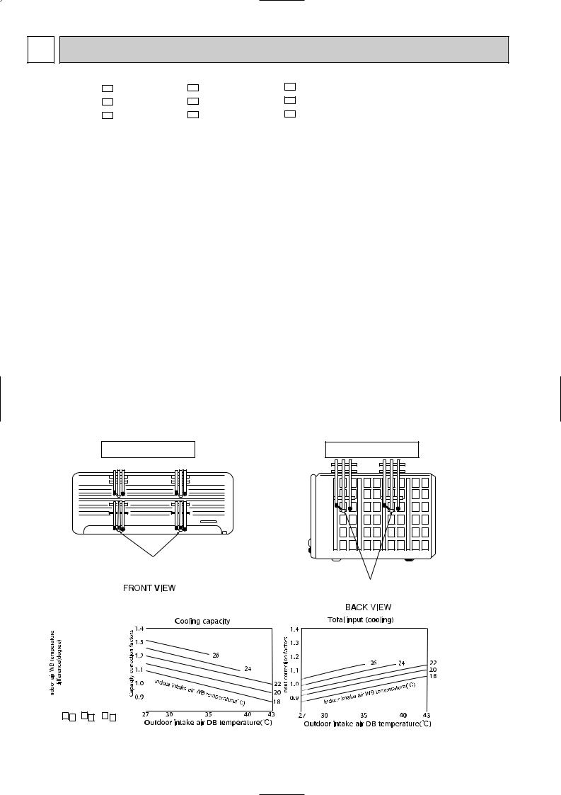
8 PERFORMANCE CURVES
MSC-C07TV - E1 MSC-C09TV - E1 MSC-C12TV - E1
MU-C07TV - E1 MU-C09TV - E1 MU-C12TV - E1
MUH-C07TV - E1 MUH-C09TV - E1 MUH-C12TV - E1
The standard data contained in these specifications apply only to the operation of the air conditioner under normal conditions. Since operating conditions vary according to the areas where these units are installed. The following information has been provided to clarify the operating characteristics of the air conditioner under the conditions indicated by the performance curve.
(1)GUARANTEED VOLTAGE
Rated voltage : 198 ~ 264V, 50Hz
(2)AIR FLOW
Air flow should be set at MAX.
(3) MAIN READINGS
(1) |
Indoor intake air wet-bulb temperature : |
°CWB |
} Cooling |
|
(2) |
Indoor outlet air wet-bulb temperature : |
°CWB |
||
(3) |
Outdoor intake air dry-bulb temperature : |
°CDB |
||
(4) |
Total input: |
W |
} |
|
(5) |
Indoor intake air dry-bulb temperature : |
°CDB |
Heating <MUH-C07/C09/C12TV> |
|
(6) |
Outdoor intake air wet-bulb temperature : |
°CWB |
||
(7) |
Total input : |
W |
|
|
Indoor air wet/dry-bulb temperature difference on the left side of the chart on this page and next page shows the difference between the indoor intake air wet/dry-bulb temperature and the indoor outlet air wet/dry-bulb temperature for your reference at service.
How to measure the indoor air wet-bulb/dry-bulb temperature difference
1.Attach at least 2 sets of wet-and dry-bulb thermometers to the indoor air intake as shown in the figure, and at least 2 sets of wet-and dry-bulb thermometers to the indoor air outlet. The thermometers must be attached to the position where air speed is high.
2.Attach at least 2 sets of wet-and dry-bulb thermometers to the outdoor air intake. Cover the thermometers to prevent direct rays of the sun.
3.Check that the air filter is cleaned.
4.Open windows and doors of room.
5.Press the EMERGENCY OPERATION switch once(twice) to start the EMERGENCY COOL(HEAT<MUH-C07/C09/C12 TV>) MODE.
6.When system stabilizes after more than 15 minutes, measure temperature and take an average temperature.
7.10 minutes later, measure temperature again and check that the temperature does not change.
INDOOR UNIT |
OUTDOOR UNIT |
Wet-and dry-bulb thermometers
Wet-and dry-bulb thermometers
9.1 |
|
|
|
10.2 |
11.8 |
|
|
|
|
|
|
|
|
|
|
|
|
|
|
|
|
|
|
|
|
|
|
|
|
|
|
|
|
|
|
|
|
|
|
|
|
|
|
|
|
|
|
|
|
|
|
|
|
|
|
|
|
|||
|
|
|
|
|
|
|
|
|
|
|
|
|
|
|
|
|
|
|
|
|
|
|
|
|
|
|
|
|
|
|
|
|
|
|
|
|
|
|
|
|
|
|
|
|
|
|
|
|
|
|
|
|
|
|
||||||
8.4 |
|
|
|
|
9.310.8 |
|
|
|
|
|
|
|
|
|
|
|
|
|
|
|
|
|
|
|
|
|
|
|
|
|
|
|
|
|
|
|
|
|
|
|
|
|
|
|
|
|
|
|
|
|
|
|
|
|
|
|
|
|||
|
|
|
|
|
|
|
|
|
|
|
|
|
|
|
|
|
|
|
|
|
|
|
|
|
|
|
|
|
|
|
|
|
|
|
|
|
|
|
|
|
|
|
|
|
|
|
|
|
|
|
|
|
|
|
|
|||||
|
|
|
|
|
|
|
|
|
|
|
|
|
|
|
|
|
|
|
|
|
|
|
|
|
|
|
|
|
|
|
|
|
|
|
|
|
|
|
|
|
|
|
|
|
|
|
|
|
|
|
|
|
|
|
|
|||||
7.6 |
|
|
|
|
8.5 |
9.8 |
|
|
|
|
|
|
|
|
|
|
|
|
|
|
|
|
|
|
|
|
|
|
|
|
|
|
|
|
|
|
|
|
|
|
|
|
|
|
|
|
|
|
|
|
|
|
|
|
|
|
|
|
||
|
|
|
|
|
|
|
|
|
|
|
|
|
|
|
|
|
|
|
|
|
|
|
|
|
|
|
|
|
|
|
|
|
|
|
|
|
|
|
|
|
|
|
|
|
|
|
|
|
|
|
|
|
|
|
||||||
|
|
|
|
|
|
|
|
|
|
|
|
|
|
|
|
|
|
|
|
|
|
|
|
|
|
|
|
|
|
|
|
|
|
|
|
|
|
|
|
|
|
|
|
|
|
|
|
|
|
|
|
|
|
|
||||||
|
|
|
|
|
|
|
|
|
|
|
|
|
|
|
|
|
|
|
|
|
|
|
|
|
|
|
|
|
|
|
|
|
|
|
|
|
||||||||||||||||||||||||
6.9 |
|
|
|
|
7.7 |
8.8 |
|
|
|
|
|
|
|
|
|
|
|
|
|
|
|
|
|
|
|
|
|
|
|
|
|
|
|
|
|
|
|
|
|
|
|
|
|
|
|
|
|
|
|
|
|
|
|
|
|
|
|
|
||
6.2 |
|
|
|
6.9 |
7.9 |
|
|
|
|
|
|
|
|
|
|
|
|
|
|
|
|
|
|
|
|
|
|
|
|
|
|
|
|
|
|
|
|
|
|
|
|
|
|
|
|
|
|
|
|
|
|
|
|
|
|
|
|
|||
|
|
|
|
|
|
|
|
|
|
|
|
|
|
|
|
|
|
|
|
|
|
|
|
|
|
|
|
|
|
|
|
|
|
|
|
|
|
|
|
|
|
|
|
|
|
|
|
|
|
|
|
|
|
|
|
|||||
|
|
5.5 |
|
|
|
|
6.1 |
7.0 |
|
|
|
|
|
|
|
|
|
|
|
|
|
|
|
|
|
|
|
|
|
|
|
|
|
|
|
|
|
|
|
|
|
|
|
|
|
|
|
|
|
|
|
|
|
|
|
|
|
|
|
|
|
|
|
|
|
|
|
|
|
|
|
|
|
|
|
|
|
|
|
|
|
|
|
|
|
|
|
|
|
|
|
|
|
|
|
|
|
|
|
|
|
|
|
|
|
|
|
|
|
|
|
|
|
|
|
|
|
||||
|
|
|
|
|
|
|
|
|
|
|
|
|
|
|
|
|
|
|
|
|
|
|
|
|
|
|
|
|
|
|
|
|
|
|
|
|
|
|
|
|
|
|
|
|
|
|
|
|
|
|
|
|
|
|
|
|
||||
|
|
|
|
|
|
|
|
|
|
|
|
|
|
|
|
|
|
|
|
|
|
|
|
|
|
|
|
|
|
|
|
|
|
|
|
|
|
|
|
|
|
|
|
|
|
|
|
|
|
|
|
|
|
|
|
|
|
|||
|
|
|
|
|
|
|
|
|
|
|
|
|
|
|
|
|
|
|
|
|
|
|
|
|
|
|
|
|
|
|
|
|
|
|
|
|
|
|
|
|
|
|
|
|
|
|
|
|
|
|
|
|
|
|
|
|
||||
|
|
|
|
|
|
|
|
|
|
|
|
|
|
|
|
|
|
|
|
|
|
|
|
|
|
|
|
|
|
|
|
|
|
|
|
|
|
|
|
|
|
|
|
|
|
|
|
|
|
|
|
|
|
|
|
|
||||
|
|
|
|
|
|
|
|
|
|
|
|
|
|
|
|
|
|
|
|
|
|
|
|
|
|
|
|
|
|
|
|
|
|
|
|
|
|
|
|
|
|
|
|
|
|
|
|
|
|
|
|
|
|
|
|
|
|
|
|
|
|
|
MSC-C07TV - E1 (MU-C07TV - E1 ) |
|
|
MSC-C09TV - E1 (MU-C09TV - E1 ) |
MSC-C12TV - E1 (MU-C12TV - E1 ) |
|
|
|
|
|
|
|
|
|
|
|
|
|
|
|
|
|
|
|
|
|
|
|
|
|
|
|
|
|
|
|
|||||||||||||||||||||||
18
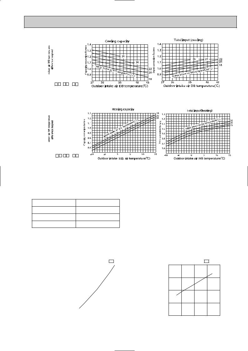
|
8.9 |
|
|
|
|
|
|
|
|
|
10.4 |
11.4 |
|
|
|
|
|
|
|
|
|
|
|
|||||
|
|
|
|
|
|
|
|
|
|
|
|
|
|
|
|
|
|
|
|
|
||||||||
|
8.2 |
|
|
|
|
|
|
|
|
|
|
9.5 |
10.4 |
|
|
|
|
|
|
|
|
|
|
|
||||
|
|
|
|
|
|
|
|
|
|
|
|
|
|
|
|
|
|
|
|
|
|
|||||||
|
|
|
|
|
|
|
|
|
|
|
|
|
|
|
|
|
|
|
|
|
|
|||||||
|
7.4 |
|
|
|
|
|
|
|
|
|
|
8.7 |
9.5 |
|
|
|
|
|
|
|
|
|
|
|
||||
|
|
|
|
|
|
|
|
|
|
|
|
|
|
|
|
|
|
|
|
|
|
|||||||
|
|
|
|
|
|
|
|
|
|
|
|
|
|
|
|
|
|
|
|
|
|
|||||||
|
6.7 |
|
|
|
|
|
|
|
|
|
|
7.8 |
8.5 |
|
|
|
|
|
|
|
|
|
|
|
||||
|
|
|
|
|
|
|
|
|
|
|
|
|
|
|
|
|
|
|
|
|
|
|||||||
|
|
|
|
|
|
|
|
|
|
|
|
|
|
|
|
|
|
|
|
|
|
|||||||
|
6.0 |
|
|
|
|
|
|
|
|
|
|
7.0 |
7.6 |
|
|
|
|
|
|
|
|
|
|
|
||||
|
|
|
|
|
|
|
|
|
|
|
|
|
|
|
|
|
|
|
|
|
|
|||||||
|
|
|
|
|
|
|
|
|
|
|
|
|
|
|
|
|
|
|
|
|
|
|||||||
|
|
|
|
5.4 |
|
|
|
|
|
|
|
|
|
|
6.2 |
6.8 |
|
|
|
|
|
|
|
|
|
|
|
|
|
|
|
|
|
|
|
|
|
|
|
|
|
|
|
|
|
|
|
|
|
|
|
|
|
||||
|
|
|
|
|
|
|
|
|
|
|
|
|
|
|
|
|
||||||||||||
|
|
|
|
|
|
|
|
|
|
|
|
|
|
|
|
|
|
|
|
|
|
|||||||
|
|
|
|
|
|
|
|
|
|
|
|
|
|
|
|
|
|
|
|
|
|
|
|
|
|
|
|
|
|
|
|
|
|
|
|
|
|
|
|
|
|
|
|
|
|
|
|
|
|
|
|
|
|
|
|
|
|
|
|
|
|
|
MSC-C07TV - E1 (MUH-C07TV - E1 ) |
MSC-C09TV - E1 |
(MUH-C09TV - E1 ) |
MSC-C12TV - E1 (MUH-C12TV - E1 ) |
|
|
|
|
|
|
||||||||||||||
|
|
|
|
|
|
|
|
|
|
|
|
|||||||||||||||||
|
19.5 |
|
|
|
|
|
|
|
|
|
24.9 28.6 |
|
|
|
|
|
|
|
|
|
|
|
||||||
|
18.0 |
|
|
|
|
|
|
|
|
|
23.0 26.4 |
|
|
|
|
|
|
|
|
|
|
|
||||||
|
|
|
|
|
|
|
|
|
|
|
|
|
|
|
|
|||||||||||||
|
16.5 |
|
|
|
|
|
|
|
|
|
21.1 24.2 |
|
|
|
|
|
|
|
|
|
|
|
||||||
|
|
|
|
|
|
|
|
|
|
|
|
|
|
|
|
|
|
|
|
|
||||||||
|
|
|
|
|
|
|
|
|
|
|
|
|
|
|
|
|||||||||||||
|
15.0 |
|
|
|
|
|
|
|
|
|
19.2 22.0 |
|
|
|
|
|
|
|
|
|
|
|
||||||
|
|
|
|
|
|
|
|
|
|
|
|
|
|
|
|
|
|
|
|
|
||||||||
|
|
|
|
|
|
|
|
|
|
|
|
|
|
|
|
|||||||||||||
|
13.5 |
|
|
|
|
|
|
|
|
|
17.2 19.8 |
|
|
|
|
|
|
|
|
|
|
|
||||||
|
|
|
|
|
|
|
|
|
|
|
|
|
|
|
|
|
|
|
|
|
||||||||
|
|
|
|
|
|
|
|
|
|
|
|
|
|
|
|
|
|
|
||||||||||
|
12.0 |
|
|
|
|
|
|
|
|
|
15.3 17.6 |
|
|
|
|
|
|
|
|
|
|
|
||||||
|
|
|
|
|
|
|
|
|
|
|
|
|
|
|
|
|
|
|
|
|
||||||||
|
|
|
|
|
|
|
|
|
|
|
|
|
|
|
|
|
|
|
|
|
||||||||
|
|
|
10.5 |
|
|
|
|
|
|
|
|
|
13.4 15.4 |
|
|
|
|
|
|
|
|
|
|
|
||||
|
|
|
|
|
|
|
|
|
|
|
|
|
|
|
|
|
|
|
|
|
|
|
||||||
|
|
|
|
|
|
|
|
|
|
|
|
|
|
|
|
|
|
|
|
|
|
|||||||
|
9.0 |
|
|
|
|
|
|
|
|
|
11.5 13.2 |
|
|
|
|
|
|
|
|
|
|
|
||||||
|
|
|
|
|
|
|
|
|
|
|
|
|
|
|
|
|
|
|
|
|
||||||||
|
|
|
|
|
|
|
|
|
|
|
|
|
|
|
|
|
|
|||||||||||
|
|
|
|
|
|
|
|
|
|
|
|
|
|
|
|
|
|
|
|
|
|
|
|
|
||||
|
|
|
|
|
|
|
|
|
|
|
|
|
|
|
|
|
|
|
|
|
|
|
||||||
|
|
|
|
|
MSC-C07TV - E1 (MUH-C07TV - E1 ) |
MSC-C09TV - E1 |
(MUH-C09TV - E1 ) |
MSC-C12TV - E1 (MUH-C12TV - E1 ) |
|
|
|
|
|
|||||||||||||||
NOTE:The above curves are for the heating operation without any frost.
OUTDOOR LOW PRESSURE AND OUTDOOR UNIT CURRENT COOL operation
Both indoor and outdoor unit are under the same temperature/humidity condition.
Dry-bulb temperature |
Relative humidity(%) |
20 |
50 |
25 |
60 |
30 |
70 |
Air flow should be set at MAX.
The unit of pressure has been changed to MPa on the international system of units(SI unit system). The conversion factor is : 1(MPa[Gage]) =10.2(kgf/f[Gage])
(kgf/F[Gage])(MPa[Gage]) MU-C07TV - E1
|
7 |
0.7 |
|
|
|
|
|
|
|
|
pressurelow |
|
|
|
|
|
230V |
|
|||
|
|
|
|
|
|
|
|
|||
|
|
|
|
|
|
|
|
|
||
5 |
0.5 |
|
|
|
|
|
|
|
||
Outdoor |
6 |
0.6 |
|
|
|
|
|
|
|
|
|
|
|
|
|
|
|
|
|
||
|
|
|
|
|
|
|
|
|
|
|
|
|
|
|
|
|
|
|
|
|
|
4 |
|
0.4 |
|
|
|
|
|
|
|
|
|
|
|
|
|
|
|
|
|
||
|
|
0.3 |
|
|
|
|
|
|
|
|
|
3 |
|
|
|
|
|
|
|
|
|
|
|
|
|
|
|
|
|
|
||
|
15 18 20 |
25 |
30 32 35(:) |
|||||||
|
|
|||||||||
|
|
50 |
60 |
70(%) |
|
|||||
Ambient temperature(˚C)
Ambient humidity(%)
19
Outdoor unit current (A)
MU-C07TV - E1
3.5
230V
3.0
2.5
2.0
1.5 |
|
30 32 |
35(:) |
15 18 20 |
25 |
||
50 |
60 |
70(%) |
|
Ambient temperature(˚C)
Ambient humidity(%)
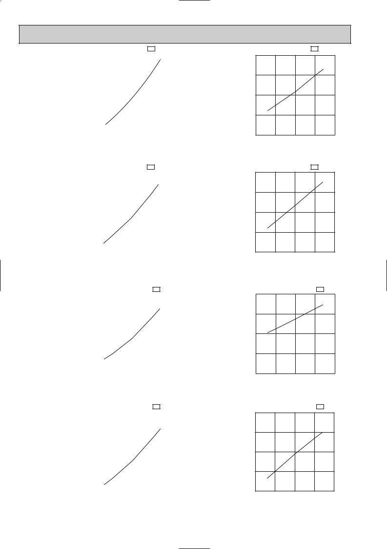
(kgf/F[Gage])(MPa[Gage]) MU-C09TV - E1
|
7 |
0.7 |
|
|
|
|
|
|
|
|
|
|
|
|
||||||||
pressurelow |
|
|
|
|
|
|
|
230V |
|
|||||||||||||
|
|
|
|
|
|
|
|
|
|
|
|
|
|
|
|
|||||||
|
|
|
|
|
|
|
|
|
|
|
|
|
|
|
|
|
|
|||||
5 |
|
0.5 |
|
|
|
|
|
|
|
|
|
|
|
|
||||||||
Outdoor |
6 |
|
0.6 |
|
|
|
|
|
|
|
|
|
|
|
|
|||||||
|
|
|
|
|
|
|
|
|
|
|
|
|
|
|
|
|
|
|
|
|
||
|
|
|
|
|
|
|
|
|
|
|
|
|
|
|
|
|
|
|
|
|
|
|
|
|
|
|
|
|
|
|
|
|
|
|
|
|
|
|
|
|
|
|
|
|
|
4 |
|
|
|
|
|
|
|
|
0.4 |
|
|
|
|
|
|
|
|
|
|
|
|
|
|
|
|
|
|
|
|
|
|
|
|
|
|
|
|
|
|
|
|
|
|
||
|
|
|
|
|
|
|
0.3 |
|
|
|
|
|
|
|
|
|
|
|
|
|||
|
3 |
|
|
|
|
|
|
|
|
|
|
|
|
|
|
|
|
|||||
|
|
|
|
|
|
|
|
|
|
|
|
|
30 32 |
|
|
|
|
|||||
|
|
15 |
18 20 |
25 |
35(:) |
|||||||||||||||||
|
|
|
||||||||||||||||||||
|
|
|
|
|
|
|
|
|
|
|
|
|
50 |
60 |
70(%) |
|
|
|
|
|||
|
|
|
|
|
|
|
|
|
|
|
|
Ambient temperature(˚C) |
|
|
|
|
||||||
|
|
|
|
|
|
|
|
|
|
|
|
Ambient humidity(%) |
|
|
|
|
||||||
(kgf/F[Gage])(MPa[Gage]) |
MU-C12TV - E1 |
|
|
|
|
|||||||||||||||||
|
7 |
|
|
0.7 |
|
|
|
|
|
|
|
|
|
|
|
|
||||||
pressure |
|
|
|
|
|
|
|
|
|
|
|
|
|
|
|
|
230V |
|
|
|
||
|
|
|
|
|
|
|
|
|
|
|
|
|
|
|
|
|
|
|
|
|||
6 |
|
|
|
0.6 |
|
|
|
|
|
|
|
|
|
|
|
|
||||||
low |
|
|
|
|
|
|
|
|
|
|
|
|
|
|
|
|||||||
|
|
|
|
|
0.5 |
|
|
|
|
|
|
|
|
|
|
|
|
|||||
5 |
|
|
|
|
|
|
|
|
|
|
|
|
|
|
|
|
|
|||||
Outdoor |
|
|
|
|
|
|
|
|
|
|
|
|
|
|
|
|
|
|||||
|
|
|
|
|
|
|
|
|
|
|
|
|
|
|||||||||
4 |
|
|
|
|
0.4 |
|
|
|
|
|
|
|
|
|
|
|
|
|||||
|
|
|
|
|
|
|
|
|
|
|
|
|
|
|
|
|
||||||
|
|
|
|
|
|
|
|
|
|
|
|
|
|
|
||||||||
|
3 |
|
|
|
0.3 |
|
|
|
|
|
|
|
|
|
|
|
|
|||||
|
|
|
|
|
|
18 20 |
|
|
30 32 |
35(:) |
||||||||||||
|
|
15 |
25 |
|||||||||||||||||||
|
|
|
||||||||||||||||||||
|
|
|
|
|
|
|
|
|
|
|
|
|
50 |
60 |
70(%) |
|
|
|
|
|||
|
|
|
|
|
|
|
|
|
|
|
|
Ambient temperature(˚C) |
|
|
|
|
||||||
|
|
|
|
|
|
|
|
|
|
|
|
Ambient humidity(%) |
|
|
|
|
||||||
(kgf/F[Gage])(MPa[Gage]) |
MUH-C07TV - E1 |
|
|
|
|
|||||||||||||||||
|
8 |
|
0.8 |
|
|
|
|
|
|
|
|
|
|
|
|
|||||||
pressure |
0.6 |
|
|
|
|
|
|
|
230V |
|
|
|||||||||||
|
|
|
|
|
|
|
|
|
|
|||||||||||||
|
|
|
|
|
|
|
|
|
|
|
|
|
|
|||||||||
|
7 |
0.7 |
|
|
|
|
|
|
|
|
|
|
|
|
||||||||
|
|
|
|
|
|
|
|
|
|
|
|
|
||||||||||
|
|
|
|
|
|
|
|
|
|
|
|
|
|
|
|
|
|
|
|
|
||
low |
6 |
|
|
|
|
|
|
|
|
|
|
|
|
|
|
|
|
|
|
|
|
|
|
|
|
|
|
|
|
|
|
|
|
|
|
|
|
|
|
|
|
|
|||
|
0.5 |
|
|
|
|
|
|
|
|
|
|
|
|
|||||||||
|
|
|
|
|
|
|
|
|
|
|
|
|
|
|||||||||
Outdoor |
4 |
|
|
|
|
|
|
|
|
|
|
|
|
|||||||||
|
|
|
|
|
|
|
|
|
|
|
|
|||||||||||
0.4 |
|
|
|
|
|
|
|
|
|
|
|
|
||||||||||
|
5 |
|
|
|
|
|
|
|
|
|
|
|
|
|
|
|
|
|
|
|
|
|
|
|
|
|
|
|
|
|
|
|
|
|
|
|
|
|
|
|
|
|
|||
|
3 |
|
0.3 |
|
|
|
|
|
|
|
|
|
|
|
|
|||||||
|
|
|
18 20 |
|
|
30 32 |
35(:) |
|||||||||||||||
|
15 |
25 |
||||||||||||||||||||
|
|
|
||||||||||||||||||||
|
|
|
|
|
|
|
|
|
|
|
|
|
50 |
60 |
70(%) |
|
|
|
|
|||
|
|
|
|
|
|
|
|
|
|
|
|
Ambient temperature(˚C) |
|
|
|
|
||||||
|
|
|
|
|
|
|
|
|
|
|
|
Ambient humidity(%) |
|
|
|
|
||||||
(kgf/F[Gage])(MPa[Gage]) |
MUH-C09TV - E1 |
|
|
|
|
|||||||||||||||||
|
7 |
0.7 |
|
|
|
|
|
|
|
|
|
|
|
|
||||||||
pressurelow |
|
|
|
|
|
|
|
|
|
|
|
|
|
|
|
230V |
|
|
||||
|
|
|
|
|
|
|
|
|
|
|
|
|
|
|
|
|
|
|||||
5 |
|
0.5 |
|
|
|
|
|
|
|
|
|
|
|
|
||||||||
Outdoor |
6 |
|
0.6 |
|
|
|
|
|
|
|
|
|
|
|
|
|||||||
|
|
|
|
|
|
|
|
|
|
|
|
|
|
|
|
|
|
|
|
|||
|
|
|
|
|
|
|
|
|
|
|
|
|
|
|
|
|
|
|
|
|
|
|
|
|
|
|
|
|
|
|
|
|
|
|
|
|
|
|
|
|
|
|
|
|
|
4 |
|
|
|
|
|
|
|
0.4 |
|
|
|
|
|
|
|
|
|
|
|
|
||
|
|
|
|
|
|
|
|
|
|
|
|
|
|
|
|
|
|
|
|
|||
|
|
|
|
|
|
|
|
|
|
|
|
|
|
|
|
|
|
|
|
|
||
|
|
|
|
|
|
|
0.3 |
|
|
|
|
|
|
|
|
|
|
|
|
|||
|
3 |
|
|
|
|
|
|
|
|
|
|
|
|
|
|
|
||||||
|
|
|
|
|
|
|
|
|
|
18 20 |
|
|
30 32 |
|
|
|
|
|||||
|
|
15 |
25 |
35(:) |
||||||||||||||||||
|
|
|
||||||||||||||||||||
|
|
|
|
|
|
|
|
|
|
|
|
|
50 |
60 |
70(%) |
|
|
|
|
|||
Ambient temperature(˚C)
Ambient humidity(%)
Outdoor unit current (A)
Outdoor unit current (A)
Outdoor unit current (A)
Outdoor unit current (A)
MU-C09TV - E1
4.0
230V
3.5
3.0
2.5
2.0 |
|
30 32 35(:) |
15 18 20 |
25 |
|
50 |
60 |
70(%) |
Ambient temperature(˚C) Ambient humidity(%)
MU-C12TV - E1
7.0
230V
6.0
5.0
4.0
3.0 |
|
|
35(:) |
15 18 20 |
25 |
30 32 |
|
50 |
60 |
70(%) |
|
Ambient temperature(˚C)
Ambient humidity(%)
MUH-C07TV - E1
3.5
230V
3.0
2.5
2.0
1.5 |
|
30 32 35(:) |
15 18 20 |
25 |
|
50 |
60 |
70(%) |
Ambient temperature(˚C) Ambient humidity(%)
MUH-C09TV - E1
4.5
230V
4.0
3.5
3.0
2.5 |
|
30 32 35(:) |
15 18 20 |
25 |
|
50 |
60 |
70(%) |
Ambient temperature(˚C)
Ambient humidity(%)
20
(kgf/F[Gage])(MPa[Gage]) MUH-C12TV - E1
0.7
7
pressurelow |
5 |
0.5 |
|
|
230V |
||
Outdoor |
6 |
0.6 |
|
|
|
|
|
|
|
|
|
|
|
||
|
|
|
|
|
|
|
|
|
|
|
|
|
|
|
|
4 |
|
0.4 |
|
|
|
|
|
|
|
|
|
|
|||
|
|
0.3 |
|
|
|
|
|
|
3 |
|
|
|
|
||
|
|
|
|
|
|||
|
15 18 20 |
25 |
30 18 35(:) |
||||
|
|
||||||
|
|
50 |
60 |
70(%) |
|
||
Ambient temperature(˚C)
Ambient humidity(%)
HEAT operation
Condition indoor:Dry bulb temperature 20.0°C Wet bulb temperature 14.5°C
MUH-C07TV - E1
4.0
(A) |
|
|
|
|
current |
3.5 |
|
|
|
|
|
|
|
|
unit |
|
|
230V |
|
3.0 |
|
|
|
|
Outdoor |
|
|
|
|
2.5 |
|
|
|
|
|
|
|
|
|
|
2.0 |
|
|
25(:) |
|
5 7 10 |
15 |
2021 |
Ambient temperature(˚C)
MUH-C12TV - E1
7.5
(A) |
|
|
|
current |
7.0 |
|
230V |
|
|
||
|
|
|
|
unit |
6.5 |
|
|
Outdoor |
6.0 |
|
|
|
|
|
|
|
5.5 |
|
20 21 25(:) |
|
5 7 10 |
15 |
Ambient temperature(˚C)
Outdoor unit current (A)
Outdoor unit current (A)
MUH-C12TV - E1
6.5
6.0 |
|
230V |
|
|
|
5.5 |
|
|
5.0 |
|
|
4.5 |
|
|
4.0 |
|
30 32 35 (:) |
15 18 20 |
25 |
|
50 |
60 |
70(%) |
Ambient temperature(˚C)
Ambient humidity(%)
Outdoor:Dry bulb temperature 7,15,20°C Wet bulb temperature 6,12,14.5°C
MUH-C09TV - E1
5.5
5.0
230V
4.5
4.0
3.5 |
|
20 21 25(:) |
5 7 10 |
15 |
Ambient temperature(˚C)
21

PERFORMANCE DATA COOL operation
MSC-C07TV - E1 : MU-C07TV - E1
|
CAPACITY: 2.25(KW) SHF: 0.75 |
INPUT: 730(W) |
|
|
|
|
|
|
|
|
|
|
|
|
|
|
|
||||||||
|
|
|
|
|
|
|
|
|
|
|
|
OUTDOOR DB(:) |
|
|
|
|
|
|
|
|
|
||||
|
INDOOR |
INDOOR |
|
|
21 |
|
|
|
25 |
|
|
|
|
27 |
|
|
|
|
30 |
|
|||||
|
DB(:) |
WB(:) |
Q |
SHC |
SHF |
INPUT |
Q |
SHC |
SHF |
INPUT |
Q |
|
SHC |
SHF |
INPUT |
Q |
|
SHC |
SHF |
INPUT |
|||||
|
21 |
|
18 |
2.64 |
1.51 |
|
0.57 |
584 |
2.53 |
1.44 |
|
0.57 |
613 |
2.43 |
|
1.39 |
|
0.57 |
642 |
2.34 |
|
1.33 |
|
0.57 |
672 |
|
21 |
|
20 |
2.76 |
1.24 |
|
0.45 |
613 |
2.64 |
1.19 |
|
0.45 |
650 |
2.57 |
|
1.15 |
|
0.45 |
664 |
2.48 |
|
1.11 |
|
0.45 |
694 |
|
22 |
|
18 |
2.64 |
1.61 |
|
0.61 |
584 |
2.53 |
1.54 |
|
0.61 |
613 |
2.43 |
|
1.48 |
|
0.61 |
642 |
2.34 |
|
1.43 |
|
0.61 |
672 |
|
22 |
|
20 |
2.76 |
1.35 |
|
0.49 |
613 |
2.64 |
1.30 |
|
0.49 |
650 |
2.57 |
|
1.26 |
|
0.49 |
664 |
2.48 |
|
1.21 |
|
0.49 |
694 |
|
22 |
|
22 |
2.87 |
1.06 |
|
0.37 |
635 |
2.77 |
1.02 |
|
0.37 |
675 |
2.70 |
|
1.00 |
|
0.37 |
694 |
2.59 |
|
0.96 |
|
0.37 |
723 |
|
23 |
|
18 |
2.64 |
1.72 |
|
0.65 |
584 |
2.53 |
1.65 |
|
0.65 |
613 |
2.43 |
|
1.58 |
|
0.65 |
642 |
2.34 |
|
1.52 |
|
0.65 |
672 |
|
23 |
|
20 |
2.76 |
1.46 |
|
0.53 |
613 |
2.64 |
1.40 |
|
0.53 |
650 |
2.57 |
|
1.36 |
|
0.53 |
664 |
2.48 |
|
1.31 |
|
0.53 |
694 |
|
23 |
|
22 |
2.87 |
1.18 |
|
0.41 |
635 |
2.77 |
1.13 |
|
0.41 |
675 |
2.70 |
|
1.11 |
|
0.41 |
694 |
2.59 |
|
1.06 |
|
0.41 |
723 |
|
24 |
|
18 |
2.64 |
1.82 |
|
0.69 |
584 |
2.53 |
1.75 |
|
0.69 |
613 |
2.43 |
|
1.68 |
|
0.69 |
642 |
2.34 |
|
1.61 |
|
0.69 |
672 |
|
24 |
|
20 |
2.76 |
1.57 |
|
0.57 |
613 |
2.64 |
1.51 |
|
0.57 |
650 |
2.57 |
|
1.46 |
|
0.57 |
664 |
2.48 |
|
1.41 |
|
0.57 |
694 |
|
24 |
|
22 |
2.87 |
1.29 |
|
0.45 |
635 |
2.77 |
1.25 |
|
0.45 |
675 |
2.70 |
|
1.22 |
|
0.45 |
694 |
2.59 |
|
1.16 |
|
0.45 |
723 |
|
24 |
|
24 |
3.02 |
0.99 |
|
0.33 |
664 |
2.90 |
0.96 |
|
0.33 |
701 |
2.84 |
|
0.94 |
|
0.33 |
723 |
2.75 |
|
0.91 |
|
0.33 |
759 |
|
25 |
|
18 |
2.64 |
1.93 |
|
0.73 |
584 |
2.53 |
1.85 |
|
0.73 |
613 |
2.43 |
|
1.77 |
|
0.73 |
642 |
2.34 |
|
1.71 |
|
0.73 |
672 |
|
25 |
|
20 |
2.76 |
1.68 |
|
0.61 |
613 |
2.64 |
1.61 |
|
0.61 |
650 |
2.57 |
|
1.56 |
|
0.61 |
664 |
2.48 |
|
1.51 |
|
0.61 |
694 |
|
25 |
|
22 |
2.87 |
1.41 |
|
0.49 |
635 |
2.77 |
1.36 |
|
0.49 |
675 |
2.70 |
|
1.32 |
|
0.49 |
694 |
2.59 |
|
1.27 |
|
0.49 |
723 |
|
25 |
|
24 |
3.02 |
1.12 |
|
0.37 |
664 |
2.90 |
1.07 |
|
0.37 |
701 |
2.84 |
|
1.05 |
|
0.37 |
723 |
2.75 |
|
1.02 |
|
0.37 |
759 |
|
26 |
|
18 |
2.64 |
2.04 |
|
0.77 |
584 |
2.53 |
1.95 |
|
0.77 |
613 |
2.43 |
|
1.87 |
|
0.77 |
642 |
2.34 |
|
1.80 |
|
0.77 |
672 |
|
26 |
|
20 |
2.76 |
1.79 |
|
0.65 |
613 |
2.64 |
1.72 |
|
0.65 |
650 |
2.57 |
|
1.67 |
|
0.65 |
664 |
2.48 |
|
1.61 |
|
0.65 |
694 |
|
26 |
|
22 |
2.87 |
1.52 |
|
0.53 |
635 |
2.77 |
1.47 |
|
0.53 |
675 |
2.70 |
|
1.43 |
|
0.53 |
694 |
2.59 |
|
1.37 |
|
0.53 |
723 |
|
26 |
|
24 |
3.02 |
1.24 |
|
0.41 |
664 |
2.90 |
1.19 |
|
0.41 |
701 |
2.84 |
|
1.16 |
|
0.41 |
723 |
2.75 |
|
1.13 |
|
0.41 |
759 |
|
26 |
|
26 |
3.11 |
0.90 |
|
0.29 |
701 |
3.02 |
0.87 |
|
0.29 |
737 |
2.97 |
|
0.86 |
|
0.29 |
759 |
2.88 |
|
0.84 |
|
0.29 |
781 |
|
27 |
|
18 |
2.64 |
2.14 |
|
0.81 |
584 |
2.53 |
2.05 |
|
0.81 |
613 |
2.43 |
|
1.97 |
|
0.81 |
642 |
2.34 |
|
1.90 |
|
0.81 |
672 |
|
27 |
|
20 |
2.76 |
1.90 |
|
0.69 |
613 |
2.64 |
1.82 |
|
0.69 |
650 |
2.57 |
|
1.77 |
|
0.69 |
664 |
2.48 |
|
1.71 |
|
0.69 |
694 |
|
27 |
|
22 |
2.87 |
1.64 |
|
0.57 |
635 |
2.77 |
1.58 |
|
0.57 |
675 |
2.70 |
|
1.54 |
|
0.57 |
694 |
2.59 |
|
1.47 |
|
0.57 |
723 |
|
27 |
|
24 |
3.02 |
1.36 |
|
0.45 |
664 |
2.90 |
1.31 |
|
0.45 |
701 |
2.84 |
|
1.28 |
|
0.45 |
723 |
2.75 |
|
1.24 |
|
0.45 |
759 |
|
27 |
|
26 |
3.11 |
1.02 |
|
0.33 |
701 |
3.02 |
0.99 |
|
0.33 |
737 |
2.97 |
|
0.98 |
|
0.33 |
759 |
2.88 |
|
0.95 |
|
0.33 |
781 |
|
28 |
|
18 |
2.64 |
2.25 |
|
0.85 |
584 |
2.53 |
2.15 |
|
0.85 |
613 |
2.43 |
|
2.07 |
|
0.85 |
642 |
2.34 |
|
1.99 |
|
0.85 |
672 |
|
28 |
|
20 |
2.76 |
2.01 |
|
0.73 |
613 |
2.64 |
1.93 |
|
0.73 |
650 |
2.57 |
|
1.87 |
|
0.73 |
664 |
2.48 |
|
1.81 |
|
0.73 |
694 |
|
28 |
|
22 |
2.87 |
1.75 |
|
0.61 |
635 |
2.77 |
1.69 |
|
0.61 |
675 |
2.70 |
|
1.65 |
|
0.61 |
694 |
2.59 |
|
1.58 |
|
0.61 |
723 |
|
28 |
|
24 |
3.02 |
1.48 |
|
0.49 |
664 |
2.90 |
1.42 |
|
0.49 |
701 |
2.84 |
|
1.39 |
|
0.49 |
723 |
2.75 |
|
1.35 |
|
0.49 |
759 |
|
28 |
|
26 |
3.11 |
1.15 |
|
0.37 |
701 |
3.02 |
1.12 |
|
0.37 |
737 |
2.97 |
|
1.10 |
|
0.37 |
759 |
2.88 |
|
1.07 |
|
0.37 |
781 |
|
29 |
|
18 |
2.64 |
2.35 |
|
0.89 |
584 |
2.53 |
2.25 |
|
0.89 |
613 |
2.43 |
|
2.16 |
|
0.89 |
642 |
2.34 |
|
2.08 |
|
0.89 |
672 |
|
29 |
|
20 |
2.76 |
2.12 |
|
0.77 |
613 |
2.64 |
2.04 |
|
0.77 |
650 |
2.57 |
|
1.98 |
|
0.77 |
664 |
2.48 |
|
1.91 |
|
0.77 |
694 |
|
29 |
|
22 |
2.87 |
1.86 |
|
0.65 |
635 |
2.77 |
1.80 |
|
0.65 |
675 |
2.70 |
|
1.76 |
|
0.65 |
694 |
2.59 |
|
1.68 |
|
0.65 |
723 |
|
29 |
|
24 |
3.02 |
1.60 |
|
0.53 |
664 |
2.90 |
1.54 |
|
0.53 |
701 |
2.84 |
|
1.50 |
|
0.53 |
723 |
2.75 |
|
1.45 |
|
0.53 |
759 |
|
29 |
|
26 |
3.11 |
1.27 |
|
0.41 |
701 |
3.02 |
1.24 |
|
0.41 |
737 |
2.97 |
|
1.22 |
|
0.41 |
759 |
2.88 |
|
1.18 |
|
0.41 |
781 |
|
30 |
|
18 |
2.64 |
2.46 |
|
0.93 |
584 |
2.53 |
2.35 |
|
0.93 |
613 |
2.43 |
|
2.26 |
|
0.93 |
642 |
2.34 |
|
2.18 |
|
0.93 |
672 |
|
30 |
|
20 |
2.76 |
2.23 |
|
0.81 |
613 |
2.64 |
2.14 |
|
0.81 |
650 |
2.57 |
|
2.08 |
|
0.81 |
664 |
2.48 |
|
2.00 |
|
0.81 |
694 |
|
30 |
|
22 |
2.87 |
1.98 |
|
0.69 |
635 |
2.77 |
1.91 |
|
0.69 |
675 |
2.70 |
|
1.86 |
|
0.69 |
694 |
2.59 |
|
1.79 |
|
0.69 |
723 |
|
30 |
|
24 |
3.02 |
1.72 |
|
0.57 |
664 |
2.90 |
1.65 |
|
0.57 |
701 |
2.84 |
|
1.62 |
|
0.57 |
723 |
2.75 |
|
1.56 |
|
0.57 |
759 |
|
30 |
|
26 |
3.11 |
1.40 |
|
0.45 |
701 |
3.02 |
1.36 |
|
0.45 |
737 |
2.97 |
|
1.34 |
|
0.45 |
759 |
2.88 |
|
1.30 |
|
0.45 |
781 |
|
31 |
|
18 |
2.64 |
2.56 |
|
0.97 |
584 |
2.53 |
2.46 |
|
0.97 |
613 |
2.43 |
|
2.36 |
|
0.97 |
642 |
2.34 |
|
2.27 |
|
0.97 |
672 |
|
31 |
|
20 |
2.76 |
2.34 |
|
0.85 |
613 |
2.64 |
2.25 |
|
0.85 |
650 |
2.57 |
|
2.18 |
|
0.85 |
664 |
2.48 |
|
2.10 |
|
0.85 |
694 |
|
31 |
|
22 |
2.87 |
2.09 |
|
0.73 |
635 |
2.77 |
2.02 |
|
0.73 |
675 |
2.70 |
|
1.97 |
|
0.73 |
694 |
2.59 |
|
1.89 |
|
0.73 |
723 |
|
31 |
|
24 |
3.02 |
1.84 |
|
0.61 |
664 |
2.90 |
1.77 |
|
0.61 |
701 |
2.84 |
|
1.73 |
|
0.61 |
723 |
2.75 |
|
1.67 |
|
0.61 |
759 |
|
31 |
|
26 |
3.11 |
1.52 |
|
0.49 |
701 |
3.02 |
1.48 |
|
0.49 |
737 |
2.97 |
|
1.46 |
|
0.49 |
759 |
2.88 |
|
1.41 |
|
0.49 |
781 |
|
32 |
|
18 |
2.64 |
2.67 |
|
1.01 |
584 |
2.53 |
2.56 |
|
1.01 |
613 |
2.43 |
|
2.45 |
|
1.01 |
642 |
2.34 |
|
2.36 |
|
1.01 |
672 |
|
32 |
|
20 |
2.76 |
2.45 |
|
0.89 |
613 |
2.64 |
2.35 |
|
0.89 |
650 |
2.57 |
|
2.28 |
|
0.89 |
664 |
2.48 |
|
2.20 |
|
0.89 |
694 |
|
32 |
|
22 |
2.87 |
2.21 |
|
0.77 |
635 |
2.77 |
2.13 |
|
0.77 |
675 |
2.70 |
|
2.08 |
|
0.77 |
694 |
2.59 |
|
1.99 |
|
0.77 |
723 |
|
32 |
|
24 |
3.02 |
1.96 |
|
0.65 |
664 |
2.90 |
1.89 |
|
0.65 |
701 |
2.84 |
|
1.84 |
|
0.65 |
723 |
2.75 |
|
1.78 |
|
0.65 |
759 |
|
32 |
|
26 |
3.11 |
1.65 |
|
0.53 |
701 |
3.02 |
1.60 |
|
0.53 |
737 |
2.97 |
|
1.57 |
|
0.53 |
759 |
2.88 |
|
1.53 |
|
0.53 |
781 |
NOTE |
Q : Total capacity (kW) |
|
SHF : Sensible heat factor |
DB : Dry-bulb temperature |
|
|
|
|
|||||||||||||||||
|
SHC : Sensible heat capacity (kW) INPUT : Total power input (W) |
WB : Wet-bulb temperature |
|
|
|
||||||||||||||||||||
22
 Loading...