


SPLIT-TYPE, AIR CONDITIONERS
SPLIT-TYPE, HEAT PUMP AIR CONDITIONERS
No. OB329
HFC
utilized
SERVICE MANUAL R410A
Wireless type Models
MSC-A07YV MSC-A09YV MSC-A12YV
-E1 (WH)
-E1 (WH)
-E1 (WH)
CONTENTS
Indication of model name
MSC-A07YV - E1
MSC-A09YV - E1
MSC-A12YV - E1
1.TECHNICAL CHANGES ················
2.PART NAMES AND FUNCTIONS············
3.SPECIFICATION····················
4.NOISE CRITERIA CURVES ···············
5.OUTLINES AND DIMENSIONS ·············
6.WIRING DIAGRAM ··················
7.REFRIGERANT SYSTEM DIAGRAM ···········
8.MICROPROCESSOR CONTROL ············
9.SERVICE FUNCTIONS ·················
10.TROUBLESHOOTING·················
11.DISASSEMBLY INSTRUCTIONS·············
12.PARTS LIST······················
NOTE:
•This manual describes technical data of indoor units.
•As for outdoor units MU-A07/A09/A12YV - E1 , refer to the service manual OB330. •As for outdoor units MUH-A07/A09/A12YV - E1 , refer to the service manual OB331.
•As for outdoor units MUX-A10/A19/A20/A25/A26WV - E1 , refer to the service manual OB307 REVISED EDITION-A.
•As for outdoor units MUX-A22WV - E1 , refer to the service manual OB318.
•As for outdoor units MXZ-A18/A26/A32WV - E1 , refer to the service manual OB319.

1 TECHNICAL CHANGES
MSC-A07WV- E1 MSC-A07YV- E1
MSC-A09WV- E1 MSC-A09YV- E1
MSC-A12WV- E1 MSC-A12YV- E1
1.Design of front panel has changed.
2.Air filter has changed to the catechin air filter.
2 
 PART NAMES AND FUNCTIONS
MSC-A07YV - E1
MSC-A09YV - E1
MSC-A12YV - E1
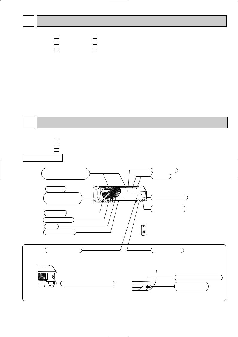
INDOOR UNIT
Air cleaning filter (white bellows type)
Panel
Catechin air filter (With deodorizer)
Air outlet
Vertical vanes
Fan
Horizontal vane
Operation section
(When the front panel is opened)
Emergency operation switch
Front panel
Air inlet

 to Breaker
Power supply cord
Remote control receiving section

 Remote controller
Display section
Operation indicator lamp
Remote control receiving section
3
MSC-A07YV- E1
MSC-A09YV- E1
MSC-A12YV- E1
ACCESSORIES
<Indoor unit>
1 |
Installation plate |
1 |
|
|
|
2 |
Installation plate fixing screw 4 o 25 mm |
5 |
|
|
|
3 |
Remote controller holder |
1 |
|
|
|
4 |
Fixing screw for 3 3.5 o 16 mm |
2 |
|
|
|
5 |
Battery (AAA) for remote controller |
2 |
|
|
|
6 |
Wireless remote controller |
1 |
|
|
|
7 |
Felt tape (Used for left or left-rear piping) |
1 |
|
|
|
8 |
Air cleaning filter |
1 |
|
|
|
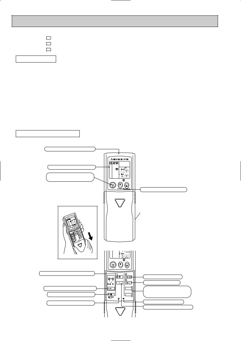
REMOTE CONTROLLER
Signal transmitting section
Operation display section
OPERATE /STOP (ON /OFF)button
|
|
PM |
|
|
AM |
ON/OFF |
TOO |
TOO |
|
WARM |
COOL |
TEMPERATURE buttons
Open the front lid. |
FAN SPEED CONTROL button
OPERATION SELECT button ECONO COOL button
RESET button
AM |
ON/OFF |
TOO |
TOO |
|
WARM |
COOL |
|
FAN |
STOP |
I FEEL COOL |
|
|
HEAT DRY |
VANE |
START |
|
|
|
/FAN |
|
|
/ |
|
HR. |
MODE |
|
|
ECONO COOL |
|
MIN. |
|
RESET CLOCK |
|
Indication of remote controller model is on back.
OFF-TIMER button ON-TIMER button
HR. button MIN. button (TIME SET button)
CLOCK SET button
VANE CONTROL button
4
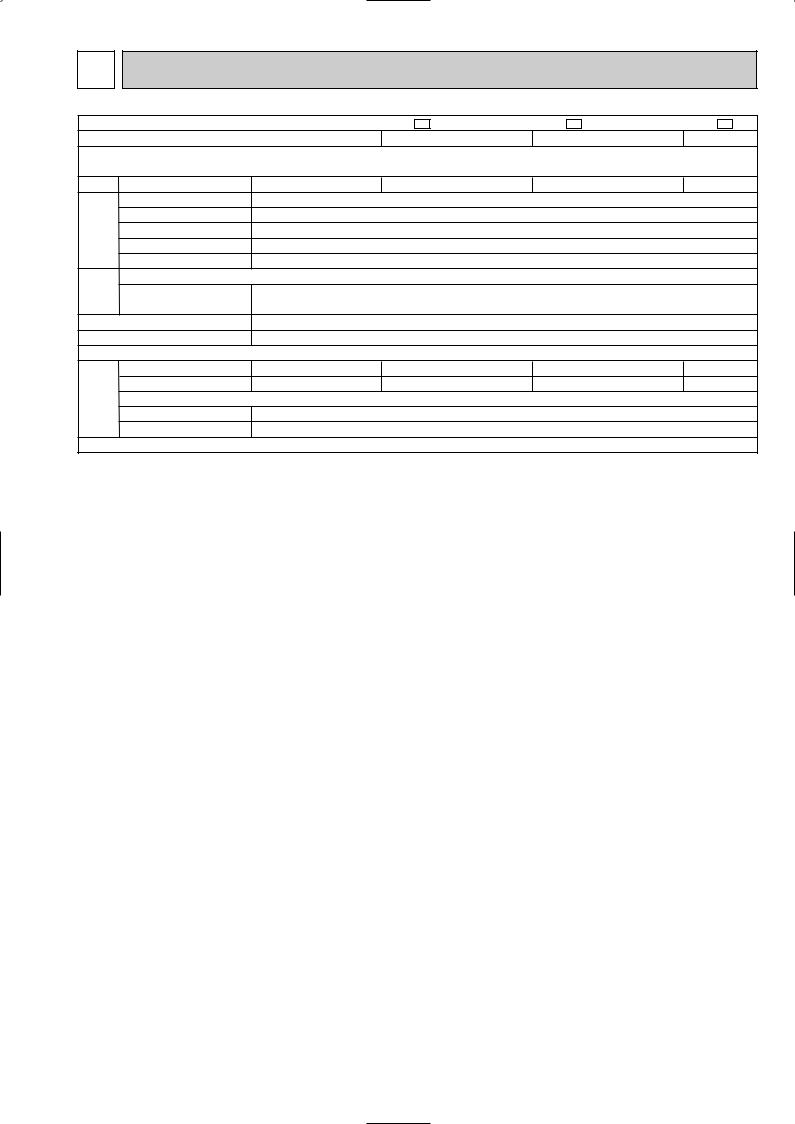
3 SPECIFICATION
Indoor model
Function
Indoor unit power supply
Capacity Air flow(High/Med.w/Loww)
Power outlet
Electrical |
data |
Running current |
|
|
|
||
|
|
Power input |
|
|
|
Power factor |
|
|
|
Fan motor current |
|
Fan |
motor |
Model |
|
Winding |
|||
|
|
||
|
|
resistance(at 20:) |
|
|
|
Dimensions WOHOD |
|
|
|
Weight |
|
|
|
Air direction |
|
|
remarks |
Sound level(High/Med.w/Loww) |
|
Special |
Fan speed(High/Med.w/Loww) |
||
Thermistor RT11(at 25:) |
|||
|
|
Fan speed regulator |
|
|
|
Thermistor RT12(at 25:) |
|
|
|
Remote controller model |
|
MSC-A07YV - E1 |
MSC-A09YV - E1 |
MSC-A12YV - E1 |
||||
|
Cooling |
Heating |
Cooling |
Heating |
Cooling |
Heating |
|
|
Single phase |
Single phase |
Single phase |
||||
|
230V,50Hz |
230V,50Hz |
230V,50Hz |
||||
K /h |
474/372w/276w 510/420w/342w |
474/384 w/306w 588/456w/342w |
582/444 w/324w 606/498w/396w |
||||
A |
|
10 |
10 |
|
|
10 |
|
A |
0.17 |
0.17 |
|
0.19 |
|||
W |
|
35 |
35 |
|
|
40 |
|
% |
|
90 |
90 |
|
|
92 |
|
A |
0.17 |
0.17 |
|
0.19 |
|||
|
RC4V19-LA |
RC4V19-LA |
RC4V19-KA |
||||
" |
WHT-BLK 413 |
WHT-BLK 413 |
WHT-BLK 316 |
||||
BLK-RED 334 |
BLK-RED 334 |
BLK-RED 299 |
|||||
|
|||||||
mm |
815O278O244 |
815O278O244 |
815O278O244 |
||||
kg |
|
9 |
9 |
|
|
10 |
|
|
|
5 |
5 |
|
|
5 |
|
dB |
36/31w/25 w |
36/31w/25 w |
36/31w/25w |
39/32w/25 w |
40/33w/26w |
39/33w/26w |
|
rpm |
900/750w/600w 950/820w/700w |
900/770w/650w 1,050/870w/700w |
930/760w/600w 960/830w/700w |
||||
|
|
3 |
3 |
|
|
3 |
|
k" |
|
10 |
10 |
|
|
10 |
|
k" |
|
10 |
10 |
|
|
10 |
|
|
KP1A or KG3A |
KP1A or KG3A |
KP1A or KG3A |
||||
NOTE: 1. Test conditions are based on ISO 5151. |
|
|
Cooling : Indoor |
DB27°C WB19°C |
Heating : Indoor DB20°C |
Outdoor DB35°C WB24°C |
|
OutdoorDB 7°C/WB 6°C |
Indoor-Outdoor piping length 5m
2.Remote controller model KP1A and KG3A are the same in terms of specification. W Reference value
5

4 NOISE CRITERIA CURVES
MSC-A07YV- |
E1 |
FAN SPEED FUNCTION |
SPL(dB(A)) |
LINE |
|||||
|
|
|
|
|
|||||
|
|
|
|
|
High |
|
COOL |
36 |
|
|
|
|
|
|
|
HEAT |
|
||
|
|
|
|
|
|
|
|
|
|
|
|
|
|
|
Test conditions, |
|
|
||
|
|
|
|
|
|
Cooling : DB27: |
WB19: |
||
|
90 |
|
|
|
|
Heating : DB20: |
WB -: |
||
|
|
|
|
|
|
|
|
|
|
MICRO BAR |
80 |
|
|
|
|
|
|
|
|
70 |
|
|
|
|
|
|
|
|
|
dB re 0.0002 |
|
|
|
|
|
|
|
|
|
|
|
|
|
|
|
|
|
NC-70 |
|
60 |
|
|
|
|
|
|
|
|
|
LEVEL, |
|
|
|
|
|
|
|
|
NC-60 |
|
|
|
|
|
|
|
|
|
|
PRESSURE |
50 |
|
|
|
|
|
|
|
|
|
|
|
|
|
|
|
|
NC-50 |
|
|
|
|
|
|
|
|
|
|
|
BAND SOUND |
40 |
|
|
|
|
|
|
|
|
|
|
|
|
|
|
|
|
NC-40 |
|
30 |
|
|
|
|
|
|
|
|
|
OCTAVE |
|
|
|
|
|
|
|
|
|
|
|
|
|
|
|
|
|
NC-30 |
|
|
|
|
|
|
|
|
|
|
|
|
20 |
APPROXIMATE |
|
|
|
|
|
|
|
|
|
TERESHOLD OF |
|
|
|
|
|
|
|
|
|
HEARING FOR |
|
|
|
|
|
NC-20 |
|
|
|
CONTINUOUS |
|
|
|
|
|
||
|
|
|
|
|
|
|
|
||
|
|
NOISE |
|
|
|
|
|
|
|
|
10 |
63 |
125 |
250 |
500 |
1000 |
2000 |
4000 |
8000 |
|
|
||||||||
BAND CENTER FREQUENCIES, Hz
MSC-A12YV- |
E1 |
FAN SPEED FUNCTION |
SPL(dB(A)) |
LINE |
|||||
|
|
|
|
|
|||||
|
|
|
|
|
High |
|
COOL |
40 |
|
|
|
|
|
|
|
HEAT |
39 |
|
|
|
|
|
|
|
|
|
|
||
|
|
|
|
|
Test conditions, |
|
|
||
|
90 |
|
|
|
|
Cooling : DB27: |
WB19: |
||
|
|
|
|
|
|
|
|
|
|
MICRO BAR |
80 |
|
|
|
|
|
|
|
|
70 |
|
|
|
|
|
|
|
|
|
dB re 0.0002 |
|
|
|
|
|
|
|
|
|
|
|
|
|
|
|
|
|
NC-70 |
|
60 |
|
|
|
|
|
|
|
|
|
LEVEL, |
|
|
|
|
|
|
|
|
NC-60 |
|
|
|
|
|
|
|
|
|
|
PRESSURE |
50 |
|
|
|
|
|
|
|
|
|
|
|
|
|
|
|
|
NC-50 |
|
|
|
|
|
|
|
|
|
|
|
BAND SOUND |
40 |
|
|
|
|
|
|
|
|
|
|
|
|
|
|
|
|
NC-40 |
|
30 |
|
|
|
|
|
|
|
|
|
OCTAVE |
|
|
|
|
|
|
|
|
|
|
|
|
|
|
|
|
|
NC-30 |
|
|
|
|
|
|
|
|
|
|
|
|
20 |
APPROXIMATE |
|
|
|
|
|
|
|
|
|
TERESHOLD OF |
|
|
|
|
|
|
|
|
|
HEARING FOR |
|
|
|
|
|
NC-20 |
|
|
|
CONTINUOUS |
|
|
|
|
|
||
|
|
|
|
|
|
|
|
||
|
|
NOISE |
|
|
|
|
|
|
|
|
10 |
63 |
125 |
250 |
500 |
1000 |
2000 |
4000 |
8000 |
|
|
||||||||
BAND CENTER FREQUENCIES, Hz
MSC-A09YV- |
E1 |
FAN SPEED FUNCTION |
SPL(dB(A)) |
LINE |
|||||
|
|
COOL |
36 |
|
|||||
|
|
|
|
|
High |
|
HEAT |
39 |
|
|
|
|
|
|
|
|
|
||
|
|
|
|
|
Test conditions. |
|
|
||
|
|
|
|
|
|
Cooling : DB27: |
WB19: |
||
|
90 |
|
|
|
|
Heating : DB20: |
WB -: |
||
|
|
|
|
|
|
|
|
|
|
MICRO BAR |
80 |
|
|
|
|
|
|
|
|
70 |
|
|
|
|
|
|
|
|
|
dB re 0.0002 |
|
|
|
|
|
|
|
|
|
|
|
|
|
|
|
|
|
NC-70 |
|
60 |
|
|
|
|
|
|
|
|
|
LEVEL, |
|
|
|
|
|
|
|
|
NC-60 |
|
|
|
|
|
|
|
|
|
|
PRESSURE |
50 |
|
|
|
|
|
|
|
|
|
|
|
|
|
|
|
|
NC-50 |
|
|
|
|
|
|
|
|
|
|
|
BAND SOUND |
40 |
|
|
|
|
|
|
|
|
|
|
|
|
|
|
|
|
NC-40 |
|
30 |
|
|
|
|
|
|
|
|
|
OCTAVE |
|
|
|
|
|
|
|
|
|
|
|
|
|
|
|
|
|
NC-30 |
|
|
|
|
|
|
|
|
|
|
|
|
20 |
APPROXIMATE |
|
|
|
|
|
|
|
|
|
TERESHOLD OF |
|
|
|
|
|
|
|
|
|
HEARING FOR |
|
|
|
|
|
NC-20 |
|
|
|
CONTINUOUS |
|
|
|
|
|
||
|
|
|
|
|
|
|
|
||
|
|
NOISE |
|
|
|
|
|
|
|
|
10 |
63 |
125 |
250 |
500 |
1000 |
2000 |
4000 |
8000 |
|
|
||||||||
BAND CENTER FREQUENCIES, Hz
INDOORUNIT
WALL
1m
0.8m
MICROPHONE
6
5 
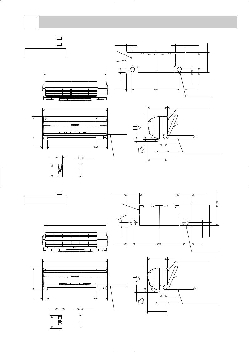
 OUTLINES AND DIMENSIONS
MSC-A07YV - E1 |
81.5 |
MSC-A09YV - E1 |
|
INDOOR UNIT |
Installation plate |
|
Indoor unit |
|
783 |
133.5
231.5
Unit: mm
271 4.5
41 |
|
|
2.5 |
42 |
81.5 |
326 |
326 |
81.5 |
|
Wall hole [65
815
278
60 |
606 |
58 |
19 |
162 |
|
Wireless remote controller
|
Air in |
more |
|
7 or |
|
|
|
|
149 |
|
30 |
|
|
Air out
Power supply cord Lead to right 1.0m Lead to left 0.3m
2425 Installation plate
{Liquid line [6.35-0.5m Gas line [9.52-0.43m Insulation [37 O.D
[21 I.D
|
90 |
Drain hose [16 |
|
110 |
|
|
(Connected part O,D) |
|
|
|
|
244 |
|
Insulation [28 |
|
|
MSC-A12YV - E1 |
161.5 |
INDOOR UNIT |
Installation plate |
|
|
|
Indoor unit |
|
783 |
161.5
17.5
218.5 |
258 |
278
|
|
41 |
|
|
|
|
2.5 |
42 |
|
|
81.5 |
326 |
|
326 |
|
81.5 |
|
|
|
|
|
|
|
|
Wall hole [65 |
|
|
815 |
|
|
242 |
5 |
Installation plate |
||
|
|
|
more |
|
|
|
Liquid line [6.35-0.5m |
|
|
|
|
|
|
|
Gas line [9.52-0.43m |
||
|
|
Air in |
or |
|
|
{ Insulation [37 O.D |
||
|
|
|
|
|
|
[21 I.D |
||
|
|
|
7 |
|
|
|
||
|
|
|
|
|
|
|
|
|
60 |
606 |
149 |
30 |
|
90 |
|
Drain hose [16 |
|
|
110 |
|||||||
|
|
|
|
|||||
|
|
|
|
|
(Connected part O,D) |
|||
58 |
19 |
|
|
|
|
|
||
|
Air out |
244 |
|
|
Insulation [28 |
|||
|
|
Power supply cord |
|
|
|
|
|
|
|
|
|
|
|
|
|
|
|
|
|
Lead to right 1.0m |
|
|
|
|
|
|
162 |
|
Lead to left 0.3m |
|
|
|
|
|
|
|
|
|
|
|
|
|
|
|
Wireless remote controller
7
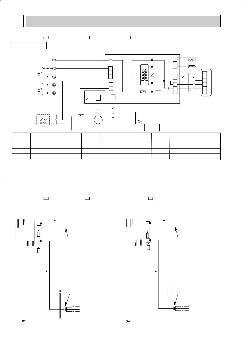
6 |
WIRING DIAGRAM |
|
|
|
|
|
|
|
|
|
|
||||
MSC-A07YV - E1 |
MSC-A09YV - E1 |
MSC-A12YV - E1 |
|
|
|
|
|
|
|
|
|||||
INDOOR UNIT |
|
|
MODELS WIRING DIAGRAM |
|
|
|
|
|
|
|
|||||
|
TO OUTDOOR |
TB |
|
|
|
|
|
|
|
|
|
|
|
|
|
|
UNIT |
BRN |
|
|
|
TAB12 |
|
|
|
CN |
|
RT12 |
|
||
|
CONNECTING |
L |
|
|
|
|
|
|
|
|
|||||
|
BRN |
|
|
|
|
|
|
|
|
112 |
|
|
|
|
|
|
FOR |
|
|
|
|
CN201 |
|
|
|
CN |
|
RT11 |
|
||
|
3 |
RED |
|
|
|
|
|
|
|
|
|||||
|
MUH OR |
|
|
|
T11 |
|
|
111 |
|
|
|||||
|
|
|
|
3 |
|
|
|
|
|||||||
|
MXZ TYPE |
|
|
|
|
|
|
|
|
|
|
|
|
|
|
|
N |
|
|
|
|
2 |
|
|
|
|
|
BLK |
1 |
|
|
|
12V |
BLU |
|
|
|
|
NR11 |
|
|
3 |
|
||||
|
|
|
|
|
|
CN |
GRY |
|
|||||||
|
|
|
|
1 |
|
|
2 |
|
|||||||
|
FOR |
BLU |
|
|
|
|
|
|
|
121 |
|
YLW |
|
||
|
|
|
|
|
CN202 |
|
|
|
|
3 |
|
||||
|
|
|
|
|
|
|
|
|
|
MF |
|||||
|
MU OR |
2 |
WHT |
|
|
|
|
C11 |
1 |
|
BRN |
||||
|
MUX TYPE |
|
|
|
|
|
2 |
|
|
WHT |
4 |
|
|||
|
1 |
|
|
|
|
1 |
F11 |
SR141 |
|
3 |
|
5 |
|
||
|
12V |
BLK |
|
|
|
|
|
|
|
5 |
|
RED |
6 |
|
|
|
|
|
|
|
|
|
|
|
|
|
|||||
|
POWER |
|
|
|
CN |
|
CN |
|
|
CN211 |
|
|
|
|
|
|
|
|
LD103 |
151 |
|
101 |
|
|
|
|
|
|
|
|
|
|
SUPPLY |
|
|
|
|
|
ELECTRONIC CONTROL P.C. BOARD |
|
|
|
|
||||
|
CORD |
|
|
|
|
|
|
|
|
|
|
|
|
|
|
|
~/N 230V |
|
GRN |
|
|
5 |
5 |
|
|
|
|
|
|
|
|
|
50Hz |
|
|
|
POWER MONITOR, |
|
|
|
|
|
|
|
|
||
|
PE |
|
|
|
|
|
|
|
|
|
|
|
|
|
|
|
|
GRN/YLW |
|
MV |
|
RECEIVER |
|
|
|
|
|
|
|
|
|
|
|
|
|
|
|
|
|
|
|
|
|
|
|||
|
|
|
|
|
P.C.BOARD |
|
|
|
|
|
|
|
|
||
|
|
|
|
|
|
|
|
|
|
|
|
|
|
||
|
CIRCUIT BREAKER |
|
|
|
|
REMOTE |
|
|
|
|
|
|
|||
|
|
|
|
|
CONTROLLER |
|
|
|
|
|
|
||||
|
|
|
|
|
|
|
|
|
|
|
|
||||
|
|
|
|
|
|
|
|
|
|
|
|
|
|
||
SYMBOL |
NAME |
|
SYMBOL |
|
NAME |
|
SYMBOL |
|
|
|
NAME |
|
|
||
C11 |
INDOOR FAN CAPACITOR |
NR11 |
VARISTOR |
|
TB |
|
TERMINAL BLOCK |
|
|
||||||
F11 |
FUSE(3.15A) |
|
RT11 |
ROOM TEMPERATURE THERMISTOR |
T11 |
|
TRANSFORMER |
|
|
||||||
MF |
INDOOR FAN MOTOR (INNER FUSE) |
RT12 |
INDOOR COIL THERMISTOR |
MV |
VANE MOTOR |
SR141 |
SOLID STATE RELAY |
NOTE:1. About the outdoor side electric wiring refer to the outdoor unit electric wiring diagram for servicing.
2.Use copper conductors only. (For field wiring)
3.Symbols below indicate.
/: Terminal block,  : Connector
7 |
|
|
REFRIGERANT SYSTEM DIAGRAM |
|
|
|
|
|
|
|
|
|
|
|
|
|
|
|
|
|
|
|
|
|||||||||||||||||||||||||||||||||
|
|
|
|
|
|
|
|
|
|
|
|
|
|
|
|
|
|
|
|
|
|
|
|
|
|
|
|
|
|
|
|
|
|
|
|
|
|
|
|
|
|
|
|
|
|
|
|
|
|
|
|
|
|
|
|
|
MSC-A07YV - E1 |
MSC-A09YV - E1 |
MSC-A12YV - E1 |
|
|
|
|
|
|
|
|
|
|
|
|
|
|
|
|
|
|
|
Unit:mm |
||||||||||||||||||||||||||||||||||
|
|
|
|
|
|
|
Refrigerant pipe [9.52 |
|
|
|
|
|
|
|
|
|
|
Refrigerant pipe [12.7 |
||||||||||||||||||||||||||||||||||||||
|
INDOOR UNIT |
|
|
INDOOR UNIT |
|
|||||||||||||||||||||||||||||||||||||||||||||||||||
|
|
|
|
|
|
|
|
|
|
|
|
|
|
|
(with heat insulator) |
|
|
|
|
|
|
|
|
|
|
(with heat insulator) |
||||||||||||||||||||||||||||||
|
|
|
|
|
|
|
|
|
|
|
|
|
|
|
|
|
|
|
|
|
|
|||||||||||||||||||||||||||||||||||
|
|
|
|
|
|
|
|
|
|
|
|
|
|
|
|
|
|
|
|
|
|
|
|
|
|
|
|
|
|
|
|
|
|
|
|
|
|
|
|
|
|
|
|
|
|
|
|
|
|
|
|
|
|
|
||
|
|
|
|
|
|
|
|
|
|
|
|
|
|
|
|
|
|
|
|
|
|
|
|
|
|
|
|
|
|
|
|
|
|
|
|
|
|
|
|
|
|
|
|
|
|
|
|
|
|
|
|
|
|
|
|
|
|
|
|
|
|
|
|
|
|
Indoor coil |
|
|
|
|
|
|
|
|
|
|
|
|
|
|
|
|
|
|
Indoor |
|
Indoor coil |
|
|
|
|
|
|
|
|
|
|
|
|
|
|
|
|
||||||||||
|
|
Indoor |
|
|
|
|
|
|
|
|
|
|
|
|
|
|
|
|
|
|
|
|
|
|
|
|
|
|
|
|
|
|
|
|
|
|
|
|
|
|||||||||||||||||
|
|
|
|
|
|
thermistor |
|
|
|
|
|
|
|
|
|
|
|
|
|
|
|
|
|
|
heat |
|
thermistor |
|
|
|
|
|
|
|
|
|
|
|
|
|
|
|
|
|||||||||||||
|
|
heat |
|
|
|
|
|
|
|
|
|
|||||||||||||||||||||||||||||||||||||||||||||
|
|
|
|
|
|
RT12 |
|
|
|
|
|
|
|
|
|
|
|
|
|
|
|
|
|
|
|
|
exchanger |
|
|
|
|
RT12 |
|
|
|
|
|
|
|
|
|
|
|
|
|
|
|
|
||||||||
|
|
exchanger |
|
|
|
|
|
|
|
|
Flared connection |
|
|
|
|
|
|
|
||||||||||||||||||||||||||||||||||||||
|
|
|
|
|
|
|
|
|
|
|
|
|
|
|
|
|
|
|
|
|
|
|
|
|
|
|
Flared connection |
|||||||||||||||||||||||||||||
|
|
|
|
|
|
|
|
|
|
|
|
|
|
|
|
|
|
|
|
|
|
|
|
|
|
|
|
|
|
|
|
|
|
|
|
|
|
|
|
|
|
|
|
|
|
|
|
|
|
|
|
|
|
|
|
|
|
|
|
|
|
|
|
|
|
|
|
|
|
|
|
|
|
|
|
|
|
|
|
|
|
|
|
|
|
|
|
|
|
|
|
|
|
|
|
|
|
|
|
|
|
|
|
|
|
|
|
|
|
|
|
|
|
|
Room temperature |
|
|
|
|
|
|
|
|
|
|
|
|
|
|
|
|
|
|
|
Room temperature |
|
|
|
|
|
|
|
|
|
|
|
|
|
|
|
|
|
|
|
|
|||||||||||||||
|
|
|
|
|
|
|
|
|
|
|
|
|
|
|
|
|
|
|
|
thermistor |
|
|
|
|
|
|
|
|
|
|
|
|
|
|
|
|
|
|
|
|
|
|
||||||||||||||
|
thermistor |
|
|
|
|
|
|
|
|
|
|
|
|
|
|
|
|
|
|
|
|
|
|
|
|
|
|
|
|
|
|
|
|
|
|
|
|
|
|
|
|
|
|
|
|
|
|
|
|
|
||||||
|
|
|
|
|
|
|
|
|
|
|
|
|
|
|
|
|
|
|
|
|
|
|
|
|
|
|
|
RT11 |
|
|
|
|
|
|
|
|
|
|
|
|
|
|
|
|
|
|
|
|
|
|
||||||
|
RT11 |
|
|
|
|
|
|
|
|
|
|
|
|
|
|
|
|
|
|
|
|
|
|
|
|
|
|
|
|
|
|
|
|
|
|
|
|
|
|
|
|
|
|
|
|
|
|
|
|
|
||||||
|
|
|
|
|
|
|
|
|
|
|
|
|
|
|
|
|
|
|
|
|
|
|
|
|
|
|
|
|
|
|
|
|
|
|
|
|
|
|
|
|
|
|
|
|
|
|
|
|
|
|
|
|
||||
|
|
|
|
|
|
|
|
|
|
|
|
|
|
|
|
|
|
|
|
|
|
|
|
|
|
|
|
|
|
|
|
|
|
|
|
|
|
|
|
|
|
|
|
|
|
|
|
|
|
|
|
|
|
|
|
|
|
|
|
|
|
|
|
|
|
|
|
|
|
|
|
|
|
|
|
|
|
|
|
|
|
|
|
|
|
|
|
|
|
|
|
|
|
|
|
|
|
|
|
|
|
|
|
|
|
|
|
|
|
|
|
|
|
|
|
|
|
|
|
|
|
|
|
|
|
|
|
|
|
|
|
|
|
|
|
|
|
|
|
|
|
|
|
|
|
|
|
|
|
|
|
|
|
|
|
|
|
|
|
|
|
|
|
|
|
|
|
|
|
|
|
|
|
|
|
|
|
|
|
|
|
|
|
|
|
|
|
|
|
|
|
|
|
|
|
|
|
|
|
|
|
|
|
|
|
|
|
|
|
|
|
|
|
|
|
|
|
|
|
|
|
|
|
|
|
|
|
Flared connection |
Flared connection |
Refrigerant flow |
Refrigerant pipe [6.35 |
|
|
Refrigerant flow |
Refrigerant pipe [6.35 |
|
|
||||
in cooling |
(with heat insulator) |
|
|
in cooling |
(with heat insulator) |
|
|
8 |
|
|
|
8 
 MICROPROCESSOR CONTROL
MSC-A07YV - E1
MSC-A09YV - E1
MSC-A12YV - E1
Once the operation mode are set, the same operation mode can be repeated by simply turning the OPERATE/STOP (ON/OFF) button ON. Indoor unit receives the signal with a beep tone.
When the system turns off, 3-minute time delay will operate to protect system from overload and compressor will not restart for 3 minutes.
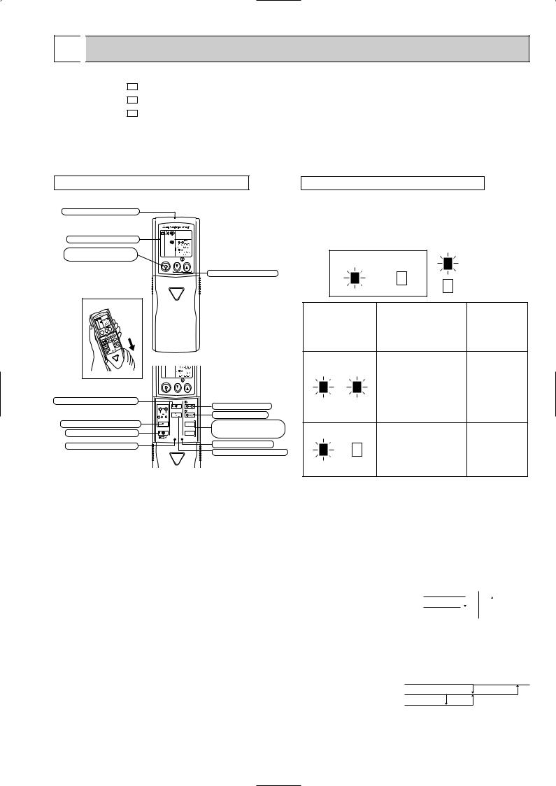
WIRELESS REMOTE CONTROLLER |
INDOOR UNIT DISPLAY SECTION |
Signal transmitting section
Operation Indicator lamp
The operation indicator at the right side of the indoor unit indicates the operation state.
Operation display section |
|
|
PM |
OPERATE /STOP |
|
|
AM |
|
|
|
|
(ON /OFF)button |
ON/OFF |
TOO |
TOO |
|
|
WARM |
COOL |
TEMPERATURE buttons
Open the front lid. |
AM |
ON/OFF TOO  TOO WARM COOL
FAN SPEED CONTROL button |
FAN |
STOP |
OFF-TIMER button |
I FEEL COOL |
|
||
HEAT |
VANE |
START |
ON-TIMER button |
DRY |
|
||
/ |
|
||
/FAN |
|
|
|
MODE |
HR. |
HR. button |
|
OPERATION SELECT button |
|
|
|
ECONO COOL |
MIN. |
MIN. button |
|
ECONO COOL button |
RESET CLOCK |
|
(TIME SET button) |
RESET button |
|
|
CLOCK SET button |
|
|
|
VANE CONTROL button |
8-1. COOL ( 
 ) OPERATION
•The following indication does not depend on the shape of lamp.
Operation Indicator
lighted
not lighted
Difference between target
Indication Operation state temperature and room temperature
This shows that the air conditioner is operating to reach
the target temperature.
Approx. 2 :
Please wait until the target temperature is obtained.
or more
This shows that the |
|
room temperature is |
Approx. 2 : |
approaching the |
or less |
target temperature. |
|
(1)Press OPERATE/STOP(ON/OFF) button. OPERATION INDICATOR lamp of the indoor unit turns on with a beep tone.
(2)Select COOL mode with the OPERATION SELECT button.
(3)Press TEMPERATURE buttons (TOO WARM or TOO COOL button)to select the desired temperature. The setting range is 16 ~ 31°C
|
|
Difference between room |
||||||
1. Thermostat control |
|
temperature and set tem- |
||||||
|
perature during operation |
|||||||
Thermostat is ON or OFF by difference between room temperature and set temperature |
||||||||
|
|
|
|
|
|
|||
Initial temperature difference |
Thermostat |
Set temperature |
||||||
Room temperature minus set temperature : 0.3 : or more················································ON |
|
|||||||
|
|
|
|
|
|
|||
|
|
|
|
|
|
|||
Room temperature minus set temperature : less than -0.3 :············································OFF |
|
|
|
|
|
|
||
|
|
|
|
|
|
|||
|
|
|
|
|
|
|||
2.Indoor fan speed control
Indoor fan operates continuously at the set speed by FAN SPEED CONTROL button regardless of thermostat’s OFF-ON.
In Auto the fan speed is as follows.
Initial temperature difference
Room temperature minus set temperature : 1.7 degrees or more·······························High Room temperature minus set temperature : Between 1 and 1.7 degrees···················Med. Room temperature minus set temperature : less than 1 degree··································Low
-0.3 : 0.3 :
Difference between room temperature and set temperature during operation
3 deg.
1 deg. 1.7 deg.
9
3. Coil frost prevention
Temperature control
When the indoor coil thermistor RT12 reads 4°C or below(MSC-A07/A09YV) / 0°C or below(MSC-A12YV) for 5 minutes, the coil frost prevention mode starts.
The indoor fan operates at the set speed and the compressor stops for 5 minutes.
After that, if RT12 still reads below 4°C (MSC-A07/A09YV) / 0°C (MSC-A12YV), this mode is prolonged until the RT12 reads over 4°C (MSC-A07/A09YV) / 0°C (MSC-A12YV).
Time control
When the three conditions as follows have been satisfied for 1 hour and 45 minutes, the compressor stops for 3 minutes. The indoor fan operates at the set speed.
a.Compressor has been continuously operating.
b.Indoor fan speed is Low or Med.
c.Room temperature is below 26°C.
When compressor stops, the accumulated time is cancelled. When compressor restarts, time counting starts from the beginning.
Time counting also stops temporarily when the indoor fan speed becomes High or the room temperature exceeds 26°C. However, when two of the above conditions (b.and c.) are satisfied again, time accumulation is resumed.
Operation chart |
|
|
|
|
|
Example |
|
ON |
|
ON |
|
|
|
|
|||
|
|
|
OFF |
|
|
Compressor |
OFF |
|
|
|
|
Outdoor fan |
|
|
|
|
|
ON ( continuously at set speed) |
|
|
|||
Indoor fan |
|
|
|||
|
|
|
|
|
|
8-2. DRY (  ) OPERATION
(1)Press OPERATE/STOP(ON/OFF) button.
OPERATION INDICATOR lamp of the indoor unit turns on with a beep tone.
(2)Select DRY mode with the OPERATION SELECT button.
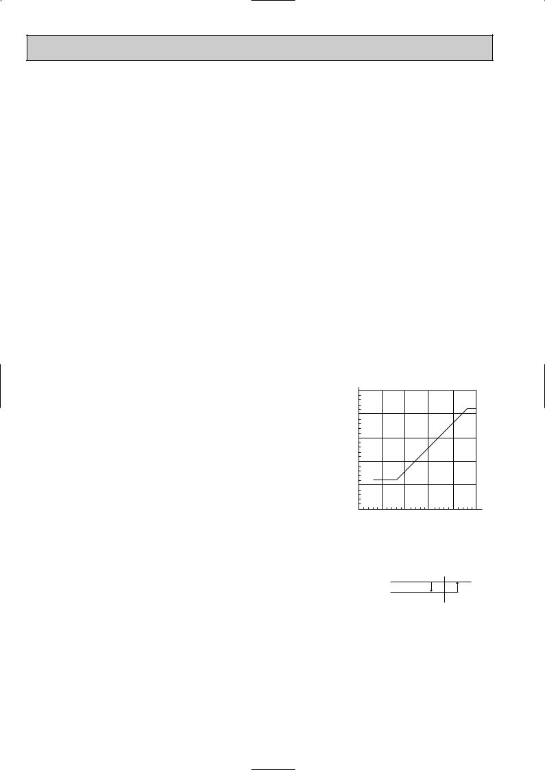
(3)The microprocessor reads the room temperature and determines the set temperature. Set temperature is as shown on the right chart.
DRY operation will not function when the room temperature is 13°C or below.
(4)When DRY operation functions the fan speed is lower than COOL operation except at (fan speed) Low.
The system for dry operation uses the same refrigerant circuit as the cooling circuit.
The compressor and the indoor fan are controlled by the room temperature.
|
Set temperature and |
|
|
|||
|
35: initial room temperature in dry mode |
|||||
|
30 |
|
|
|
|
|
temperature |
25 |
|
|
|
|
|
20 |
|
|
|
|
|
|
Set |
|
|
|
|
|
|
|
|
|
|
|
|
|
|
15 |
|
|
|
|
|
|
10 |
|
|
|
|
35 : |
|
10 |
15 |
20 |
25 |
30 |
|
Initial room temperature
1.Thermostat control
Thermostat is ON or OFF by difference between room temperature and set temperature.
Initial temperature difference Thermostat Room temperature minus set temperature : 0.3 : or more················································ON Room temperature minus set temperature : less than -0.3 :············································OFF
2.Indoor fan speed control
Indoor fan operates at the set speed by FAN SPEED CONTROL button. In Auto fan speed becomes Low.
3.The operation of the compressor and indoor / outdoor fan <MU-A07/A09/A12YV, MUH-A07/A09/A12YV, MUX-A10/A19/A20/A22/A25/A26WV>
Compressor operates by room temperature control and time control. Indoor fan and outdoor fan operate in the same cycle as the compressor.
When the room temperature is 23°C or over:
When the thermostat is ON, the compressor repeats 8 minutes ON and 3 minutes OFF. When the thermostat is OFF, the compressor repeats 4 minutes OFF and 1 minute ON.
When the room temperature is under 23°C.
When the thermostat is ON, the compressor repeats 2 minutes ON and 3 minutes OFF. When the thermostat is OFF, the compressor repeats 4 minutes OFF and 1 minute ON.
Set temperature
-0.3 : 0.3 :
10
 Loading...