


Revision:
●PARTS LIST have been partially modified. ●Please void OB311.
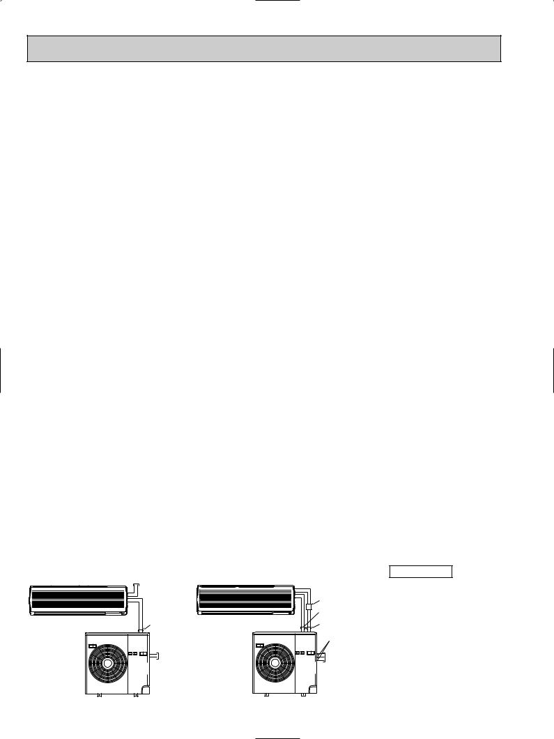
SPLIT-TYPE, AIR CONDITIONERS
No. OB311
REVISED EDITION-A
SERVICE MANUAL
Wireless type
Models
MS24WN (W) · MU24WN
CONTENTS
1. FEATURES ······················
2.PART NAMES AND FUNCTIONS·············
3.SPECIFICATION····················
|
4. DATA························· |
|
INDOOR UNIT |
5. OUTLINES AND DIMENSIONS ············· |
|
6. WIRING DIAGRAM ··················· |
||
Indication of model name |
7. REFRIGERANT SYSTEM DIAGRAM ··········· |
|
MS24WN |
||
8. MICROPROCESSOR CONTROL ············· |
||
|
||
Remote |
9. SERVICE FUNCTIONS ················· |
|
controller |
10. TROUBLESHOOTING·················· |
|
|
||
|
11. DISASSEMBLY INSTRUCTIONS············· |
|
|
12. PARTS LIST······················ |
|
OUTDOOR UNIT |
13. OPTIONAL PARTS ··················· |
Indication of model name
MU24WN
The Slim Line.


 From Mitsubishi Electric.
TM
C
L
US
ISTED

Revision:
•Parts No. has been changed due to the color change of outdoor unit parts. WHITE NEW WHITE (Brighter)
•Capillary tube has been added to parts list.
Model |
Page |
Part name |
Part number |
|
|
|
|
|
|
MU24WN |
47 |
CAPILLARY TUBE (TAPER PIPE) |
E02 784 936 |
|
[0.14X[0.09X1-31/32 |
||||
|
|
|

1 FEATURES
MS24WN
|
|
MU24WN |
|
LCD wireless |
|
|
remote controller |
|
Model |
Cooling capacity |
SEER |
MS24WN |
22,800 Btu/h |
10.5 |
“I FEEL CONTROL” IN OUR LCD WIRELESS REMOTE CONTROLLER WITH ON/OFF PROGRAM TIMER
Mitsubishi Electric’s new wireless remote controller incorporates a number of advanced features that provide even greater control and ease-to-use. It has a liquid crystal display which indicates such information as mode, fan speed and temperature selected as well as the programmed ON/OFF timer. It is also equipped with “I Feel Control”, a unique Mitsubishi Electric feature that allows the user to adjust the temperature to exactly the level he or she wants simply by tapping the button that describes present conditions : “Too Cool” or “Too Warm”. The optimum temperature set this way is then memorized for immediate recall whenever the air conditioner is used again.
Select desired air flow direction. REMOTE-CONTROL OPERATION MODE
Using the remote controller, you can select from five airflow settings to match room layout and the location of people. Also, you
can set the vane to swing automatically.
SWING
SWING
AUTO-RESTART FUNCTION
The auto restart function restarts the equipment automatically when power is restored following an outage. Operation resumes in the mode in which the equipment was running just before the outage.
HIGH PERFORMANCE ROTARY COMPRESSOR
The advanced design of Mitsubishi Electric’s powerful and energy efficient rotary compressor results in lower operating costs and longer service life.
3

2 |
PART NAMES AND FUNCTIONS |
|
INDOOR UNIT |
|
|
MS24WN |
|
|
|
|
Grille |
|
Deodorizing filter (option) |
Air inlet |
|
(Gray sponge type) |
|
|
Air cleaning filter (option) |
|
|
(White bellows type) |
|
|
Front panel |
Remote control |
|
|
receiving section |
|
Air filter |
Horizontal vane |
|
|
Remote controller |
|
Vertical vane |
|
|
Operation section |
Display section |
(When the grille is opened) |
|
|
|
|
Operation indicator lamp |
|
|
Operation Indicator |
|
Emergency operation switch |
Receiving section |
|
|
|
ACCESSORIES
|
|
MS24WN |
|
|
|
1 |
Installation plate |
1 |
2 |
Installation plate fixing screw 4 x 25 mm(0.16 x 0.98 in.) |
7 |
3 |
Remote controller holder |
1 |
4 |
Fixing screw for 3 3.5 x 16 mm(0.14 x 0.63 in.) (Black) |
2 |
5 |
Battery (AAA) for remote controller |
2 |
6 |
Wireless remote controller |
1 |
7 |
Felt tape (Used for left or left-rear piping) |
1 |
OUTDOOR UNIT
MU24WN
4
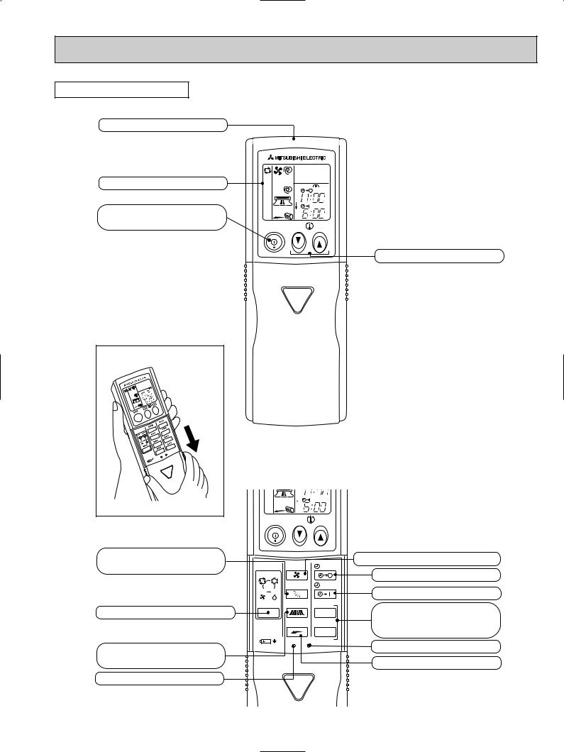
REMOTE CONTROLLER
MS24WN
Signal transmitting section
Operation display section
OPERATE/ STOP
(ON/ OFF)button
|
|
PM |
|
|
AM |
ON/OFF |
TOO |
TOO |
|
WARM |
COOL |
TEMPERATURE buttons
Open the front lid. |
VANE button (Horizontal vane button)
OPERATION SELECT button
WIDE VANE button (Vertical vane button)
RESET button
AM |
ON/OFF |
TOO |
TOO |
|
WARM |
COOL |
FAN |
STOP |
I FEEL COOL |
|
VANE |
START |
FAN DRY |
|
MODE WIDE VANE |
HR. |
LONG |
MIN. |
RESET CLOCK |
|
FAN SPEED CONTROL button
OFF-TIMER button
ON-TIMER button
HR. button MIN. button (TIME SET button)
CLOCK SET button
LONG button
5

3 |
|
|
SPECIFICATION |
|
|
||
|
|
|
|
|
|
|
|
|
|
|
|
|
|
|
|
Item |
|
|
Model |
MS24WN |
|||
|
|
|
|||||
Cooling capacity |
1 |
Btu/h |
22,800 |
||||
|
|||||||
Power consumption |
1 |
W |
2,170 |
||||
EER 1 [SEER] 2 |
|
|
10.5 (10.5) |
||||
INDOOR UNIT MODEL |
|
MS24WN |
|||||
External finish |
|
|
White |
||||
Power supply |
|
|
115V 60Hz 1[ |
||||
Max. fuse size (time delay)/ Disconnect switch |
A |
15 |
|||||
Min. ampacity |
|
A |
1.1 |
||||
Fan motor |
|
FAN Dry |
F.L.A |
0.82 |
|||
Airflow Low—Med.—High |
CFM |
431-491-565 |
|||||
COOL Dry(Wet) |
CFM |
402(346)-484(417)-565(487) |
|||||
|
|
|
|
||||
Moisture removal |
|
pt./h |
7.6 |
||||
Sound level Low-Med.-High |
dB(A) |
39-43-47 |
|||||
Cond. drain connection O.D. |
in. |
5/8 |
|||||
|
|
|
|
W |
in. |
43-5/16 |
|
Dimensions |
D |
in. |
8-15/16 |
||||
Weight |
|
H |
in. |
12-13/16 |
|||
|
|
lb. |
40 |
||||
OUTDOOR UNIT MODEL |
|
MU24WN |
|||||
External finish |
|
|
Munsell 5Y7/1 |
||||
Power supply |
|
|
208/230V 60Hz 1[ 3 wires |
||||
Max. fuse size (time delay) |
A |
25 |
|||||
Min. ampacity |
|
A |
22 |
||||
Fan motor |
|
Model |
F.L.A |
0.87 |
|||
|
|
|
|
|
PH33NPBT |
||
Compressor |
Winding resistance (at 68˚F) Ω |
C-R 0.84 C-S 2.09 |
|||||
|
R.L.A |
16 |
|||||
|
|
|
|
|
|||
|
|
|
|
|
L.R.A |
58 |
|
Refrigerant control |
|
|
Linear expansion valve |
||||
Sound level |
W |
dB(A) |
55 |
||||
|
|
|
|
in. |
34-1/4 |
||
Dimensions |
D |
in. |
11-5/8 |
||||
Weight |
|
H |
in. |
33-1/2 |
|||
|
|
lb. |
152 |
||||
REMOTE CONTROLLER |
|
Wireless type |
|||||
Control voltage (by built-in transformer) |
|
12V DC |
|||||
REFRIGERANT PIPING |
|
Not supplied (optional parts) |
|||||
Pipe size |
|
Liquid |
in. |
3/8 (0.0285) |
|||
(Min. wall thickness) |
Gas |
in. |
5/8 (0.0315) |
||||
Connection method |
Indoor |
|
Flared |
||||
Outdoor |
|
Flared |
|||||
|
|
|
|
|
|||
Between the indoor |
Height difference |
ft. |
Max. 25 |
||||
& outdoor units |
Piping length |
ft. |
Max. 50 |
||||
Refrigerant charge (R22) |
|
4 Ib. 5 oz. |
|||||
Refrigerant oil (Model) |
|
oz. |
27.9 (MS32N1) |
||||
Notes : Test conditions are based on ARI 210/240
1 : Rating conditions (cooling) — Indoor : 80˚FDB, 67˚FWB, Outdoor : 95˚FDB, (75˚FWB)2 : Rating conditions (cooling) — Indoor : 80˚FDB, 67˚FWB, Outdoor : 82˚FDB, 65˚FWB
Operating Range
|
|
Indoor intake air temperature |
Outdoor intake air temperature |
|
Cooling |
Maximum |
95˚FDB, 71˚FWB |
115˚FDB |
|
Minimum |
67˚FDB, 57˚FWB |
67˚FDB |
||
|
6
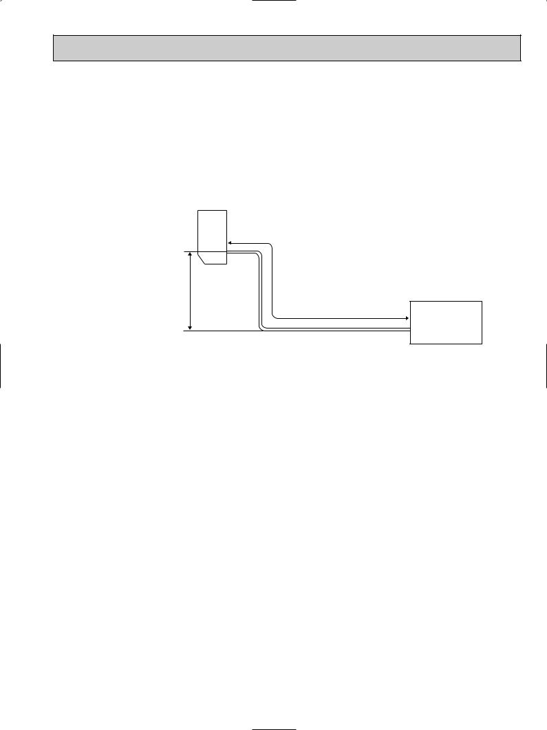
MAX. REFRIGERANT PIPING LENGTH & MAX. HEIGHT DIFFERENCE
|
|
Additional piping |
|
Piping size : in. |
|
Length of connecting pipe : in. |
|||
|
|
|
|
|
|
|
|
||
|
|
Gas |
Liquid |
|
|
||||
|
|
Max. length : ft. |
|
|
|||||
Model |
|
|
|
|
|
|
|||
Outside |
Minimum |
Outside |
Minimum |
Indoor unit |
Outdoor unit |
||||
A |
|||||||||
|
|
||||||||
|
|
|
diameter |
Wall |
diameter |
Wall |
|
|
|
|
|
|
thickness |
thickness |
|
|
|||
MS24WN |
MU24WN |
50 |
[ 5/8 |
0.0315 |
[ 3/8 |
0.0285 |
Gas :16-15/16 |
Gas : 0 |
|
Liquid :19-11/16 |
Liquid : 0 |
||||||||
MAX. HEIGHT DIFFERENCE
Indoor unit
wHeight difference |
|
|
should be within |
|
|
25ft. regardless of |
w Max. Height |
Additional Piping |
which unit, indoor |
difference 25ft. |
Max. length |
or outdoor |
|
A |
position is high. |
|
|
Outdoor unit
7
4 DATA
4-1. PERFORMANCE DATA
1) COOLING CAPACITY
MS24WN MU24WN
(208V/ 230V)
|
Indoor air |
|
|
|
|
|
Outdoor intake air DB temperature(˚F) |
|
|
|
|
|
||||
Model |
|
|
|
|
|
|
|
|
|
|
|
|
|
|
|
|
IWB |
|
75 |
|
|
85 |
|
|
95 |
|
|
105 |
|
|
115 |
|
|
|
|
|
|
|
|
|
|
|
|
|
|
|
|
|
|
|
|
(˚F) |
TC |
SHC |
TPC |
TC |
SHC |
TPC |
TC |
SHC |
TPC |
TC |
SHC |
TPC |
TC |
SHC |
TPC |
|
|
|||||||||||||||
|
|
|
|
|
|
|
|
|
|
|
|
|
|
|
|
|
|
71 |
27.9 |
13.9 |
1.93 |
26.1 |
13.0 |
2.12 |
24.5 |
12.2 |
2.28 |
22.8 |
11.3 |
2.40 |
21.0 |
10.4 |
2.50 |
|
|
|
|
|
|
|
|
|
|
|
|
|
|
|
|
|
MS24WN |
67 |
26.4 |
16.7 |
1.82 |
24.6 |
15.5 |
2.01 |
22.8 |
14.4 |
2.17 |
21.2 |
13.4 |
2.30 |
19.5 |
12.3 |
2.41 |
|
|
|
|
|
|
|
|
|
|
|
|
|
|
|
|
|
|
63 |
24.9 |
19.0 |
1.74 |
23.0 |
17.6 |
1.92 |
21.4 |
16.4 |
2.07 |
19.5 |
14.9 |
2.21 |
17.8 |
13.6 |
2.30 |
|
|
|
|
|
|
|
|
|
|
|
|
|
|
|
|
|
Notes 1.IWB : Intake air wet-bulb temperature.
TC : Total Capacity (x103 Btu/h), SHC : Sensible Heat Capacity (x103 Btu/h) TPC : Total Power Consumption (kW)
2. SHC is based on 80˚F of indoor intake air DB temperature.
2) COOLING CAPACITY CORRECTIONS
Model |
Refrigerant piping length (one way) |
||
|
|
|
|
|
25ft. (std.) |
40ft. |
50ft. |
MS24WN |
1.0 |
0.954 |
0.923 |
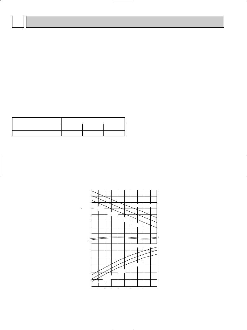
4-2. PERFORMANCE CURVE
MS24WN
MU24WN
Cooling
SHF at rating condition = 0.63
Airflow = 487CFM
Bypass Factor = 0.16
|
30 |
|
|
|
|
|
|
|
|
|
|
|
|
Btu/h) |
28 |
|
|
|
|
|
|
|
|
|
|
|
|
26 |
|
|
|
|
|
|
|
|
|
208V/230V |
|
||
24 |
Indoor |
|
|
|
|
|
|
|
|
||||
10 |
intake |
|
|
|
|
|
|
|
|
||||
|
|
|
|
|
|
|
|
|
|||||
( |
22 |
|
|
air |
WB |
|
|
|
|
|
|||
capacity |
|
|
|
|
|
temperature |
|
71 |
|||||
20 |
|
|
|
|
|
|
|||||||
|
|
|
|
|
|
|
|
||||||
|
|
|
|
|
|
|
|
67 |
|||||
|
|
|
|
|
|
|
|
|
|||||
|
|
|
|
|
|
|
|
|
|
||||
18 |
|
|
|
|
|
|
|
|
|
( |
|
63 |
|
|
|
|
|
|
|
|
|
|
°F) |
|
|||
Total |
16 |
|
|
|
|
|
|
|
|
|
|
|
|
|
|
|
|
|
|
|
|
|
|
|
|
|
|
(kW) |
2.6 |
|
|
|
|
|
|
|
|
|
208V/230V |
71 |
|
|
|
|
|
|
|
|
|
|
|
||||
consumption |
2.4 |
|
|
|
|
|
|
|
|
|
|
|
67 |
|
|
|
|
|
|
|
|
|
|
|
|
63 |
|
2.2 |
|
|
|
|
|
|
|
|
|
|
F) |
|
|
|
|
|
|
|
|
|
|
|
|
|
|
||
|
|
|
|
|
|
|
|
|
|
° |
|
||
|
|
|
|
|
|
|
|
|
|
( |
|
|
|
2.0 |
|
|
|
|
|
|
|
|
temperature |
|
|
||
|
|
|
|
|
|
|
|
|
|
|
|||
power |
1.8 |
|
|
|
|
|
|
WB |
|
|
|||
|
|
|
|
|
air |
|
|
|
|
||||
|
|
|
|
|
|
|
|
|
|
|
|||
|
|
|
|
intake |
|
|
|
|
|
|
|||
1.6 |
|
|
|
|
|
|
|
|
|
|
|||
Total |
Indoor |
|
|
|
|
|
|
|
|||||
|
|
|
|
|
|
|
|
|
|||||
|
|
|
|
|
|
|
|
|
|
||||
1.4 |
|
|
|
|
|
|
|
|
|
|
|
|
|
|
|
|
|
|
|
|
|
|
|
|
|
|
|
|
65 |
70 |
75 |
80 |
85 |
90 |
95 |
100 105 110 115 |
|||||
Outdoor intake air DB temperature (°F)
8
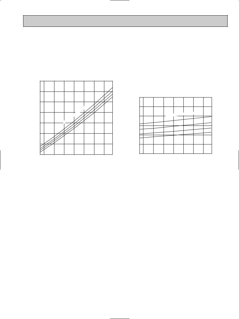
4-3. Condensing pressure
Data is based on the condition of indoor humidity 50%. Air flow should be set at High.
MU24WN |
|
|
|
|
|
|
|
|
|
(PSIG) |
|
|
|
|
|
|
|
|
300 |
|
|
|
|
|
|
|
|
|
|
|
|
|
|
|
86 |
|
280 |
|
|
|
|
|
|
80 |
|
|
|
|
|
|
|
75 |
|
|
|
|
|
|
|
|
|
|
|
|
|
|
|
|
|
|
70 |
pressure |
260 |
|
|
|
|
|
|
|
240 |
|
|
temperature |
|
|
|
||
Condensing |
|
|
|
|
|
|||
|
|
|
|
|
|
|||
|
|
Indoor |
DB |
|
|
|
|
|
220 |
|
|
|
|
|
|
||
|
|
|
|
|
|
|
||
|
|
|
|
|
|
|
|
|
|
200 |
|
|
|
|
|
|
|
|
180 |
|
|
|
|
|
|
|
|
160 |
75 |
80 |
85 |
90 |
95 |
100 |
104(°F) |
|
68 70 |
|||||||
Outdoor ambient temperature
|
(PSIG) |
|
|
|
|
|
|
|
|
100 |
|
|
|
|
|
|
|
|
90 |
|
|
|
|
|
|
|
pressure |
80 |
|
|
Indoor |
DB temperature |
|
86 |
|
|
|
|
|
|
||||
|
|
|
|
|
|
|||
|
|
|
|
|
|
|
80 |
|
70 |
|
|
|
|
|
|
|
|
Suction |
|
|
|
|
|
|
75 |
|
|
|
|
|
|
|
|
||
|
|
|
|
|
|
|
70 |
|
60 |
|
|
|
|
|
|
|
|
|
|
|
|
|
|
|
|
|
|
50 |
|
|
|
|
|
|
|
|
40 |
75 |
80 |
85 |
90 |
95 |
100 |
104(°F) |
|
68 70 |
|||||||
|
|
|
Outdoor ambient temperature |
|
|
|||
9
4-4. STANDARD OPERATION DATA
|
Model |
|
MS24WN |
||
|
|
|
|
|
|
|
Item |
Unit |
Cooling |
||
|
|
|
|
|
|
|
Capacity |
Btu / h |
22,800 |
||
Total |
|
|
|
|
|
SHF |
— |
0.63 |
|||
|
|
|
|
|
|
|
Input |
kW |
2.17 |
||
|
|
|
|
|
|
|
INDOOR UNIT MODEL |
|
MS24WN |
||
|
|
|
|
|
|
|
Power supply |
|
115V 60Hz 1[ |
||
|
|
|
|
|
|
|
Input |
kW |
0.071 |
||
|
|
|
|
|
|
|
Fan motor current |
A |
0.62 |
||
Electrical |
|
|
|
|
|
OUTDOOR UNIT MODEL |
|
MU24WN |
|||
circuit |
|
||||
|
|
|
|
||
|
Power supply |
|
208/230V 60Hz 1[ |
||
|
|
|
|
|
|
|
Input |
kW |
2.099 |
||
|
|
|
|
|
|
|
Comp. current |
A |
9.36/ 8.30 |
||
|
|
|
|
|
|
|
Fan motor current |
A |
0.67/0.71 |
||
|
|
|
|
|
|
|
Condensing pressure |
PSIG |
250 |
||
|
|
|
|
|
|
|
Suction pressure |
PSIG |
71 |
||
|
|
|
|
|
|
|
Discharge temperature |
˚F |
174 |
||
|
|
|
|
|
|
Refrigerant |
Condensing temperature |
˚F |
115 |
||
|
|
|
|
||
circuit |
Suction temperature |
˚F |
48 |
||
|
|
|
|
||
|
Comp. shell bottom temp |
˚F |
158 |
||
|
|
|
|
||
|
Ref. pipe length |
ft. |
25 |
||
|
|
|
|
||
|
Refrigerant charge (R22) |
— |
4 Ib. 5 oz. |
||
|
|
|
|
|
|
|
Intake air temperature |
DB |
˚F |
80 |
|
|
|
|
|
||
|
WB |
˚F |
67 |
||
|
|
||||
|
|
|
|
|
|
Indoor |
Discharge air temperature |
DB |
˚F |
51 |
|
|
|
|
|||
unit |
WB |
˚F |
50 |
||
|
|||||
|
|
|
|
|
|
|
Fan speed (High) |
rpm |
1,280 |
||
|
|
|
|
|
|
|
Airflow (High) |
CFM |
487(Wet) |
||
|
|
|
|
|
|
|
Intake air temperature |
DB |
˚F |
95 |
|
|
|
|
|
||
Outdoor |
WB |
˚F |
— |
||
|
|||||
|
|
|
|
||
unit |
Fan speed |
rpm |
750/820 |
||
|
|
|
|
|
|
|
Airflow |
CFM |
1,589/1,765 |
||
|
|
|
|
|
|
POWER SUPPLY
MS24WN •Both wirings can be applied. |
|
|
Control voltage |
|
INDOOR UNIT 115V 60Hz 1[, |
INDOOR UNIT |
|
Power supply voltage to |
|
|
2wires |
|
|
|
|
|
|
Disconnect switch |
serial signal circuit is 12V DC. |
|
|
|
Voltage between 1+ and 3-- |
|
|
|
|
SIGNAL WIRE |
|
|
|
|
on in-out terminal block will be |
|
|
|
|
2 wires 12V DC |
|
OUTDOOR UNIT |
SIGNAL WIRE |
OUTDOOR UNIT |
115V 60Hz 1[, |
12V DC peak. |
|
2 wires 12V DC |
|
2 wires |
|
|
|
|
115V |
|
|
208/230V |
|
208/230V |
|
|
60Hz 1[, 3 wires |
|
60Hz 1[, 3 wires |
|
10
4-5. OPERATING RANGE
(1) POWER SUPPLY
|
Model |
Rating |
|
Guaranteed Voltage |
|||||||
|
|
|
|
|
|
|
|
|
|
|
|
Indoor unit |
MS24WN |
115V 60Hz 1[ |
Min. 103V |
|
115V Max. 127V |
||||||
|
|
|
|
|
|
|
|
|
|||
|
|
|
|
|
|
|
|
|
|||
|
|
|
|
|
|
|
|
|
|
|
|
|
|
|
|
|
|
|
|
|
|
|
|
Outdoor unit |
MU24WN |
208/230V 60Hz 1[ |
Min. 198V |
208V 230V Max. 253V |
|||||||
|
|
|
|
|
|
|
|
|
|||
|
|
|
|
|
|
|
|
|
|||
|
|
|
|
|
|
|
|
|
|
|
|
|
|
|
|
|
|
|
|
|
|
|
|
(2) OPERATION
|
Intake air |
|
Indoor |
|
Outdoor |
Function |
temperature |
|
|
||
|
|
|
|
||
|
|
|
|
|
|
|
Condition |
DB (˚F) |
WB (˚F) |
DB (˚F) |
WB (˚F) |
|
|
|
|
|
|
|
Standard temperature |
80 |
67 |
95 |
— |
Cooling |
Maximum temperature |
95 |
71 |
115 |
— |
|
|
|
|
|
|
|
Minimum temperature |
67 |
57 |
67 |
— |
|
Maximum humidity |
|
78% |
|
— |
4-6. OUTLET AIR SPEED AND COVERAGE RANGE
Model |
Mode |
Function |
Air flow |
Air speed |
Coverage |
|
(CFM) |
(ft./sec.) |
range (ft.) |
||||
|
|
|
||||
MS24WN |
FAN |
Dry |
565 |
20.1 |
34.2 |
|
COOL |
Wet |
487 |
17.2 |
29.4 |
||
|
●The air coverage range is the figure up to the position where the air speed is 1 ft./sec., when air is blown out horizontally from the unit properly at the High speed position.
The coverage range should be used only as a general guideline since it varies according to the size of the room and furniture arranged in the room.
4-7. ADDITIONAL REFRIGERANT CHARGE (R22(oz.))
|
Outdoor unit |
|
|
Refrigerant piping length (one way) |
|
|||
Model |
precharged |
|
|
|
|
|
|
|
|
|
|
|
|
|
|
||
|
(up to 25ft.) |
25ft. |
30ft. |
|
35ft. |
40ft. |
45ft. |
50ft. |
|
|
|
|
|
|
|
|
|
MS24WN MU24WN |
4 lb. 5 oz. |
0 |
0.81 |
|
1.62 |
2.43 |
3.24 |
4.05 |
|
|
|
|
|
|
|
|
|
CALCULATION : Xoz. = 0.81/ 5oz./ft. x (Additional Piping Length-25) ft.
11

5 
 OUTLINES AND DIMENSIONS
MS24WN Unit: inch
INDOOR UNIT
|
Installation plate |
Indoor unit |
|
|
|
|
3-7/8 |
|
|
|
6-13/16 |
5/16 |
|
|
|
|
|
|
|
|
42-1/16 |
|
|
|
|
10-1/16 |
12-3/8 |
|
|
|
|
|
||
1-7/8 |
16-5/16 |
|
16-5/16 |
1/8 |
1-7/8 |
|
3-7/8 |
|
|
|
|
||
|
|
|
|
6-13/16 |
|
|
|
Wall hole [ 2-15/16 |
|
|
|
||
43-5/16 |
8-7/8 |
3/16 |
|
|
|
|
|
|
|
|
|
|
|
|
|
|
Installation plate |
|
|
|
|
|
|
|
Liquid line [ 3/8 19-11/16 |
|
13/16 |
|
Air in |
|
Gas line |
[ 3/4 16-15/16 |
|
|
{Insulation |
[ 1-1/4 I.D |
||
|
|
|
|
[ 1-15/16 O.D |
|
12- |
|
|
|
|
|
2-3/16 |
31-1/8 |
9-15/16 |
8-15/16 |
Drain hose [5/8 |
|
|
|
|
|||
|
|
Air out |
(Connected part O.D) |
||
|
|
|
|||
|
|
|
|
Insulation [ 1-1/8 |
|
2-5/16 |
3/4 |
|
|
|
|
6-3/8 |
|
|
|
|
|
Wireless remote controller |
|
|
|
|
|
12
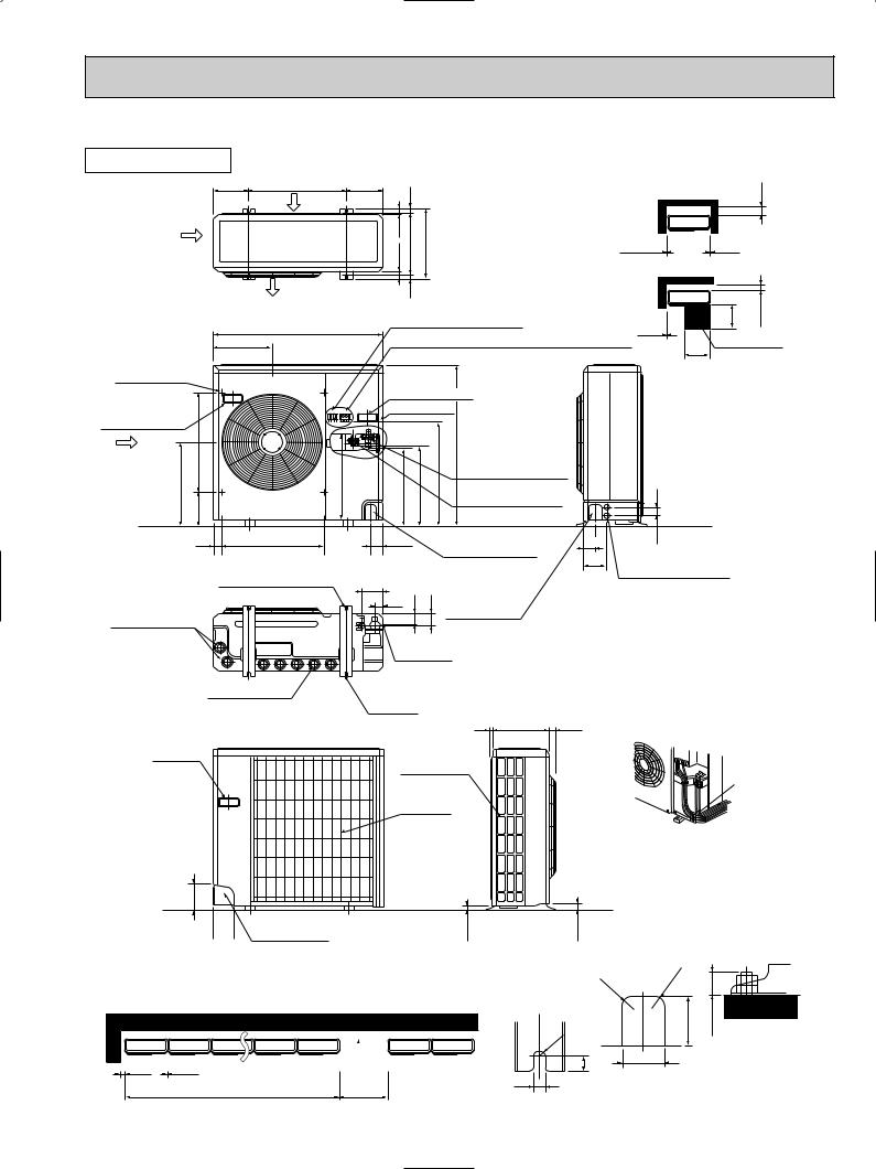
MU24WN
OUTDOOR UNIT
7-9/32 |
19-11/16 |
7-9/32 |
|
11/16 |
|
|
Air intake |
|
|
|
|
Air intake |
|
|
9/161-1/16 |
13 |
14-1/4 |
|
|
|
|
|
|
|
|
|
1- |
|
|
Unit: inch
Outdoor Unit-Necessary surrounding clearance
|
7-7/8 |
|
Note:Allow adequate |
13/32 |
13/32 upper clearance |
Front opening
Air outlet
|
9/16 |
34-1/4 |
Terminal block for power line |
13/32 |
19-11/16 |
5-29/32 |
11-7/8 |
Terminal block for indoor and outdoor unit connection |
Service space |
|
|
19-11/16 |
Outlet guide |
|
|
|
|
|
|
installation hole |
|
|
|
|
|
|
|
|
|
Handle for moving |
|
||
|
|
|
Service panel |
|
||
Handle for moving |
|
|
|
|
|
|
A |
1/18-720-5/8 |
7/18-18 |
17/32-17 23/32-17 |
3/4-21 |
33-1/2 |
3/4-1 |
3/8-17 |
||||||
|
|
|
|
|
Refrigerant-pipe flared |
|
|
|
|
|
|
connection [5/8 |
|
|
|
|
|
|
Refrigerant-pipe flared |
|
|
|
|
|
|
connection [3/8 |
|
|
|
|
|
|
for front piping |
1/16-2 |
1-9/16 |
20-5/8 |
2-3/8 |
|
Knock out hole |
2-3/8 |
|
|
|
|
|
|
(refrigerant,drainage |
4-3/4 Knock out holes for |
|
|
|
|
|
power line 2-[1-1/16 |
|
|
|
2-1/2o7/8 Oval holes |
4-1/8 |
|
and wiring) |
|
|
|
-13/4 |
|
|
||
|
|
(standard bolt M10) |
-15/8 |
|
|
|
|
|
|
1-5/16 |
|
Knock out hole |
|
Drain hole [1-5/16 |
|
|
|
for right piping |
|
|
|
|
|
(refrigerant,drainage |
|
||
|
|
|
Bottom |
and wiring) |
|
|
|
|
|
|
|
||
|
|
|
piping hole |
|
||
Drain hole [1-5/16
Handle for moving
5-7/16

 Rear piping hole 3-3/4
2-U-shaped notched holes
9/32 11-5/8 15/16
A
Side air intake
Conduit hole
Rear fresh air intake
NOTE: Do not wire12V DC and
115V AC in same conduit hole.
15/16 |
1-5/16 |
Outdoor Unit-Necessary surrounding clearance
(Concentrated installation) The upper side must be open.
|
|
7-7/8 |
R1/4 |
4 |
13/32 |
|
|
|
|
1/2
For 10 units or less |
39-3/8 |
R13/16 |
R13/16 |
3-1/8 |
1 max. |
Standard bolt length
11/16 |
2-9/16 |
|
Front right piping holesdetail figures
13
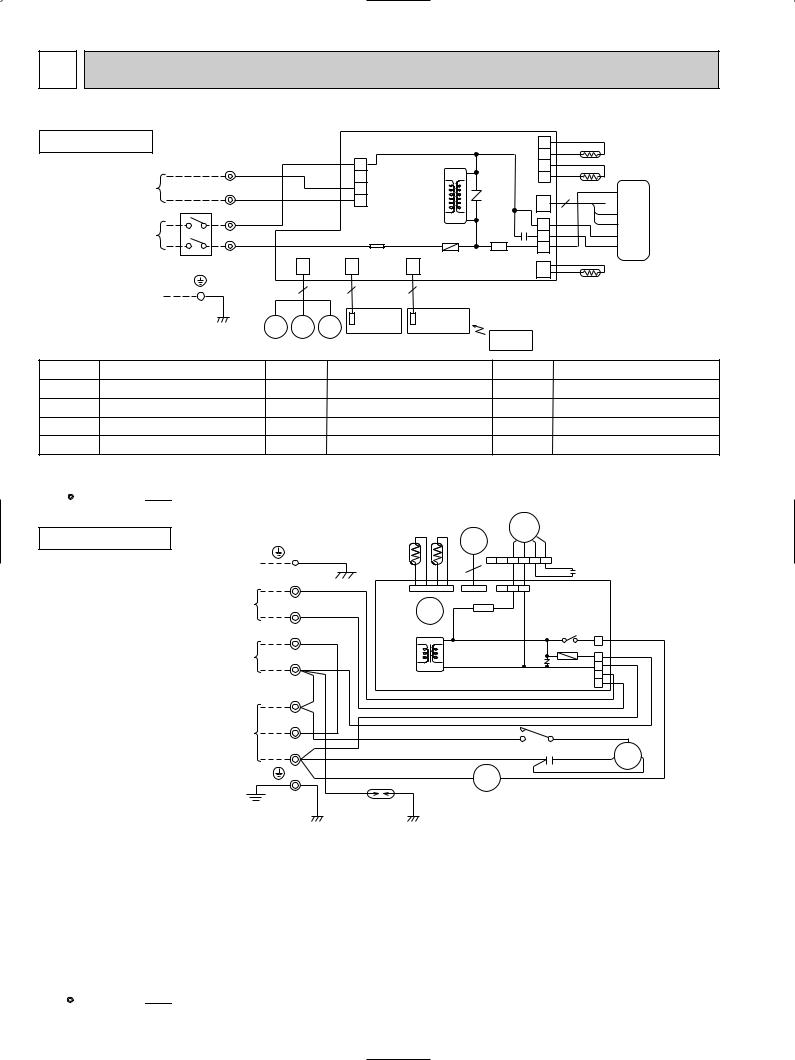
6 |
WIRING DIAGRAM |
|
|
|
|
|
|
|
|||
MS24WN |
MODEL WIRING DIAGRAM |
|
|
|
|
|
|||||
INDOOR UNIT |
|
|
|
|
CN201 |
|
|
4 |
|
RT13 |
|
|
|
|
|
|
|
|
|
3 |
|
||
|
|
TB |
|
|
|
HIC1 |
|
|
|
||
|
TO OUTDOOR |
ORN |
|
|
1 |
|
2 |
|
RT12 |
||
|
3+ |
|
|
2 |
|
|
1 |
|
|||
|
UNIT |
|
|
|
|
|
|
|
|
||
|
CONNECTING |
|
|
|
|
3 |
|
CN112 |
BLK |
||
|
WIRES |
1- |
VLT |
|
|
|
|||||
|
12V DC |
|
|
4 |
NR11 |
CN |
3 |
GRY |
|||
|
FROM OUTDOOR |
w |
|
|
|
|
|
|
121 |
|
YLW |
|
UNIT |
N |
BLK |
|
|
|
TRANS |
C11 |
1 |
|
BRN MF |
|
CONNECTING |
|
|
|
|
|
|
|
WHT |
||
|
WIRES |
L1 |
RED |
|
|
TAB12 |
F11 SR141 |
3 |
|
||
|
|
|
|
RED |
|||||||
|
POWER |
|
|
|
|
|
|
|
4 |
|
|
(SUPPLY) |
|
|
|
|
|
|
|
|
|
||
|
|
|
|
|
|
CN211 |
|
|
|||
|
115V |
|
|
CN |
|
CN |
CN |
|
|
||
|
|
|
|
|
CN |
|
|
||||
|
1 phase |
|
|
|
|
|
RT11 |
||||
|
|
|
151 |
|
102 |
|
|
|
|||
|
|
|
|
101 ELECTRONIC CONTROL P.C. BOARD 111 |
|
||||||
|
60Hz |
|
|
|
|
|
|
|
|
|
|
|
TO OUTDOOR |
|
|
15 |
|
3 |
3 |
|
|
|
|
|
UNIT |
|
|
|
|
|
|
|
|
|
|
|
CONNECTING |
|
|
|
|
|
|
|
|
|
|
|
WIRE |
|
|
|
|
DISPLAY |
RECEIVER |
|
|
|
|
|
|
|
|
MV2 MV2 |
MV1 |
P.C.BOARD |
P.C.BOARD |
|
|
|
|
|
|
|
|
|
|
REMOTE |
|
|
|
||
w A disconnect may be required by local code. |
|
|
|
|
|
|
|||||
|
|
|
CONTROLLER |
|
|
|
|||||
SYMBOL |
NAME |
|
SYMBOL |
|
NAME |
SYMBOL |
|
NAME |
|||
C11 |
INDOOR FAN CAPACITOR |
MV1 |
VANE MOTOR(HORIZONTAL) |
RT12 |
|
INDOOR COIL THERMISTOR(MAIN) |
|||||
F11 |
FUSE(3.15A) |
|
|
MV2 |
VANE MOTOR(VERTICAL) |
RT13 |
|
INDOOR COIL THERMISTOR(SUB) |
|||
HIC1 |
DC/DC CONVERTER |
|
NR11 |
VARISTOR |
|
SR141 |
SOLID STATE RELAY |
||||
MF |
INDOOR FAN MOTOR (INNER PROTECTOR) |
RT11 |
ROOM TEMPERATURE THERMISTOR |
TB |
|
TERMINAL BLOCK |
|||||
NOTE:1. About the outdoor side electric wiring, refer to the outdoor unit electric wiring diagram for servicing. |
|
|
|
SG79J618H02 |
|||||||
2.Use copper conductors only.(For field wiring)
3.Symbols below indicate;
:Terminal block, 


 : Connector
MU24WN |
MODEL WIRING DIAGRAM |
|
|
|
|
|
|
MF |
|
|
|
|
|||||
OUTDOOR UNIT |
|
|
|
|
|
RT62 |
RT63 |
|
|
|
|
|
|
|
|
||
|
|
|
|
|
LEV |
|
|
|
|
|
|
|
|
||||
|
|
|
|
|
|
|
|
BLK |
WHT |
ORN |
RED |
|
|
|
|||
|
|
|
|
|
|
|
|
|
|
|
|
|
|
||||
|
FROM INDOOR UNIT |
|
|
|
|
|
|
6 |
6 |
5 |
4 |
3 |
2 |
1 |
RED |
|
|
|
CONNECTING WIRE |
|
|
|
|
|
|
|
|
BLK |
WHT |
|
|
ORN |
C2 |
|
|
|
|
|
|
|
|
|
|
|
|
|
|
|
|
|
|||
|
|
TB2 |
|
|
|
|
|
|
|
|
|
|
|
|
|
||
|
|
+ |
|
|
|
|
|
|
|
|
|
|
|
|
|
|
|
|
|
3 |
|
|
CN662 |
CN724 |
1 |
2 |
3 |
CN711 |
|
|
|||||
|
|
|
|
|
|
|
|
||||||||||
|
FROM INDOOR UNIT |
|
|
|
|
|
|
|
|
|
|
|
|
|
|
|
|
|
CONNECTING WIRES |
1 |
- |
|
|
X52 |
|
SR61 |
|
|
|
|
|
|
|
|
|
|
12V DC |
|
|
|
|
|
|
|
|
|
|
|
|||||
|
|
|
|
|
|
|
|
|
|
|
|
|
|||||
|
|
N |
|
|
|
|
|
|
|
|
|
|
|
|
X52 |
TAB52 |
|
|
TO INDOOR UNIT |
|
|
|
|
|
|
|
|
|
|
|
|
|
|
||
|
|
|
|
|
|
|
|
|
|
|
|
|
COM |
NO |
|
||
|
|
|
|
|
|
|
|
|
|
|
|
|
|
|
|||
|
CONNECTING |
|
|
|
|
|
|
|
|
|
|
|
|
|
|
||
|
|
|
BLK |
|
|
|
|
|
|
|
|
|
|
F61 |
|
||
|
WIRES |
L1 |
|
|
T61 |
|
|
|
|
|
|
NR61 |
|
|
1 |
||
|
115V |
|
|
|
|
|
|
|
|
|
|
|
|
|
3 |
||
|
1 phase 60Hz |
TB1 |
RED |
|
|
|
|
|
|
|
|
|
|
|
CN730 |
5 |
|
|
|
|
|
|
|
|
|
|
|
|
|
|
ORN |
7 |
|||
|
|
|
|
|
|
OUTDOOR ELECTRONIC CONTROL P.C. BOARD |
|||||||||||
|
|
L1 |
|
|
|
|
|
|
|
|
|
|
|
|
VLT |
|
|
|
|
|
|
|
|
|
|
|
|
|
|
|
|
|
|
|
|
|
|
|
|
|
|
|
|
|
|
|
|
|
|
|
BLU |
|
|
|
POWER |
N |
|
|
|
|
|
|
|
|
|
|
|
|
RED |
|
|
|
|
|
|
|
|
|
|
|
|
|
|
|
|
|
|
||
|
SUPPLY |
|
|
RED |
|
|
|
|
|
|
|
|
|
|
WHT |
|
|
|
|
|
|
|
|
|
|
|
|
|
|
|
|
C |
|||
|
208/230V |
|
|
|
|
|
|
|
|
|
|
|
|
|
|||
|
|
|
|
|
|
|
|
|
|
|
1 |
52C |
2 |
|
|||
|
1 phase 60Hz |
L2 |
|
|
BLU |
|
|
|
|
|
|
RED |
S MC R |
||||
|
|
|
|
|
|
|
|
|
|
|
C1 |
|
|||||
|
|
|
|
|
BLU |
|
|
A2 |
|
|
A1 |
|
|
|
|
BLK |
|
|
|
|
|
|
|
|
52C |
|
|
|
|
|
|
|
|||
|
|
|
|
|
DSAR |
|
|
|
|
|
|
|
|
|
|
|
|
|
|
|
GRN/YLW |
RED |
|
|
|
|
|
|
|
|
|
|
|
|
|
|
GROUND |
|
|
|
|
|
|
|
|
|
|
|
|
|
|
||
|
|
|
|
|
|
|
|
|
|
|
|
|
|
|
|
||
BLU
SYMBOL |
NAME |
SYMBOL |
NAME |
SYMBOL |
NAME |
|
|
|
|
|
|
C1 |
COMPRESSOR CAPACITOR |
MF |
OUTDOOR FAN MOTOR(INNER PROTECTOR) |
TB2 |
TERMINAL BLOCK |
C2 |
OUTDOOR FAN CAPACITOR |
NR61 |
VARISTOR |
T61 |
TRANSFORMER |
|
|
|
|
|
|
DSAR |
SURGE ABSORBER |
RT62 |
DISCHARGE TEMPERATURE THERMISTOR |
X52 |
COMPRESSOR AUXILIARY RELAY |
|
|
|
|
|
|
F61 |
FUSE(3.15A) |
RT63 |
AMBIENT TEMPERATURE THERMISTOR |
52C |
COMPRESSOR CONTACTOR |
LEV |
EXPANSION VALVE COIL |
SR61 |
SOLID STATE RELAY |
|
|
MC |
COMPRESSOR(INNER PROTECTOR) |
TB1 |
TERMINAL BLOCK |
|
|
NOTE:1. About the indoor side electric wiring, refer to the indoor unit electric wiring diagram for servicing. |
|
SG79J606H02 |
|||
2.Use copper conductors only.(For field wiring)
3.Symbols below indicate;
:Terminal block, 


 : Connector
14
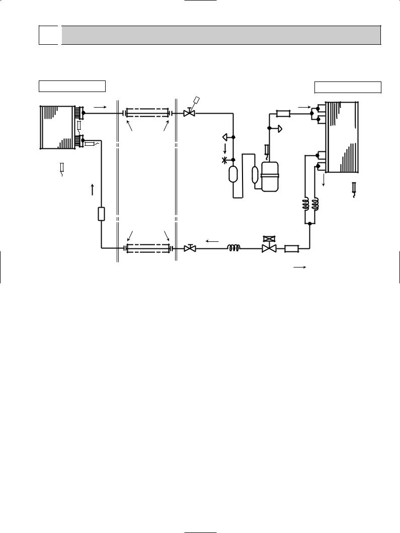
7 
 REFRIGERANT SYSTEM DIAGRAM
|
|
|
|
|
|
|
Unit: inch |
MS24WN |
|
|
|
|
|
|
MU24WN |
INDOOR UNIT |
Refrigerant pipe [5/8 |
|
|
|
|
OUTDOOR UNIT |
|
|
|
|
|
|
Strainer |
|
|
|
|
(with heat insulator) |
|
|
|
|
|
|
|
|
|
|
|
#100 |
|
Indoor |
Indoor coil |
|
Stop valve |
|
|
SERVICE |
|
thermistor |
|
(with service port) |
|
|
|||
heat |
|
Discharge |
Outdoor |
||||
exchanger |
RT12(main) |
Flared connection |
SERVICE |
PORT |
heat |
||
temperature |
|
||||||
|
|
|
PORT |
|
thermistor |
|
exchanger |
|
|
|
|
|
|
||
|
Indoor coil |
|
FUSIBLE |
RT62 |
|
|
|
|
thermistor |
|
|
|
|
||
|
RT13(sub) |
|
PLUG |
|
|
|
|
Room temperature |
|
Accumulator |
|
|
|
||
thermistor |
|
|
|
|
Ambient |
||
RT11 |
|
|
|
|
Compressor |
||
|
|
|
|
|
temperature |
||
|
|
|
|
|
|
|
|
|
|
|
|
|
Capillary tube |
|
thermistor |
|
Strainer |
|
|
|
O.D.0.16 I.D.0.09 7-7/8 |
RT63 |
|
|
|
|
|
(Upper path) |
|
Capillary tube |
|
|
#50 |
|
|
|
|
||
|
|
|
|
|
|
O.D.0.16 I.D.0.09 3-15/16 |
|
|
|
Flared connection |
|
|
|
|
|
|
|
|
|
LEV |
(Lower path) |
||
|
|
|
|
|
|||
|
|
|
|
|
|
||
|
|
|
|
|
|
Strainer |
|
|
|
|
|
|
|
#100 |
|
|
|
|
Stop valve |
Capillary tube |
|
|
|
|
|
Refrigerant pipe [3/8 |
|
O.D.0.14 I.D.0.09 1-31/32 |
|
||
|
|
|
|
|
Refrigerant flow in cooling |
||
|
|
(with heat insulator) |
|
|
|
||
|
|
|
|
|
|
|
|
15
 Loading...