


SPLIT-TYPE, AIR CONDITIONERS
No. OB325
SERVICE MANUAL
Wireless type
Models
MS-A18WV MS-A24WV MS-A30WV
-E1 (WH)
-E1 (WH)
-E1 (WH)
CONTENTS
Indication of model name
MS-A18WV - E1
MS-A24WV - E1
MS-A30WV - E1
1.TECHNICAL CHANGES ················
2.PART NAMES AND FUNCTIONS············
3.SPECIFICATION····················
4.NOISE CRITERIA CURVES ···············
5.OUTLINES AND DIMENSIONS ·············
6.WIRING DIAGRAM ··················
7.REFRIGERANT SYSTEM DIAGRAM ···········
8.MICROPROCESSOR CONTROL ············
9.SERVICE FUNCTIONS ·················
10.TROUBLESHOOTING·················
11.DISASSEMBLY INSTRUCTIONS·············
12.PARTS LIST······················
13.OPTIONAL PARTS···················
NOTE:
This service manual describes technical data of the indoor units.
As for outdoor units MU-A18WV- E1 , MU-A24WV- E1 and MU-A30WV- E1 , refer to service manual OB326.
1 
 TECHNICAL CHANGES
MS-18RV - E1 MS-A18WV - E1
1.Indoor unit model has changed.
2.Rated voltage has changed. (220V-240V 230V)
3.Remote controller has changed.
•LONG MODE and WIDE MODE have been added.
4.Indoor fan motor has changed.(RA4V27-EF RC4V32-AA)
5.Indoor heat exchanger has changed.
6.Diameter of connect pipe has changed.(Liquid:[8 [6.35)
7.Air filter has changed to catechin air filter.
MS-24RV - E1 MS-A24WV - E1
1.Indoor unit model has changed.
2.Rated voltage has changed. (220V-240V 230V)
3.Remote controller has changed.
•LONG MODE and WIDE MODE have been added.
4.Indoor fan motor has changed.(RA4V27-EE RC4V32-AA)
5.Indoor heat exchanger has changed.
6.Diameter of connect pipe has changed.(Liquid:[8 [6.35)
7.Air filter has changed to catechin air filter.
MS-30RV - E1 MS-A30WV - E1
1.Diameter of connect pipe has changed.(Gas:[15.88 [12)
2.Rated voltage has changed. (220V-240V 230V)
3.Power supply cord has been added.
4.Air filter has changed to catechin air filter.
2 
 PART NAMES AND FUNCTIONS
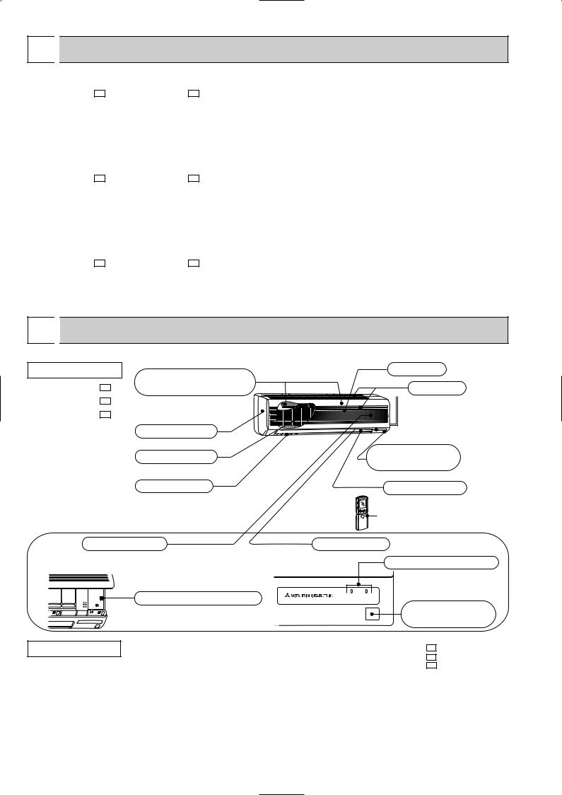
INDOOR UNIT
MS-A18WV - E1 MS-A24WV - E1 MS-A30WV - E1
Air cleaning filter (option) (White bellows type)
Front panel
Catechin air filter
Vertical vanes
Grille
Air inlet
Remote control receiving section
Horizontal vane
Remote controller
Operation section |
Display section |
(When the grille is opened) |
Operation indicator lamp |
|
|
Emergency operation switch |
Operation Indicator |
|
|
|
Remote control |
|
receiving section |
ACCESSORIES
Indoor unit
|
|
MS-A18WV- E1 |
|
|
MS-A24WV- E1 |
|
|
MS-A30WV- E1 |
1 |
Installation plate |
1 |
2 |
Installation plate fixing screw 4 o 25 mm |
7 |
3 |
Remote controller holder |
1 |
4 |
Fixing screw for 3 o 3.5 o 1.6 mm (Black) |
2 |
5 |
Battery (AAA) for remote controller |
2 |
|
|
|
6 |
Wireless remote controller |
1 |
|
|
|
7 |
Felt tape (Used for left or left-rear piping) |
1 |
|
|
|
2

REMOTE CONTROLLER
MS-A18WV - E1
MS-A24WV - E1
MS-A30WV - E1
Signal transmitting section
Operation display section
OPERATE/ STOP
(ON/ OFF)button
|
|
PM |
|
|
AM |
ON/OFF |
TOO |
TOO |
|
WARM |
COOL |
TEMPERATURE buttons
Open the front lid. |
VANE button (Horizontal vane button)
OPERATION SELECT button
ECONO COOL button
WIDE VANE button (Vertical vane button)
RESET button
Indication of remote controller model is on back.
AM |
ON/OFF |
TOO |
TOO |
|
WARM |
COOL |
|
FAN |
STOP |
FAN SPEED CONTROL button |
|
|
||
I FEEL COOL |
|
|
OFF-TIMER button |
|
VANE |
START |
|
|
|
||
FAN DRY |
|
|
ON-TIMER button |
|
|
|
|
MODE |
WIDE VANE |
HR. |
HR. button |
|
|
|
|
ECONO COOL |
LONG |
MIN. |
MIN. button |
|
|
|
(TIME SET button) |
|
RESET CLOCK |
|
CLOCK SET button |
|
|
|
|
|
|
|
LONG button |

3 SPECIFICATION
|
|
Indoor model |
|
|
|
|
Function |
|
|
|
|
Power supply |
|
|
Capacity Air flow(High/Med.w/Loww) |
K /h |
|||
|
|
Power outlet |
A |
|
Electrical |
|
Running current |
A |
|
data |
Power input |
W |
||
Auxiliary heater |
A(kW) |
|||
Power factor |
% |
|||
|
|
|||
|
|
Fan motor current |
A |
|
|
motor |
Model |
|
|
Fan |
Winding |
" |
||
resistance(at20:) |
||||
|
|
|
||
|
|
Dimensions WOHOD |
mm |
|
|
|
Weight |
kg |
|
|
|
Air direction |
|
|
Special |
remarks |
Sound level(High/Med.w/Loww) |
dB |
|
Fan speed(High/Med.w/Loww) |
rpm |
|||
Fan speed regulator |
|
|||
Thermistor RT11(at25:) |
k" |
|||
|
|
|||
|
|
Thermistor RT12(at25:) |
k" |
|
|
|
Remote controller model |
|
|
MS-A18WV - E1 |
MS-A24WV - E1 |
Cooling |
Cooling |
Single phase |
Single phase |
230V, 50Hz |
230V, 50Hz |
768/642w/528w |
768/672w/588w |
10 |
10 |
0.30 |
0.30 |
60 |
60 |
— |
— |
87 |
87 |
0.30 |
0.30 |
RC4V32-AA |
RC4V32-AA |
WHT-BLK 293 |
WHT-BLK 293 |
BLK-RED 146 |
BLK-RED 146 |
1,100O325O227 |
1,100O325O227 |
16 |
16 |
5 |
5 |
42/38w/34w |
45/41w/37w |
1,070/920w/780w |
1,070/960w/850w |
3 |
3 |
10 |
10 |
10 |
10 |
KP0B or KG1D |
KP0B or KG1D |
Indoor model
Function
Power supply
Capacity Air flow(High/Med.w/Loww) |
K /h |
|||
|
|
Power outlet |
A |
|
Electrical |
data |
Running current |
A |
|
Power input |
W |
|||
|
|
|||
|
|
Auxiliary heater |
A(kW) |
|
|
|
Power factor |
% |
|
|
|
Fan motor current |
A |
|
Fan |
motor |
Model |
" |
|
Winding |
||||
|
|
|
||
|
|
resistance(at20:) |
|
|
|
|
Dimensions WOHOD |
mm |
|
|
|
Weight |
kg |
|
|
|
Air direction |
|
|
|
|
Sound level(High/Med.w/Loww) |
dB |
|
Special |
remarks |
Fan speed(High/Med.w/Low w) |
rpm |
|
Thermistor RT11(at25:) |
k" |
|||
|
|
Fan speed regulator |
|
|
|
|
Thermistor RT12(at25:) |
k" |
|
|
|
Thermistor RT13(at25:) |
k" |
|
|
|
Remote controller model |
|
|
MS-A30WV - E1
Cooling
Single phase 230V, 50Hz
960/822w/684 w
10
0.34
69
—
88
0.34
RC4V40-AA
WHT-BLK 138.2 BLK-RED 159.0
1,100O325O227
16
5
47/42 w /37 w
1,280/1,130w/970 w
3
10
10
10
KP0B or KG1D
NOTE: 1. Test conditions are based on JIS C 9612.
Cooling : Indoor DB27°C WB19°C
Outdoor DB35°C WB(24°C)
Indoor-Outdoor piping length 5m
2.Remote controller model KP0B and KG1D are the same in terms of specification. w Reference value
4

4 
 NOISE CRITERIA CURVES
MS-A18WV- E1 |
MS-A24WV- E1 |
FAN SPEED SPL(dB(A)) |
LINE |
High 42
FAN SPEED SPL(dB(A)) |
LINE |
High 45
Test conditions, |
Test conditions, |
Cooling : Dry-bulb temperature 27: Wet-bulb temperature 19: |
Cooling : Dry-bulb temperature 27: Wet-bulb temperature 19: |
BAR |
90 |
|
|
|
|
|
|
|
|
BAR |
90 |
|
|
|
|
|
|
|
|
|
|
||
MICRO |
80 |
|
|
|
|
|
|
|
|
MICRO |
80 |
|
|
|
|
|
|
|
|
|
|
||
0.0002 |
70 |
|
|
|
|
|
|
|
NC-70 |
0.0002 |
70 |
|
|
|
|
|
|
|
|
|
|||
dB re |
60 |
|
|
|
|
|
|
|
|
dB re |
60 |
LEVEL, |
|
|
|
|
|
|
|
|
LEVEL, |
||
|
|
|
|
|
|
|
|
NC-60 |
|
||
50 |
|
|
|
|
|
|
|
|
|
||
PRESSURE |
|
|
|
|
|
|
|
|
PRESSURE |
50 |
|
|
|
|
|
|
|
|
|
NC-50 |
|
||
40 |
|
|
|
|
|
|
|
|
40 |
||
|
|
|
|
|
|
|
|
NC-40 |
|
||
SOUND |
|
|
|
|
|
|
|
|
SOUND |
|
|
30 |
|
|
|
|
|
|
|
|
30 |
||
BAND |
|
|
|
|
|
|
|
|
NC-30 |
BAND |
|
20 |
APPROXIMATE |
|
|
|
|
|
|
20 |
|||
OCTAVE |
|
|
|
|
|
|
OCTAVE |
||||
THRESHOLD OF |
|
|
|
|
|
|
|||||
|
|
|
|
|
|
|
|
||||
|
HEARING FOR |
|
|
|
|
|
NC-20 |
|
|||
|
CONTINUOUS |
|
|
|
|
|
|
|
|||
10 |
NOISE |
|
|
|
|
|
|
|
10 |
||
|
63 |
125 |
250 |
500 |
1000 |
2000 |
4000 |
8000 |
|
||
|
|
|
|
||||||||
|
|
|
|
|
|
|
NC-70 |
|
|
|
|
|
|
|
NC-60 |
|
|
|
|
|
|
|
NC-50 |
|
|
|
|
|
|
|
NC-40 |
|
|
|
|
|
|
|
NC-30 |
APPROXIMATE |
|
|
|
|
|
|
|
THRESHOLD OF |
|
|
|
|
|
|
|
HEARING FOR |
|
|
|
|
|
NC-20 |
|
CONTINUOUS |
|
|
|
|
|
|
|
NOISE |
|
|
|
|
|
|
|
63 |
125 |
250 |
500 |
1000 |
2000 |
4000 |
8000 |
BAND CENTER FREQUENCIES, Hz |
BAND CENTER FREQUENCIES, Hz |
MS-A30WV- E1
FAN SPEED SPL(dB(A)) |
LINE |
High 47
Test conditions,
Cooling : Dry-bulb temperature 27: Wet-bulb temperature 19:
BAR |
90 |
|
|
|
|
|
|
|
|
|
|
|
|
|
|
|
|
|
|
MICRO |
80 |
|
|
|
|
|
|
|
|
|
|
|
|
|
|
|
|
|
|
0.0002 |
70 |
|
|
|
|
|
|
|
NC-70 |
|
|
|
|
|
|
|
|
||
dB re |
60 |
|
|
|
|
|
|
|
|
LEVEL, |
|
|
|
|
|
|
|
|
|
|
|
|
|
|
|
|
|
NC-60 |
|
50 |
|
|
|
|
|
|
|
|
|
PRESSURE |
|
|
|
|
|
|
|
|
|
|
|
|
|
|
|
|
|
NC-50 |
|
40 |
|
|
|
|
|
|
|
|
|
|
|
|
|
|
|
|
|
NC-40 |
|
SOUND |
|
|
|
|
|
|
|
|
|
30 |
|
|
|
|
|
|
|
|
|
BAND |
|
|
|
|
|
|
|
|
NC-30 |
20 |
APPROXIMATE |
|
|
|
|
|
|
||
OCTAVE |
|
|
|
|
|
|
|||
THRESHOLD OF |
|
|
|
|
|
|
|||
|
|
|
|
|
|
|
|||
|
HEARING FOR |
|
|
|
|
|
NC-20 |
||
|
CONTINUOUS |
|
|
|
|
|
|
||
10 |
NOISE |
|
|
|
|
|
|
|
|
|
63 |
125 |
250 |
500 |
1000 |
2000 |
4000 |
8000 |
|
|
|
||||||||
BAND CENTER FREQUENCIES, Hz
INDOORUNIT
WALL
1m
0.8m
MICROPHONE
5
5 
 OUTLINES AND DIMENSIONS
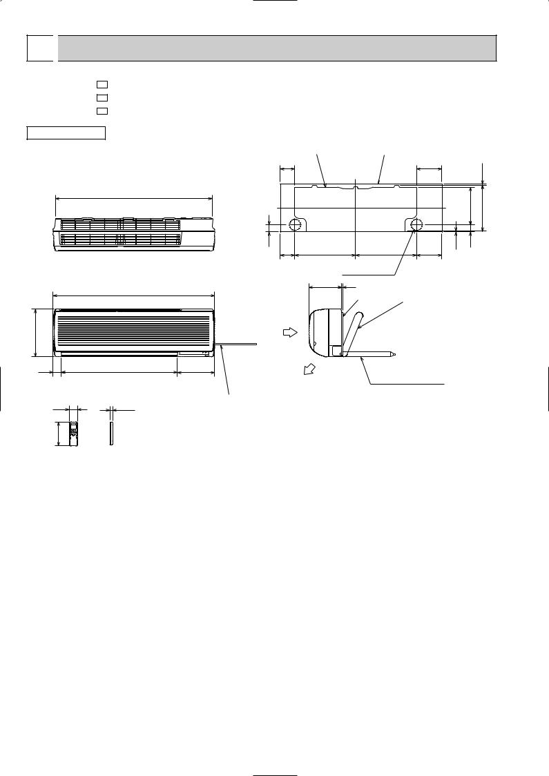
MS-A18WV - E1
MS-A24WV - E1
MS-A30WV - E1
INDOOR UNIT
1068
1100
325
56 |
791 |
58 |
19 |
162 |
|
Wireless remote controller
Unit: mm
Installation plate |
Indoor unit |
|
|
|
|
98 |
|
|
173 |
|
7.5 |
|
|
|
|
|
|
|
|
|
|
255.5 |
315 |
47 |
414.5 |
414.5 |
2.5 |
47 |
|
98 |
173 |
|
|
||
|
Wall hole [ 75 |
|
225 |
5 |
|
|
Installation plate Liquid line [ 6.35- 0.5m |
|
|
Gas line [ 12-0.43m |
|
|
{Insulation [ 50 O.D |
|
|
[ 32 I.D |
|
Air in |
for MS-A18/A24WV |
|
Liquid line [ 9.52- 0.5m |
||
|
Gas line [ 12-0.43m |
|
|
{Insulation [ 50 O.D |
|
|
[ 32 I.D |
|
253 |
for MS-A30WV |
|
Drain hose [16 |
||
|
||
Air out |
(Connected part O.D) |
|
|
Insulation [ 28 |
Power supply cord
Lead to right 2.0m
Lead to left 1.0m
6

6 |
WIRING DIAGRAM |
|
|
|
|
|
|
|
|
||||
MS-A18WV - E1 |
|
|
|
|
|
|
|
|
|
|
|
||
MS-A24WV - E1 |
|
|
MODELS WIRING DIAGRAM |
|
|
|
|
|
|
||||
INDOOR UNIT |
|
|
|
|
|
|
|
|
|
|
|
||
TO OUTDOOR UNIT |
|
|
|
CN202 |
|
|
|
|
|
|
|
||
CONNECTING |
1TB |
BLK |
|
|
HIC1 |
|
2 |
|
|
|
|
||
|
|
1 |
|
|
RT12 |
|
|||||||
|
|
WHT |
|
|
|
|
|
||||||
|
|
|
|
|
2 |
|
|
1 |
|
|
|
|
|
|
|
|
|
|
|
|
CN112 |
|
BLK |
|
|
||
|
12V |
2 |
|
|
|
CN201 |
|
3 |
1 |
|
|||
|
|
|
|
|
NR11 |
|
GRY |
|
|||||
|
|
|
|
|
|
3 |
|
CN |
2 |
|
|||
|
|
|
|
|
|
|
|
|
|||||
|
|
N |
BLU |
|
|
2 |
|
|
121 |
|
YLW |
3 |
MF |
|
|
|
|
|
|
|
|
BRN |
|||||
|
|
|
|
|
|
1 |
TRANS |
C11 |
1 |
|
4 |
||
|
POWER |
L |
BRN |
|
|
TAB12 |
F11 |
SR141 |
3 |
|
WHT |
5 |
|
|
|
|
4 |
|
RED |
6 |
|
||||||
|
SUPPLY |
|
|
|
|
|
|
|
|
|
|
||
|
|
|
|
|
|
ELECTRONIC CONTROL CN211 |
|
|
|
|
|||
|
CORD |
|
|
CN |
CN |
CN |
|
|
|
|
|||
|
~/N 230V |
|
|
P. C. BOARD |
|
CN |
|
RT11 |
|
||||
|
50Hz |
BRN |
|
151 |
102 |
101 |
|
111 |
|
|
|||
|
|
|
|
15 |
|
|
|
|
|
|
|
|
|
|
|
BLU |
|
|
3 |
3 |
|
|
|
|
|
|
|
|
|
|
|
|
|
|
|
|
|
|
|||
|
|
|
|
|
|
|
|
|
|
|
|
||
PE
CIRCUIT BREAKER
GRN/YLW
MV2 MV2 MV1 |
DISPLAY |
RECEIVER |
|
P. C. BOARD |
P. C. BOARD |
REMOTE
CONTROLLER
SYMBOL |
NAME |
|
SYMBOL |
NAME |
|
SYMBOL |
NAME |
|
|
|
|
|
|
|
|
C11 |
INDOOR FAN CAPACITOR |
MV1 |
VANE MOTOR (HORIZONTAL) |
|
RT12 |
INDOOR COIL THERMISTOR |
|
|
|
|
|
|
|
|
|
F11 |
FUSE (3.15A) |
|
MV2 |
VANE MOTOR (VERTICAL) |
|
SR141 |
SOLID STATE RELAY |
|
|
|
|
|
|
|
|
HIC1 |
DC/DC CONVERTER |
NR11 |
VARISTOR |
|
TB |
TERMINAL BLOCK |
|
|
|
|
|
|
|
|
|
MF |
INDOOR FAN MOTOR (INNER FUSE) |
RT11 |
ROOM TEMPERATURE THERMISTOR |
|
|
|
|
NOTES: 1.About the outdoor side electric wiring refer to the outdoor unit electric wiring diagram for servicing. |
|
|
|||||
2.Use copper conductors only. (For field wiring) |
|
|
|
|
|||
3.Symbols below indicate. |
|
|
|
|
|
|
|
|
: Terminal block |
: Connector |
|
|
|
|
|
MS-A30WV - E1 |
|
|
MODEL WIRING DIAGRAM |
|
|
|
|||
INDOOR UNIT |
|
|
|
|
|
|
4 |
RT13 |
|
|
|
|
|
|
|
|
|
3 |
|
|
|
|
|
|
|
|
|
|
|
TO OUTDOOR |
|
|
|
|
|
HIC1 |
|
2 |
RT12 |
|
|
|
|
|
|
|
1 |
||
UNIT |
|
TB |
|
|
|
|
|
|
|
CONNECTING |
3 |
RED |
|
CN201 |
|
CN112 |
BLK |
||
|
|
|
3 |
NR11 |
|
CN 3 |
GRY |
||
|
|
|
|
|
|
||||
12V |
N |
|
|
2 |
|
|
121 |
YLW |
|
BLU |
|
|
|
|
|||||
|
|
1 |
TRANS |
C11 |
1 |
BRN MF |
|||
|
|
|
|
||||||
|
|
|
|
|
|
|
WHT |
||
POWER L |
|
BRN |
|
TAB12 |
F11 SR141 |
|
3 |
||
|
|
|
RED |
||||||
|
|
|
4 |
||||||
SUPPLY |
|
|
|
|
|
|
|
|
|
CORD |
|
|
|
|
|
|
CN211 |
|
|
~/N 230V |
|
|
CN |
CN |
CN |
ELECTRONIC CONTROL |
CN |
RT11 |
|
50Hz |
BRN |
151 |
102 |
101 |
P. C. BOARD |
|
111 |
||
|
|
|
|
|
|||||
|
|
|
|
|
|
|
|
||
|
BLU |
|
15 |
3 |
3 |
|
|
|
|
|
|
|
|
|
|
||||
|
|
|
|
|
|
|
|
||
PE 


CIRCUIT BREAKER
GRN/YLW
MV2 MV2 MV1 |
DISPLAY |
RECEIVER |
|
P. C. BOARD |
P. C. BOARD |
REMOTE
CONTROLLER
SYMBOL |
NAME |
SYMBOL |
NAME |
SYMBOL |
NAME |
C11 |
INDOOR FAN CAPACITOR |
MV2 |
VANE MOTOR(VERTICAL) |
SR141 |
SOLID STATE RELAY |
F11 |
FUSE(3.15A) |
NR11 |
VARISTOR |
TB |
TERMINAL BLOCK |
HIC1 |
DC/DC CONVERTER |
RT11 |
ROOM TEMPERATURE THERMISTOR |
|
|
MF |
INDOOR FAN MOTOR(INNER PROTECTOR) |
RT12 |
INDOOR COIL THERMISTOR (MAIN) |
|
|
MV1 |
VANE MOTOR(HORIZONTAL) |
RT13 |
INDOOR COIL THERMISTOR (SUB) |
|
|
NOTE:1. About the outdoor side electric wiring refer to the outdoor unit electric wiring diagram for servicing.
2.Use copper conductors only. (For field wiring)
3.Symbols below indicate.
/: Terminal block,  : Connector
7

7 |
|
|
|
|
|
|
REFRIGERANT SYSTEM DIAGRAM |
|
|
|
|
|
|
|
|
|
|
|
|
|
|
|
|
|
|
|
|
|
|||||||||||||||||||||||||||||||||||||||||||||||
|
|
|
|
|
|
|
|
|
|
|
|
|
|
|
|
|
|
|
|
|
|
|
|
|
|
|
|
|
|
|
|
|
|
|
|
|
|
|
|
|
|
|
|
|
|
|
|
|
|
|
|
|
|
|
|
|
|
|
|
|
|
|
|
|
|
|
|
|
|
|
|
|
|
|
|
MS-A18WV - E1 |
MS-A24WV - E1 |
|
|
|
|
|
|
|
|
|
|
|
|
|
|
|
Unit:mm |
||||||||||||||||||||||||||||||||||||||||||||||||||||||||||
|
|
|
|
|
|
|
|
|
|
|
|
|
|
|
|
|
|
|
|
|
|
|
|
||||||||||||||||||||||||||||||||||||||||||||||||||||
INDOOR UNIT |
|
|
|
|
|
|
|
|
|
|
|
|
|
|
|
|
|
|
|
|
|
INDOOR UNIT |
|
|
|
|
|
|
|
|
|
|
|
|
|
|
|
|
|||||||||||||||||||||||||||||||||||||
|
|
|
|
|
|
|
|
|
|
|
|
|
|
|
|
Refrigerant pipe [12.7 |
|
|
|
|
|
|
|
|
|
|
|
|
|
|
|
|
|
|
|
|
|
|
|
|
|
|
|
Refrigerant pipe |
[15.88 |
||||||||||||||||||||||||||||||
|
|
|
|
|
|
|
|
|
|
|
|
|
|
|
|
(with heat insulator) |
|
|
|
|
|
|
|
|
|
|
|
|
|
|
|
|
|
|
|
|
|
|
|
|
|
|
|
(with heat insulator) |
|||||||||||||||||||||||||||||||
|
|
|
|
|
|
|
|
|
|
|
|
|
|
|
|
|
|
|
|
|
|
|
|
|
|
|
|
|
|
|
|
|
|
|
|
|
|
|
|
|
|
|
|
|
|
|
|
|
|
|
|
|
|
|
|
|
|
|
|
|
|
|
|
|
|
|
|
|
|
|
|
|
|
|
|
|
|
|
|
|
|
|
|
|
|
|
Indoor coil |
|
|
|
|
|
|
|
|
|
|
|
|
|
|
|
|
|
|
|
|
|
|
|
|
|
|
|
|
|
|
|
|
|
|
|
|
|
|
|
Indoor coil |
|
|
|
|
|
|
|
|
|
|
|
|
|
|
|
|
||||||||
|
|
|
|
|
|
|
|
|
|
|
|
|
|
|
|
|
|
|
|
|
|
|
|
|
|
|
|
|
|
|
|
|
|
|
|
|
|
|
|
|
|
|
|
|
|
|
|
|
|
thermistor |
|
|
|
|
|
|
|
|
|
|
|
|
|
|
|
|
|||||||||
|
|
|
Indoor |
|
|
thermistor |
|
|
|
|
Indoor |
|
|
|
|
|
|
|
|
|
|
|
|
|
|
|
|
|
|
|
|||||||||||||||||||||||||||||||||||||||||||||
|
|
|
heat |
|
|
RT12 |
|
|
|
|
|
|
|
|
|
|
|
|
|
|
|
|
|
|
|
|
heat |
|
|
|
RT12 |
|
|
|
|
|
|
|
|
|
|
|
|
|
|
|
|
||||||||||||||||||||||||||||
|
|
|
|
|
|
|
|
|
|
|
|
|
|
|
|
|
|
|
|
|
|
|
|
|
|
|
|
|
|
|
|
|
|||||||||||||||||||||||||||||||||||||||||||
|
|
|
exchanger |
|
|
Distributor |
|
|
|
|
exchanger |
|
|
|
Distributor |
|
|
Flared connection |
|||||||||||||||||||||||||||||||||||||||||||||||||||||||||
|
|
|
|
|
|
|
|
|
|
|
|
|
|
|
|
|
|
|
Flared connection |
|
|
|
|
|
|
|
|
|
|
|
|
|
|
|
|
|
|
|
|
|
|
|
|
|
|
|
|
|
|||||||||||||||||||||||||||
|
|
|
|
|
|
|
|
|
|
|
|
|
|
|
|
|
|
|
|
|
|
|
|
|
|
|
|
|
|
|
|
|
|
|
|
|
|
|
|
|
|
|
|
|
|
|
|
|
|
|
|
|
|
|
|
|
|
|
|
|
|
||||||||||||||
|
|
|
|
|
|
|
|
|
|
|
|
|
|
|
|
|
|
|
|
|
|
|
|
|
|
|
|
|
|
|
|
|
|
|
|
|
|
|
|
|
|
|
|
|
|
|
|
|
|
|
|
|
|
|
|
|
|
|
|
|
|
||||||||||||||
|
|
|
|
|
|
|
|
|
|
|
|
|
|
|
|
|
|
|
|
|
|
|
|
|
|
|
|
|
|
|
|
|
|
|
|
|
|
|
|
|
|
|
|
|
|
|
|
|
|
|
|
|
|
|
|
|
|
|
|
|
|
|
|
|
|
|
|
|
|
|
|
|
|
|
|
|
|
|
|
|
|
|
|
|
|
|
|
|
|
|
|
|
|
|
|
|
|
|
|
|
|
|
|
|
|
|
|
|
|
|
|
|
|
|
|
|
|
|
|
|
|
|
|
|
|
|
|
|
|
|
|
|
|
|
|
|
|
|
|
|
|
|
|
|
|
|
|
|
|
|
|
Room temperature thermistor
Room temperature
RT11
thermistor RT11
Flared connection |
Flared connection |
Refrigerant pipe[6.35 |
Refrigerant pipe [6.35 |
(with heat insulator) |
(with heat insulator) |
MS-A30WV - E1 |
|
|
|
INDOOR UNIT |
|
|
|
|
|
Refrigerant pipe [15.88 |
|
|
|
(with heat insulator) |
|
Indoor |
Indoor coil |
|
|
heat |
thermistor |
|
|
exchanger |
RT12(main) |
Flared connection |
|
|
Indoor coil |
|
|
|
thermistor |
|
|
|
RT13(sub) |
|
|
Room temperature |
|
|
|
thermistor |
|
|
|
RT11 |
|
|
|
|
Strainer |
|
|
|
#50 |
|
|
|
|
Flared connection |
|
|
|
Refrigerant pipe [9.52 |
|
|
|
(with heat insulator) |
Refrigerant flow in cooling |
|
|
|
|
8
8 
 MICROPROCESSOR CONTROL
MS-A18WV - E1 MS-A24WV - E1 MS-A30WV - E1
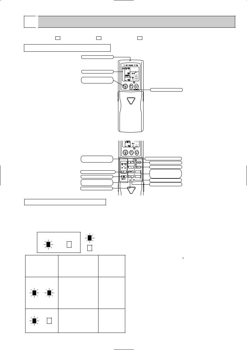
WIRELESS REMOTE CONTROLLER
Signal transmitting section |
|
|
|
Operation display section |
|
|
|
|
|
|
PM |
OPERATE/ STOP |
|
|
AM |
|
|
|
|
(ON/ OFF)button |
ON/OFF |
TOO |
TOO |
|
WARM |
COOL |
|
|
|
TEMPERATURE buttons
CLOCK |
PM |
AM |
ON/OFF |
TOO |
TOO |
|
WARM |
COOL |
VANE button |
|
|
FAN SPEED CONTROL button |
|
(Horizontal vane button) |
FAN |
STOP |
||
OFF-TIMER button |
||||
I FEEL COOL |
|
|
||
|
VANE |
START |
||
|
|
|||
FAN DRY |
|
|
ON-TIMER button |
|
|
|
|
||
MODE |
WIDE VANE |
HR. |
HR. button |
|
OPERATION SELECT button |
|
|
||
|
|
MIN. button |
||
ECONO COOL |
LONG |
MIN. |
||
ECONO COOL button |
|
|
(TIME SET button) |
|
|
RESET CLOCK |
|
CLOCK SET button |
|
WIDE VANE button |
|
|
||
|
|
|
||
(Vertical vane button) |
|
|
LONG button |
RESET button
INDOOR UNIT DISPLAY SECTION
Operation Indicator lamp
The operation indicator at the right side of the indoor unit indicates the operation state.
•The following indication applies regardless of shape of the indicator.
Operation Indicator
lighted
not lighted
Difference between target
Indication Operation state temperature and room temperature
This shows that the air conditioner is operating to reach
the target temperature.
Approx. 2 :
Please wait until the target temperature is obtained.
or more
This shows that the |
|
room temperature is |
Approx. 2 : |
approaching the |
or less |
target temperature. |
|
Once the operation mode are set, the same operation mode can be repeated by simply turning the OPERATE/STOP (ON/OFF) button ON.
Indoor unit receives the signal with a beep tone.
When the system turns off, 3-minute time delay will operate to protect system from overload and compressor will not restart for 3 minutes.
8-1. “I FEEL CONTROL” (  ) OPERATION
(1)Press OPERATE/STOP (ON/OFF) button on the remote controller. OPERATION INDICATOR lamp of the indoor unit turns on with a beep tone.
(2)Select “I FEEL CONTROL” mode with the OPERATION SELECT button.
(3)The operation mode is determined by the room temperature at start-up of the operation.
Initial room temperature |
Mode |
|
|
|
|
25: or more |
COOL mode of |
|
"I FEEL CONTROL" |
||
|
||
|
|
|
more than 13:, |
DRY mode of |
|
less than 25: |
"I FEEL CONTROL" |
9

•Once the mode is fixed, the mode does not change by room temperature afterwards.
•Under the ON-TIMER (  ) operation, mode is determined according to the room temperature at the set time the operation starts.
•When the system is stopped on the remote controller, and restarted within 2 hours in “I FEEL CONTROL” ( 
 ) mode, the system operates in previous mode automatically regardless of the room temperature.
Operation timer chart
Example
Previous operation |
Restart |
|||
COOL mode of |
COOL mode of |
|||
“I FEEL CONTROL” |
“I FEEL CONTROL” |
|||
or COOL mode |
|
|
||
|
|
|
|
|
|
|
|
|
|
When the system is restarted after 2 hours and more, the operation mode is determined by the room temperature at start-up of the operation.
Operation timer chart Example
Previous operation
COOL mode of
“I FEEL CONTROL” or COOL mode
Restart
COOL or DRY mode of “I FEEL CONTROL” that determined by room temperature at start-up of the operation.
(4) The initial set temperature is decided by the initial room temperature.
Model |
Initial room temperature |
Initial set temperature |
||
|
|
|
|
|
COOL mode of |
26: or more |
24: |
1 |
|
"I FEEL CONTROL" |
|
|
||
25: to 26: |
Initial room temperature |
|||
|
|
|||
|
minus 2: |
|
||
|
|
|
||
DRY mode of |
more than 13:, less than 25: |
Initial room temperature |
||
"I FEEL CONTROL" |
minus 2: |
|||
|
||||
1 When the system is restarted with the remote controller, the system operates with the previous set temperature regardless of room temperature at restart.
The set temperature is calculated by the previous set temperature.
(5)TEMPERATURE buttons
In “I FEEL CONTROL” ( 
 ) mode, set temperature is decided by the microprocessor based on the room temperature.
In addition, set temperature can be controlled by TOO WARM or TOO COOL buttons when you feel too cool or too warm. Each time the TOO WARM or TOO COOL button is pressed, the indoor unit receives the signal and emits a beep tone.
• Fuzzy control
When the TOO COOL or TOO WARM button is pressed, the microprocessor changes the set temperature, considering the room temperature, the frequency of pressing TOO COOL or TOO WARM button and the user’s preference to heat or cool. So this is called “Fuzzy control”, and works only in “I FEEL CONTROL” mode.
In DRY mode of “I FEEL CONTROL”, the set temperature doesn’t change.
TOO
COOL
… To raise the set temperature 1~2 degrees(°C)
TOO
WARM
… To lower the set temperature 1~2 degrees(°C)
10
 Loading...