


SPLIT-TYPE AIR CONDITIONERS
INDOOR UNIT
SERVICE MANUAL |
No. OBH536 |
|
Models
MS-C08VC - F1
MS-C10VC - F1
MS-C13VC - F1
Outdoor unit service manual
MU-C·VC Series (OBH537)
CONTENTS
1. TECHNICAL CHANGES ··································· 2
2. PART NAMES AND FUNCTIONS····················· 2
3. SPECIFICATION················································ 3
4. OUTLINES AND DIMENSIONS ························ 3
5. WIRING DIAGRAM············································ 4
6. REFRIGERANT SYSTEM DIAGRAM ··············· 4
7. SERVICE FUNCTIONS ····································· 5
8. MICROPROCESSOR CONTROL ····················· 7
9. TROUBLESHOOTING····································· 12
10. DISASSEMBLY INSTRUCTIONS···················· 21
PARTS CATALOG (OBB536)
NOTE:
RoHS compliant products have <G> mark on the spec name plate.
TM |
1 
 TECHNICAL CHANGES
MS-C08VC - F1
MS-C10VC - F1
MS-C13VC - F1
1. New model
2 
 PART NAMES AND FUNCTIONS
MS-C08VC
MS-C10VC
MS-C13VC
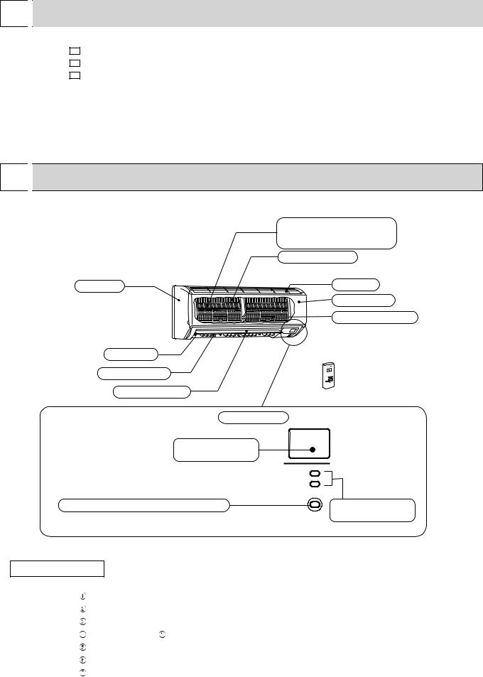
Panel
Air outlet
Vertical vane
Horizontal vane
Air cleaning filter (Option) (Anti-Allergy Enzyme Filter, Blue bellows type)
Heat exchanger
Air inlet
Front panel
Catechin air filter


 Remote controller
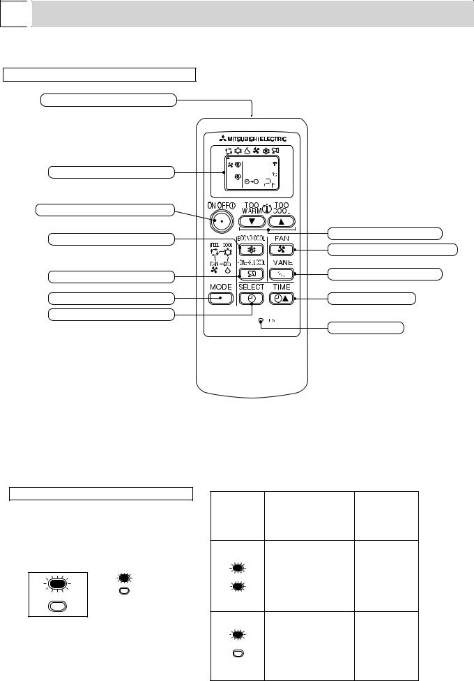
Display section
Remote control receiving section
Emergency operation switch (E.O. SW) |
Operation Indicator |
|
lamp |
ACCESSORIES
|
Installation plate |
1 |
|
Installation plate fixing screw 4 x 25 mm |
5 |
|
Remote controller holder |
1 |
|
Fixing screw for 3.5 x 1.6 mm (Black) |
2 |
|
Battery (AAA) for remote controller |
2 |
|
Wireless remote controller |
1 |
|
|
|
|
Felt tape (Used for left or left-rear piping) |
1 |
|
|
|
2

3 
 SPECIFICATION
Indoor model
Function
Power supply
Electrical data |
Breaker capacity |
|
Power input |
||
|
Running current |
|
Fan motor |
Model |
|
Fan motor current |
||
Dimensions W H D |
||
Weight |
Air direction |
|
Special remarks |
||
Air flow (High/Med./Low) |
||
Fan speed (High/Med./Low) |
||
|
Sound level (High/Med./Low) |
|
|
Fan speed regulator |
|
Remote controller model
|
MS-C08VC |
|
MS-C10VC |
MS-C13VC |
|
|
|
Cooling |
|
|
|
|
|
|
|
|
|
Single phase |
|
A |
|
|
220-230-240 V, 50 Hz |
|
|
10 |
|
||
A |
|
0.22 |
|
|
W |
|
45 |
|
|
A |
|
|
RC4V18-BA |
|
|
0.22 |
|
||
mm |
|
788 295 225 |
|
|
kg |
|
9 |
|
|
m3/h |
558/420/288 |
4 |
|
|
|
618/456/288 |
624/480/330 |
||
dB |
39/32/26 |
|
40/33/26 |
42/36/29 |
rpm |
1,000/800/600 |
|
1,090/850/600 |
1,100/880/660 |
|
|
|
3 |
|
|
|
|
MP07A |
|
NOTE : Test conditions are based on ISO 5151. |
|
|
Cooling : Indoor Dry-bulb temperature 27 |
°C |
Wet-bulb temperature 19 °C |
Outdoor Dry-bulb temperature 35 |
°C |
Wet-bulb temperature 24 °C |
Indoor outdoor piping length : 5 m |
|
|
4 
 OUTLINES AND DIMENSIONS
MS-C08VC MS-C10VC MS-C13VC
5 225
58
42
57
140
|
|
|
|
|
Unit : mm |
||
11X26 Oblong hole |
|
|
11X20 Oblong hole |
||||
Installation plate |
59 |
225 |
225 |
59 |
|
18.5 |
|
|
|
|
|
|
|||
788 |
|
|
|
|
|
|
|
254.5 |
215 |
|
|
|
214 |
|
235 253.5 |
|
40.5 |
|
155 |
155 |
2 |
41.5 |
|
|
59 |
335 |
320 |
|
|||
Indoor unit |
74 |
|
|
||||
|
|
|
Wall hole |
Φ65 |
|||
|
|
|
Air in |
|
|||
|
|
|
|
|
|
|
|
|
|
|
|
Installation plate |
|
|
|
|
|
|
|
|
Piping |
|
|
295 |
|
|
|
|
|
|
|
|
|
|
|
8 |
|
|
|
|
|
|
|
100 |
42 |
57 |
Drain hose |
|
|
|
|
119 |
|
||
53 |
607 |
128 |
|
|
|
|
|
|
|
137 |
|
|
|||
|
|
|
|
|
Air out |
|
|
17.5 |
|
|
|
|
|
|
|
42 |
|
42 |
Piping |
Insulation |
Φ35 O.D |
|
|
|
Gas line |
MS-C08/C10VC Φ9.52 - 0.43m (Flared connection Φ9.52) |
|||||
|
|
|
|
Liquid line |
Φ6.35 - 0.5m (Flared connection Φ6.35) |
||
|
58 |
50 |
|
|
MS-C13VC Φ12.7- 0.43m (Flared connection Φ12.7) |
||
|
|
|
|
Drain hose |
Insulation Φ28 Connected part Φ16 O.D |
||
3
5 
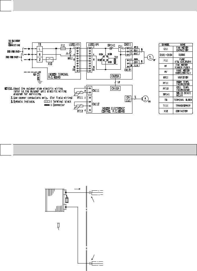
 WIRING DIAGRAM
MS-C08VC
MS-C10VC
MS-C13VC
6 
 REFRIGERANT SYSTEM DIAGRAM
MS-C08VC MS-C10VC MS-C13VC
Unit : mm
Refrigerant pipe Φ9.52 (MS-C08/C10VC) Φ12.7 (MS-C13VC)
(with heat insulator)
Indoor |
Indoor coil |
|
|
thermistor |
|
||
heat |
RT12 |
|
|
exchanger |
Flared connection |
||
|
Room temperature thermistor
RT11
Flared connection
Refrigerant pipe Φ6.35 (with heat insulator)
 Refrigerant flow in cooling
4
7 
 SERVICE FUNCTIONS
MS-C08VC
MS-C10VC
MS-C13VC
7-1. TIMER SHORT MODE
For service, set time can be shortened by short circuit of JPG and JPS on the electronic control P.C. board. The time will be shortened as follows: (Refer to 9-7.)
Set time : 1-minute → 1-second
Set time : 3-minute → 3-second (It takes 3 minutes for the compressor to start operation. However, the starting time is shortened by short circuit-of JPG and JPS.)
7-2. P.C. BOARD MODIFICATION FOR INDIVIDUAL OPERATION
A maximum of 4 indoor units with wireless remote controllers can be used in a room.
In this case, to operate each indoor unit individually by each remote controller, P.C. boards of remote controller must be modified according to the number of the indoor unit.
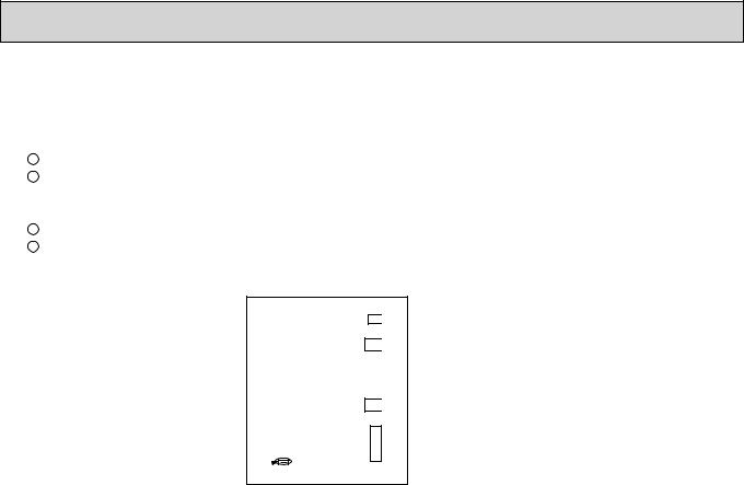
How to modify the remote controller P.C. board
Remove batteries before modification.
The board has a print as shown below :
J1 J2
NOTE : For modification, take out the batteries and press the OPERATE/STOP(ON/ OFF)button twice or 3 times at first.
After modification, put back the batteries then press the RESET button.
The P.C. board has the print “J1” and “J2”. Solder “J1” and “J2” according to the number of indoor unit as shown in Table 1. After modification, press the RESET button.
Table 1
|
1 unit operation |
2 units operation |
3 units operation |
4 units operation |
|
|
|
|
|
No. 1 unit |
No modification |
Same as at left |
Same as at left |
Same as at left |
|
|
|
|
|
No. 2 unit |
– |
Solder J1 |
Same as at left |
Same as at left |
|
|
|
|
|
No. 3 unit |
– |
– |
Solder J2 |
Same as at left |
|
|
|
|
|
No. 4 unit |
– |
– |
– |
Solder both J1 and J2 |
|
|
|
|
|
How to set the remote controller exclusively for particular indoor unit
After you turn the breaker on, the first remote controller that sends the signal to the indoor unit will be regarded as the remote controller for the indoor unit.
The indoor unit will only accept the signal from the remote controller that has been assigned to the indoor unit once they are set.
The setting will be cancelled if the breaker has turned off, or the power supply has shut down. Please conduct the above setting once again after the power has restored.
5
7-3. AUTO RESTART FUNCTION
When the indoor unit is controlled with the remote controller, the operation mode, the set temperature, and the fan speed are memorized by the indoor electronic control P.C. board. The “AUTO RESTART FUNCTION” sets to work the moment power has restored after power failure. Then, the unit will restart automatically.
Operation
1When the main power is cut off, the operation settings remain.
2After the power is restored, the unit restarts automatically according to the memory. (However, it takes at least 3 minutes for the compressor to start running.)
How to release “AUTO RESTART FUNCTION”
1Turn off the main power for the unit.
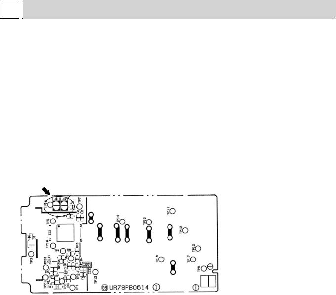
2Solder the Jumper wire to JR07 on the indoor electronic control P.C. board. (Refer to 9-7.)
MS-C08/C10/C13VC
Indoor electronic control P.C. board
JR07

 CN10A CN151 CN112 CN111
NOTE:
•The operation settings are memorized when 10 seconds have passed after the indoor unit was operated with the remote controller.
•If main power is turned off or a power failure occurs while AUTO START/STOP timer is active, the timer setting is cancelled.
•If the unit has been off with the remote controller before power failure, the auto restart function does not work as the power button of the remote controller is off.
•To prevent breaker off due to the rush of starting current, systematize other home appliance not to turn on at the same time.
•When some air conditioners are connected to the same supply system, if they are operated before power failure, the starting current of all the compressors may flow simultaneously at restart.
Therefore, the special counter-measures are required to prevent the main voltage-drop or the rush of the starting current by adding to the system that allows the units to start one by one.
6
8 
 MICROPROCESSOR CONTROL
MS-C08VC MS-C10VC MS-C13VC
WIRELESS REMOTE CONTROLLER
Signal transmitting section
Operation display section |
|
OPERATE/STOP (ON/OFF) button |
|
ECONO COOL button |
TEMPERATURE buttons |
|
|
|
FAN SPEED CONTROL button |
POWERFUL COOL button |
VANE CONTROL button |
OPERATION SELECT button |
TIME SET button |
TIMER MODE SELECT button |
|
|
RESET button |
NOTE: • Last setting will be stored after the unit is turned OFF with the remote controller.
• Indoor unit receives the signal of the remote controller with beeps.
INDOOR UNIT DISPLAY SECTION |
|
|
Difference |
|
Operation Indicator lamp |
|
|
between target |
|
Indication |
Operation state |
temperature |
||
The operation indicator at the right side of the indoor |
||||
|
|
and room |
||
unit indicates the operation state. |
|
|
temperature |
|
Operation Indicator |
|
This shows that the |
|
|
|
|
air conditioner is |
|
|
|
|
operating to reach |
Approx. 2°C |
|
Lighted |
|
the target temperature. |
||
|
or more |
|||
Not lighted |
|
Please wait until the |
|
|
|
target temperature is |
|
||
|
|
obtained. |
|
|
|
|
This shows that the |
|
|
|
|
room temperature is |
Approx. 2°C |
|
|
|
approaching the |
||
|
|
or less |
||
|
|
target temperature. |
||
|
|
|
7
8-1. COOL ( ) OPERATION
(1)Press OPERATE/STOP(ON/OFF) button.
OPERATION INDICATOR lamp of the indoor unit turns on with a beep tone.
(2)Select COOL mode with OPERATION SELECT button.
(3)Set TEMPERATURE buttons.
Press TOO WARM or TOO COOL button to select the desired temperature. The setting range is 16 ~ 31°C.
1. Coil frost prevention
When the temperature of indoor heat exchanger becomes too low, the coil frost prevention mode works. The indoor fan operates at the set speed and the compressor stops.
This mode continues until the temperature of indoor heat exchanger rises.
8-2. DRY ( )OPERATION
(1)Press OPERATE/STOP(ON/OFF) button.
OPERATION INDICATOR lamp of the indoor unit turns on with a beep tone.
(2)Select DRY mode with OPERATION SELECT button.
(3)The set temperature is determined from the initial temperature.
1. Coil frost prevention
• The operation is the same as coil frost prevention during COOL mode.
8-3. FAN ( )OPERATION
(1)Press OPERATE/STOP(ON/OFF) button. OPERATION INDICATOR lamp of the indoor unit turns on with a beep tone.
(2)Select FAN mode with OPERATION SELECT button.
(3)Select the desired fan speed. When AUTO, it becomes Low. Only indoor fan operates.
Outdoor unit does not operate.
8-4. “I FEEL CONTROL” (
 ) OPERATION
(1)Press OPERATE/STOP(ON/OFF) button on the remote controller. OPERATION INDICATOR lamp of the indoor unit turns on with a beep tone.
(2)Select “I FEEL CONTROL”(
 ) mode with the OPERATION SELECT button.
(3)The operation mode is determined by the initial room temperature at start-up of the operation.
Initial room temperature |
Mode |
|
|
|
|
25°C or more |
COOL mode of |
|
“I FEEL CONTROL” |
||
|
||
more than 13°C, |
DRY mode of |
|
less than 25°C |
“I FEEL CONTROL” |
|
|
|
•Once the mode is fixed, the mode is not changed by room temperature afterwards.
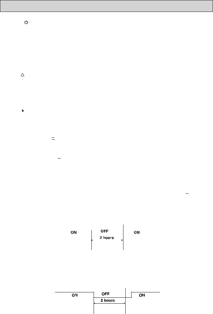
•Under ON-TIMER ( ) operation, the mode is determined as follows:
When the system is stopped by the remote controller and restarted within 2 hours in “I FEEL CONTROL” ( 
 ) mode, the system operates in previous mode automatically regardless of the room temperature.
Operation time chart
Example
Previous operation |
|
|
Restart |
|
|
|
COOL mode of |
||
COOL mode of |
|
|
||
|
|
“I FEEL CONTROL” |
||
“I FEEL CONTROL” |
|
|
||
|
|
|
|
|
or COOL mode |
|
|
|
|
|
|
|
|
|
|
|
|
|
|
When the system is restarted after 2 hours and more, the operation mode is determined by the room temperature at start-up of the operation.
Operation time chart Example
Previous operation
COOL mode of
“I FEEL CONTROL” or COOL mode
Restart
COOL or DRY mode of “I FEEL CONTROL” that determined by room temperature at start-up of the operation.
8
 Loading...