


MSC-07RV
Mitsubishi MSC-07RV, MU-07RV, MSC-09RV, MU-09RV, MSC-12RV SERVICE MANUAL
...
SPLIT-TYPE, AIR CONDITIONERS
SPLIT-TYPE, HEAT PUMP AIR CONDITION
NOTE: • This service Manual covers only change points.
SERVICE MANUAL
Wireless type
Models
MSC-07RV MSC-09RV MSC-12RV -
MSC-07RV MSC-09RV MSC-12RV -
MSC-07RV MSC-09RV MSC-12RV -
MSC-07RV MSC-09RV MSC-12RV -
MSC-07RV MSC-09RV MSC-12RV -
MSC-07RV MSC-09RV MSC-12RV -
Multi system type
MSC-07RV MSC-09RV MSC-12RV -
Inverter controlled multi system type
(WH)
(WH)
(WH)
(WH)
(WH)
(WH)
(WH)
(WH)
(WH)
(WH)
(WH)
(WH)
(WH)
(WH)
(WH)
(WH)
(WH)
(WH)
(WH)
(WH)
(WH)
· MU-07RV -
· MU-09RV -
· MU-12RV -
· MU-07RV -
· MU-09RV -
· MU-12RV -
· MU-07RV -
· MU-09RV -
· MU-12RV -
· MUH-07RV -
· MUH-09RV -
· MUH-12RV -
· MUH-07RV -
· MUH-09RV -
· MUH-12RV -
· MUH-07RV -
· MUH-09RV -
· MUH-12RV -
· MUX-10RV -
· MUX-18RV -
· MUX-24RV -
· MXZ-18RV -
Please refer to the Service Manual OB227 REVISED
EDITION-B for unchanged contents.
• Please refer to the following service manual when the
outdoor unit is the under mentioned model.
MXZ-32SV- : OB254
MXZ-18TV- : OB280
MUX-19/20/25TV- : OB284
• Please void OB252 REVISED EDITION-B.
E1
E1
E1
No. OB252
REVISED EDITION-C
E2E2
E2E2
E2E2
E3E3
E3E3
E3E3
E4E4
E4E4
E4E4
E2E2
E2E2
E2E2
E3E3
E3E3
E3E3
E4E4
E4E4
E4E4
E2E2
E2E2
E2E2
E2
MSC-07RV MSC-09RV MSC-12RV -
E4
E4
E4
CONTENTS
1. TECHNICAL CHANGES ····································3
2. PART NAMES AND FUNCTIONS······················8
3. SPECIFICATION···············································11
4. WIRING DIAGRAM ··········································13
5. REFRIGERANT SYSTEM DIAGRAM··············15
6. MICROPROCESSOR CONTROL ····················16
7. TROUBLESHOOTING······································16
8. PARTS LIST ·····················································27
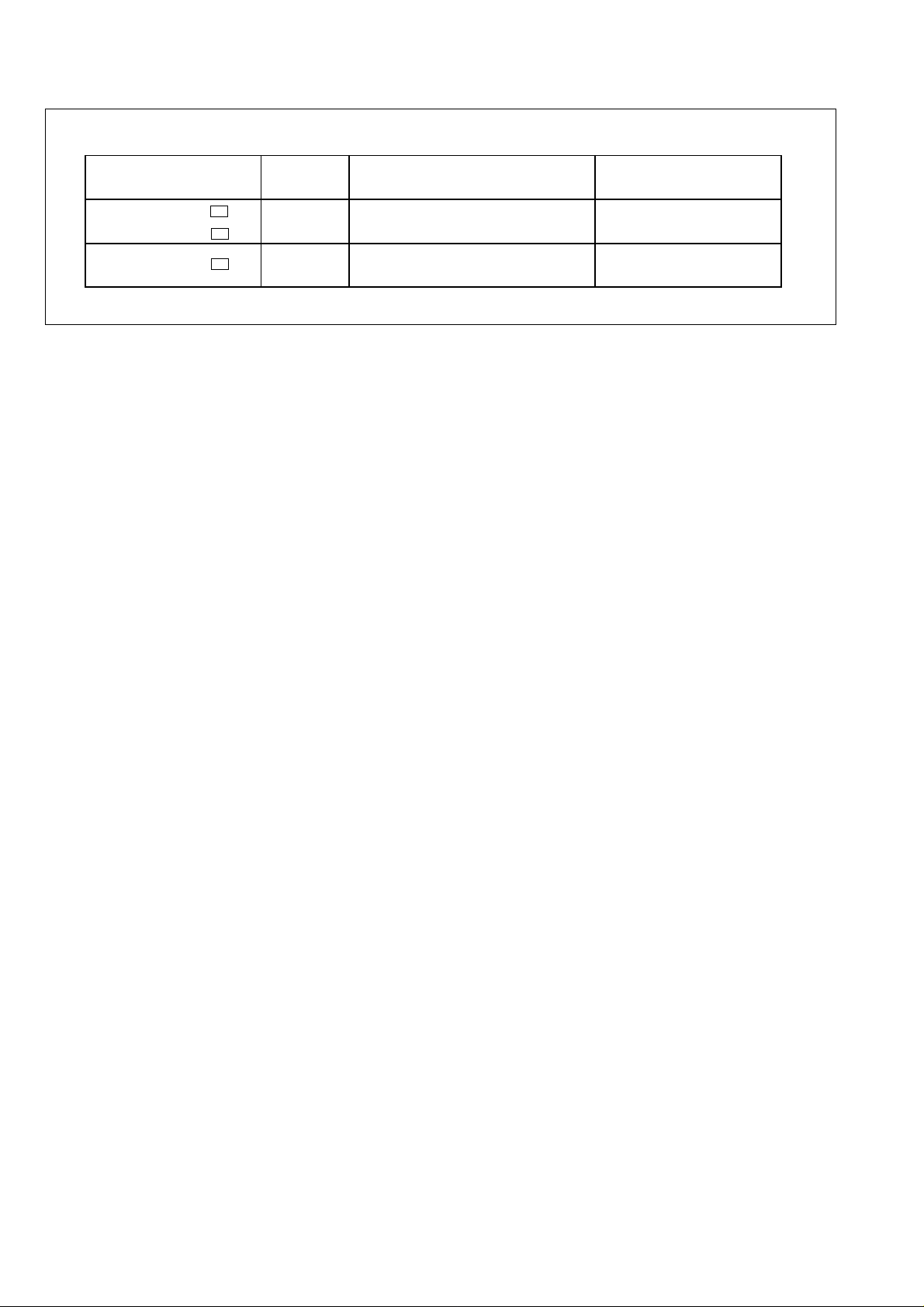
REVISION
Page
Part name
E02 504 426 ➔ E02 141 083 REMOTE CONTROLLER HOLDER
Model
MSC-07/09/12RV-
E1
MSC-07/09/12RV-
E2
MSC-07/09/12RV-
E2
P27
Part number
P27 REMOTE CONTROLLER
E02 141 083 ➔ E02 504 426
Parts numbers have been partially modified.
1
1
2
3
4
5
6
7
8
9
10
11
12
13
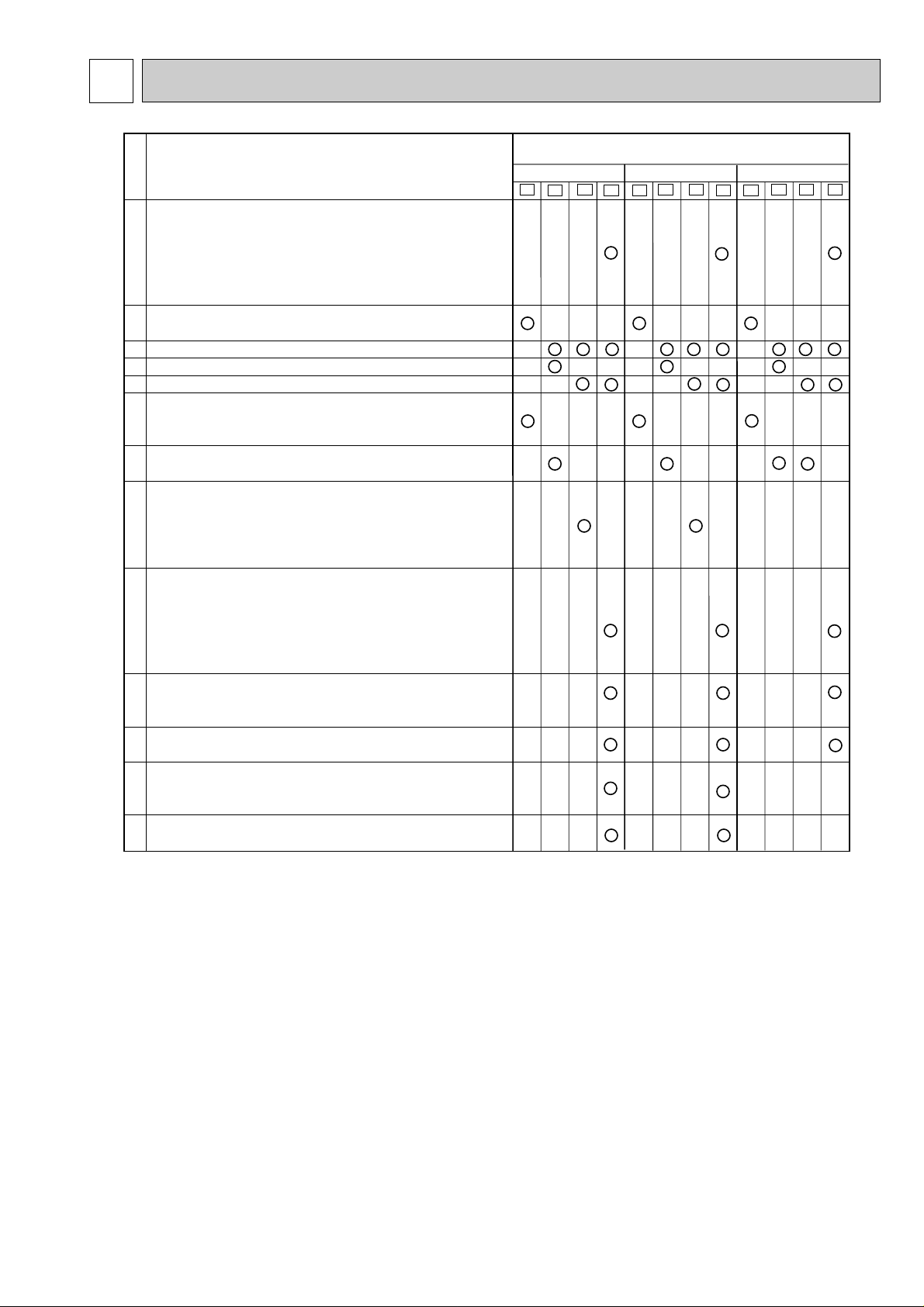
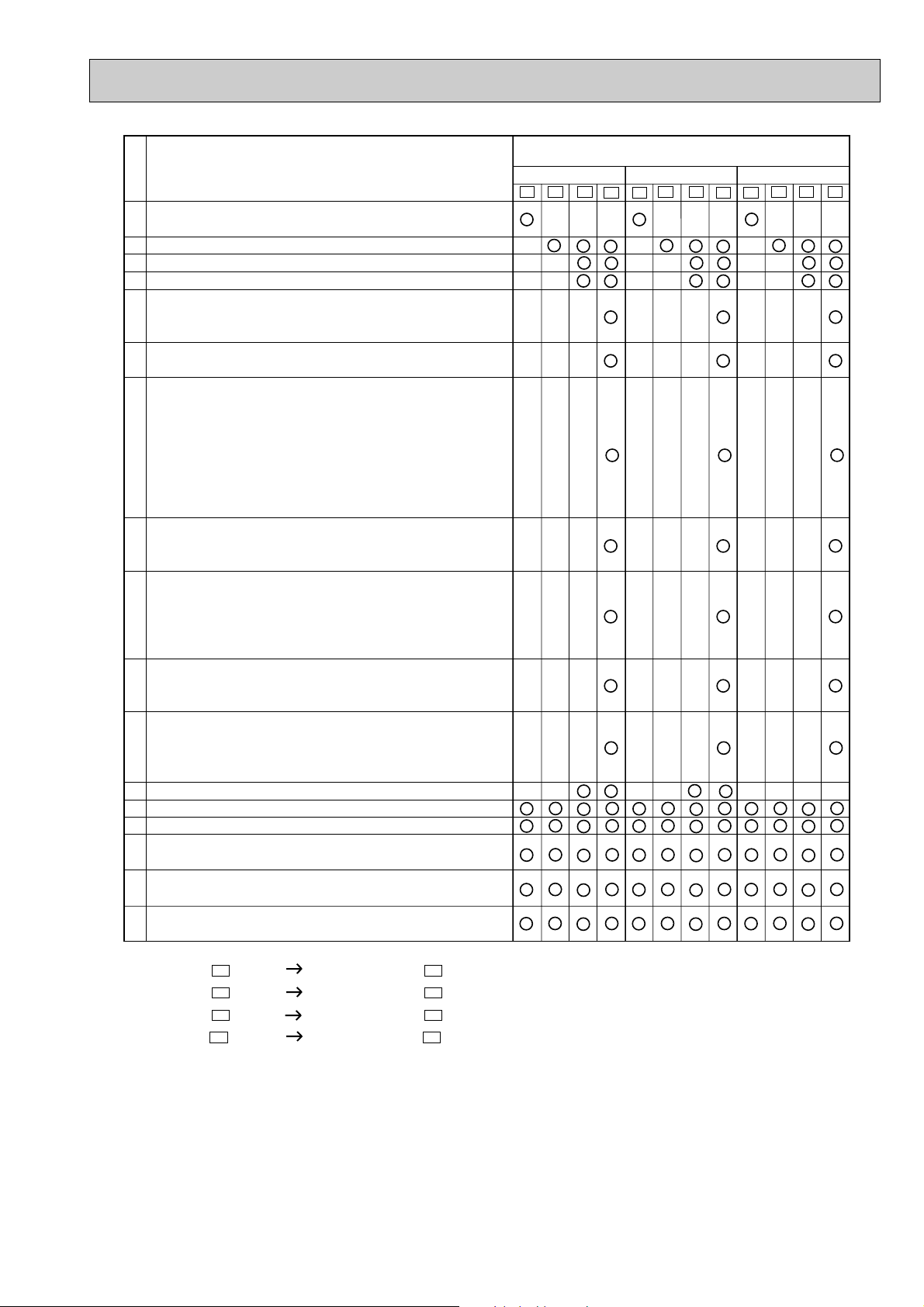
The specifications of Indoor and Outdoor fan motor.
The data of Med. and Low speed are added to Indoor fan motor
specification
✼
✼The data value of indoor fan motor does not change if the indoor
unit is connected to a multi-type outdoor unit.
Remote controllers of COOL ONLY or COOL & HEAT
type are outdoor unit accessory.
Remote controller is included as an indoor unit accessory.
Two-way common remote controller
Two-way (using dip switch) remote controller
The specification of electronic control P.C. board is
compatible with remote controllers of COOL ONLY
and COOL & HEAT type.
Indoor electronic control P.C. board has changed
for two-way remote controller.
Indoor electronic control P.C. board has changed
for two-way remote controller.
Microprocessor programing flow has changed.
Electronic control P.C. board for E3 is interchangeable
with the one for E2 (except for MSC-12RV).
(New P.C. board) Indoor electronic control P.C. board has
changed.
Earth wire from the board is fixed to the electrical box with screw.
The shape of connector CN211 has changed. Indoor electronic
control P.C. board has been connected with
Power monitor, receiver P.C. board using connector.
When fan speed is set to"Auto", initial temperature difference
specitying changing fan speed has been improved in order to
reach the set temperature faster than E1, E2, and E3.
The mark of terminal block has changed. Terminal block for E4 is
interchangeable with the ones for E1, E2 and E3.
Winding resistance and shape of fan motor have changed.
Fan motor for E4 is not interchangeable with the ones for E1,
E2 and E3 except for MSC-12RV.
Fan motor rubber mount has changed because the shape of
fan motor was changed.
Circle shows the change point of the model.
Change point
No.
MSC-07RV-
E1
E2
E3
MSC-09RV-
E1
E2
E3
MSC-12RV-
E1
E2
E3
E4
E4
E4
TECHNICAL CHANGES
3
1
2
3
4
5
6
7
8
9
10
11
12
13
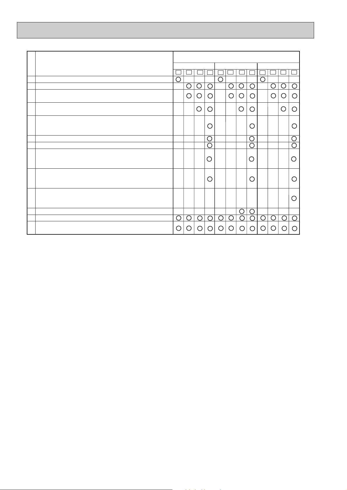
Remote controller of COOL ONLY type is outdoor unit accessory.
Remote controller is included as an indoor unit accessory.
Compressor contactor (52C) has changed. Compressor
contactor for E2,E3,E4 are interchangeable with the ones for E1.
Compressor has changed. Compressors for E3 and E4 are not
interchangeable with the ones for E1 and E2.
Compressor capacitor has changed. Due to different shape,
compressor capacitor for E4 is not interchangeable with the
ones for E1, E2 and E3.
Fuse has been removed.
Wiring diagram has changed because fuse was removed.
The shape of propeller fan has changed. The number of
propeller fan has changed from four to three. Propeller fan for E4
is not interchangeable with the ones for E1, E2 and E3.
The shape, diameter of axis and fan speed of fan motor have
changed. Fan motor for E4 is not interchangeable with the ones
for E1, E2 and E3.
Fan motor capacitor has changed. 1.5+➔ 2.0+
Fan motor capacitor for E4 is not interchangeable with the
ones for E1, E2 and E3(MU-12RV only).
Refrigerant filing capacity has changed. 0.85kg➔ 0.80kg
The method of troubleshooting for outdoor unit has changed.
The repairing procedure when outdoor unit does not stop
has been added to troubleshooting.
Circle shows that change points apply to the models.
Change point
No.
MU-07RV-
E1
E2
E3
MU-09RV-
E1
E2
E3
MU-12RV-
E1
E2
E3
E4
E4
E4
4
No.
Remote controller of COOL & HEAT type is outdoor unit
1
accessory.
Remote controller is included as an indoor unit accessory.
2
Accumulator has been removed.
3
Compressor has changed.
4
Compressor capacitor has changed. Due to different
shape, compressor capacitor for E4 is not interchangeable
5
with the ones for E1,E2 and E3.
The mark of terminal block has changed. Terminal block
6
for E4 is interchangeable with the ones for E1, E2 and E3.
Deicer P.C. board has changed. Jumper wire of compulsory
defrosting mode has changed.
Jumper wire for defrost setting has changed.
(JPC-JPE➔JRF-JRG) (Refer to page 26.)
7
The defrosting intervals which are changed by setting a short
circuit are the same as E1, E2, and E3.
Deicer P.C. board for E4 is not interchangeable with the
ones for E1, E2 and E3.
Wiring diagram has changed according to the following
reasons; the shape of connectors CN711 and CN661 has
8
changed and R.V. coil relay (X62) has changed into SSR (SR62).
X62 has changed into SR62 in Example of Operation
time chart in HEAT operation.
9
Compared to E1, E2, and E3, no change has been made about
the operational condition for defrosting and tne control system of
R.V. coil (timing of switching on/off).
The shape of propeller fan has changed. The number of
propeller fan has changed from four to three. Propeller
10
fan for E4 is not interchangeable with the ones for E1,E2, and E3.
The shape and diameter of axis of fan motor have changed.
The shape of connector has changed.
11
Fan motor and connector for E4 are not interchangeable
with those for E1, E2 and E3.
Refrigerant filling capacity has changed. 0.80kg➔ 0.85kg
12
The method of checking serial signal error for E4 has been added.
13
The method of troubleshooting for outdoor unit has changed.
14
The method for checking thermistor has been added to
15
troubleshooting.
The method for checking 4-way valve has been added to
16
troubleshooting.
The repairing procedure when outdoor unit does not stop has
17
been added to troubleshooting.
Change point
(JP607-R853➔JPDS-JPSG)
Circle shows that change points apply to the models.
MUH-07RV-
E1
E2
E3
E4
MUH-09RV-
E1
E2
E3
E4
MUH-12RV-
E1
E2
E3
E4
MUX-10RV MUX-18RV MUX-24RV MXZ-18RV -
E1
E1
E1
E1
MUX-10RV MUX-18RV MUX-24RV MXZ-18RV -
E2
E2
E2
E2
1. Remote controller is unprovided as the outdoor unit accessory.
5
COOL ONLY
COOL
& HEAT
TWO-WAY
REMOTE CONTROLLER
Model
MS-07/09/12RV-
E1
MSH-07/09/12RV-
E1
MS-07/09/12RV-
E2
MSH-07/09/12RV-
E2
✕
✕
✕
✕
w
w When HEAT mode is selected
by the remote controller of
COOL & HEAT type, the unit
will operate in FAN mode.
TWO-WAY
DIP switch
✕
MS-07/09/12RV-
E3
MSH-07/09/12RV-
E3
MS-07/09/12RV-
E4
MSH-07/09/12RV-
E4
✕
✕
Reference
162
19
58
Wireless remote controller
MSC-07RV MSC-09RV MSC-12RV MU-07RV MU-09RV MU-12RV MUH-07RV MUH-09RV MUH-12RV -
E1
E1
E1
E1
E1
E1
E1
E1
E1
MSC-07RV MSC-09RV MSC-12RV MU-07RV MU-09RV MU-12RV MUH-07RV MUH-09RV MUH-12RV -
E2
E2
E2
E2
E2
E2
E2
E2
E2
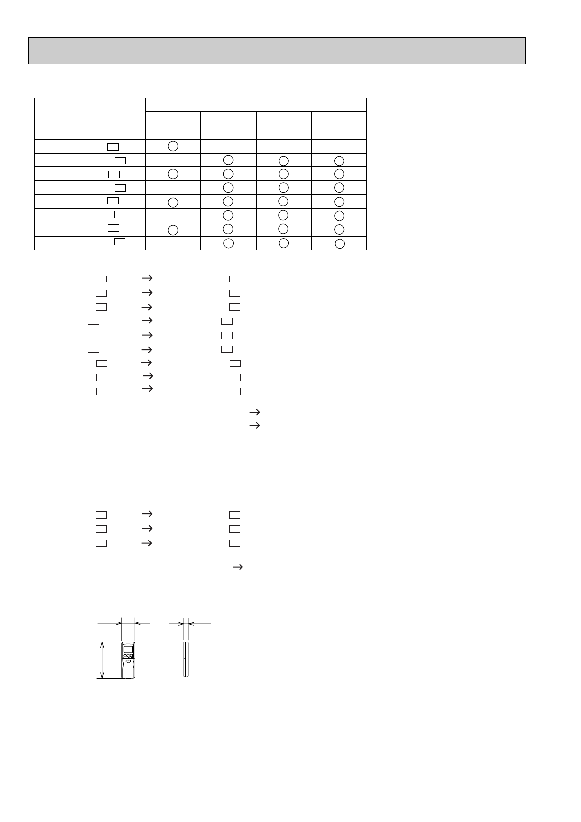
COOL ONLY REMOTE CONTROLLER TWO-WAY REMOTE CONTROLLER
COOL&HEAT REMOTE CONTROLLER TWO-WAY REMOTE CONTROLLER
1. Both of COOL ONLY and COOL & HEAT remote controller are unified into a two-way remote controller.
2. FAN mode operation is available in COOL ONLY unit. In this case the set room temperature
will be displayed on the remote controller, however, the room temperature can not be controlled by remote controller button.
HEAT operation is available in only HEAT & COOL type unit.
MSC-07RV MSC-09RV MSC-12RV -
E2
E2
E2
MSC-07RV MSC-09RV MSC-12RV -
E3
E3
E3
TWO-WAY REMOTE CONTROLLER TWO-WAY DIP SWITCH REMOTE CONTROLLER
• Outlines and dimensions have been changed.
6
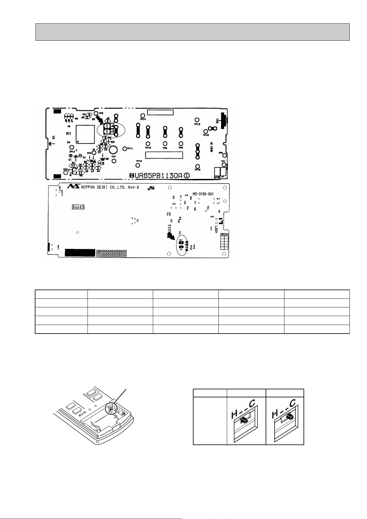
• The way of remodelling individual operation of P.C Board of remote controller has changed.
No. 1 unit
No. 2 unit
No. 3 unit
No. 4 unit
1 unit operation
No modification
–
–
–
2 units operation
Same as at left
Solder J1
–
–
3 units operation
Same as at left
Same as at left
Solder J2
–
4 units operation
Same as at left
Same as at left
Same as at left
Solder both J1 and J2
A maximum of 4 indoor units with wireless remote controllers can be used in a room.
In this case, to operate each indoor unit individually by each remote controller, P.C. boards of remote controller must be
modified according to the number of the indoor unit.
How to modify the remote controller P.C. board
Remove batteries before modification.
The board has a print as shown below :
NOTE : For remodelling, take out the bat-
teries and press the
OPERATE/STOP(ON/OFF)button
twice or 3 times at first.
After finish remodelling, put back
the batteries then press the
RESET button.
The P.C. board has the print “J1” and “J2”. Solder “J1” and “J2” according to the number of indoor unit as shown
in Table 1. After modification, press the RESET button.
Table 1
REMOTE CONTROLLER (How to set the type)
This remote controller setting needs to be switched according to the type of air conditioner (COOL & HEAT or COOL
ONLY).
If the setting is incorrect, the air conditioner does not operate normally. Therefore, check if the setting corresponds to
the type of air conditioner. If it does not, correct the setting as shown below.
Slide switch
Type
The position
of the slide
switch
COOL ONLYCOOL & HEAT
7

Installation plate
Installation plate fixing screw 4 o 25 mm
Remote controller mounting hardware
Fixing screw for 3 3.5 o 16 mm
Battery (AAA) for remote controller
Felt tape (Used for left or left-rear piping)
Deodorizing filter
Air cleaning filter
Wireless remote controller
Drain socket: MUH type
Drain cap: MUH type
1
1
2
1
5
1
2
2
1
1
1
<Indoor unit>
Installation plate
Installation plate fixing screw 4 o 25 mm
Remote controller mounting hardware
Fixing screw for 3 3.5 o 16 mm
Battery (AAA) for remote controller
Wireless remote controller
Felt tape (Used for left or left-rear piping)
Deodorizing filter
Air cleaning filter
Drain socket
Drain cap
1
2
1
5
1
2
2
1
1
1
1
<Indoor unit>
<Outdoor unit: MUH type><Outdoor unit>
9
0
1
1
2
3
4
5
6
7
8
0
1
1
2
3
4
5
6
7
8
9
• How to replace batteries
Insert the negative pole
of the batteries first.
Check if the polarity of
the batteries are correct.
HEAT
/FAN
/
RESET button
HEAT
/FAN
/
Weak batteries may cause the remote controller malfunction.
In this case, replace the batteries to operate the remote controller normally.
1 Remove the front lid and insert batteries.
2 Press the RESET button.
Then re-attach the front lid.
NOTE : If the RESET button is not pressed, the remote controller may not operate correctly.
2
PART NAMES AND FUNCTIONS
ACCESSORIES
MSC-07RV - • MU-07RV MSC-09RV - • MU-09RV MSC-12RV - • MU-12RV MSC-07RV - • MUH-07RV MSC-09RV - • MUH-09RV MSC-12RV - • MUH-12RV -
MSC-07RV - • MU-07RV MSC-09RV - • MU-09RV MSC-12RV - • MU-12RV MSC-07RV - • MUH-07RV MSC-09RV - • MUH-09RV MSC-12RV - • MUH-12RV MSC-07RV - • MU-07RV MSC-09RV - • MU-09RV MSC-12RV - • MU-12RV MSC-07RV - • MUH-07RV MSC-09RV - • MUH-09RV -
E1E1
E1E1
E1E1
E1E1
E1E1
E1E1
MSC-12RV - • MUH-12RV MSC-07RV - • MU-07RV MSC-09RV - • MU-09RV MSC-12RV - • MU-12RV MSC-07RV - • MUH-07RV MSC-09RV - • MUH-09RV MSC-12RV - • MUH-12RV -
E2E2
E2E2
E2E2
E2E2
E2E2
E2E2
E3E3
E3E3
E3E3
E3E3
E3E3
E3E3
E4E4
E4E4
E4E4
E4E4
E4E4
E4E4
8
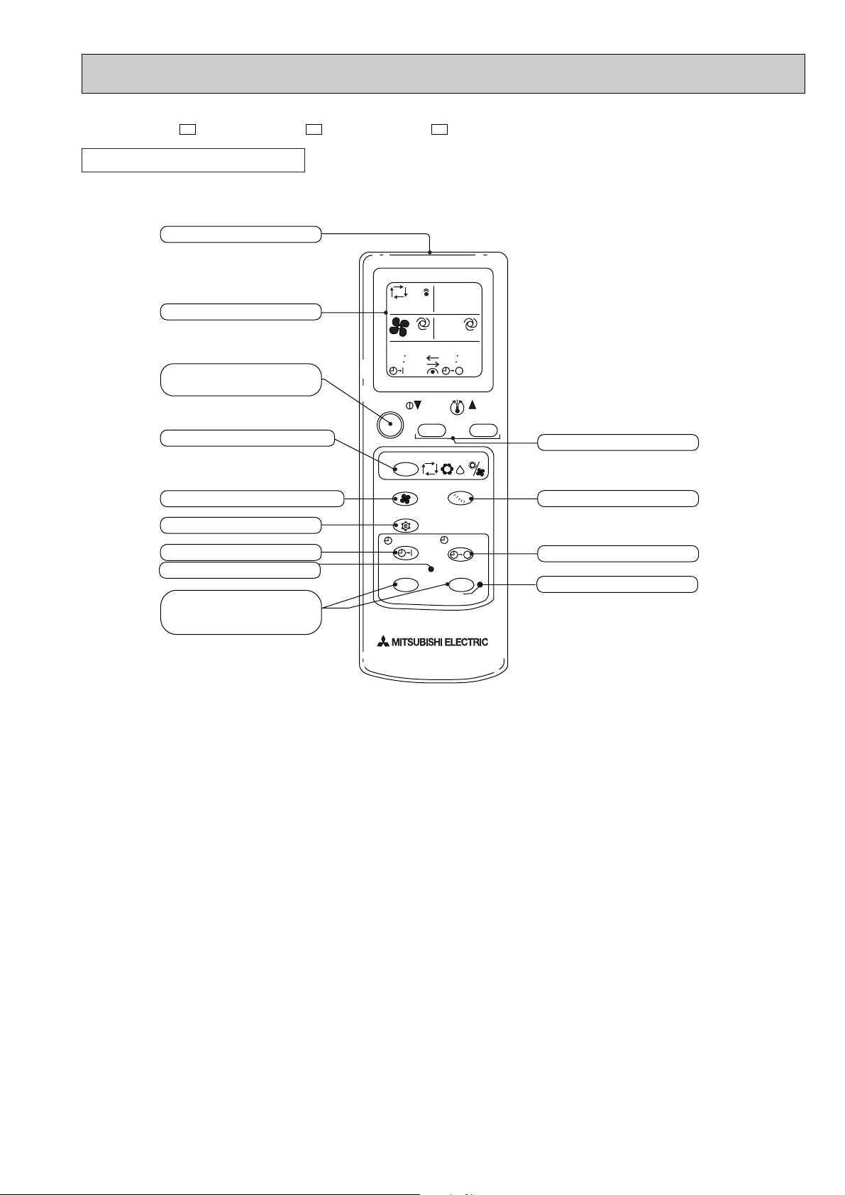
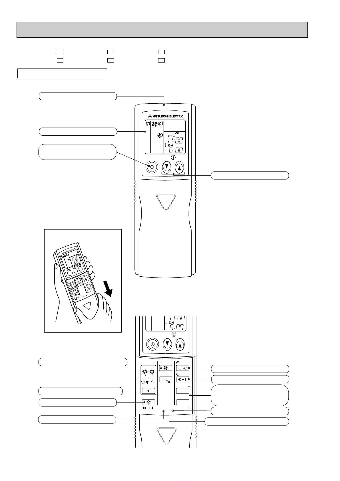
MSC-07RV - MSC-09RV - MSC-12RV -
Signal transmitting section
Operation display section
OPERATE /STOP
(ON /OFF)button
OPERATION SELECT button
FAN SPEED CONTROL button
ON-TIMER button
CLOCK SET button
HR. button
MIN. button
(TIME SET button)
TEMPERATURE buttons
VANE CONTROL button
OFF-TIMER button
RESET button
ON/OFF TOO
WARM
TOO
COOL
HR. MIN.
CLOCK
RESET
CLOCK
MODE
FAN
VANE
START
STOP
ECONO COOL button
ECONO COOL
I FEEL
COOL DRY
HEAT/FAN
6 00 1
1 00
AM
PM
REMOTE CONTROLLER
E2E2E2
9
MSC-07RV - MSC-09RV - MSC-12RV MSC-07RV - MSC-09RV - MSC-12RV -
REMOTE CONTROLLER
Signal transmitting section
E3E3E3
E4E4E4
Operation display section
OPERATE /STOP
(ON /OFF)button
Open the front lid.
ON/OFF
TOO
WARM
PM
AM
TOO
COOL
TEMPERATURE buttons
FAN SPEED CONTROL button
OPERATION SELECT button
ECONO COOL button
RESET button
TOO
ON/OFF
WARM
COOL
DRY
FAN
VANE
RESET
I FEEL
HEAT
/FAN
/
MODE
ECONO COOL
10
CLOCK
CLOCK
PM
AM
TOO
COOL
STOP
START
HR.
MIN.
OFF-TIMER button
ON-TIMER button
HR. button
MIN. button
(TIME SET button)
CLOCK SET button
VANE CONTROL button
3
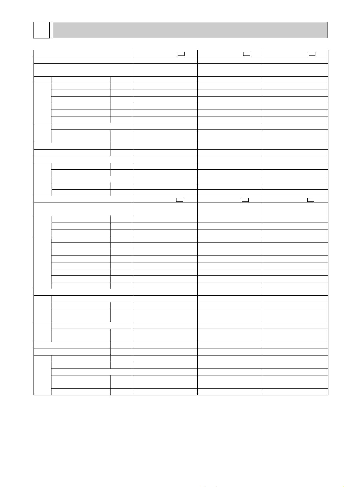
Indoor model
Function
Indoor unit power supply
Air flow(High/Med. /Low )
Power outlet
Running current
Power input
Power factor
Starting current
Fan motor current
Model
Winding
resistance(at20:)
Dimensions WOHOD
Weight
Air direction
Sound level(High/Med. /Low )
Fan speed (High/Med. /Low )
Fan speed regulator
Thermistor RT11(at25:)
Thermistor RT12(at25:)
Outdoor model
Capacity
Dehumidification
Outdoor air flow
Power outlet
Running current
Power input
Auxiliary heater
Power factor
Starting current
Compressor motor current
Fan motor current
Model
Output
Winding
resistance(at20:)
Model
Winding
resistance(at20:)
Dimensions WOHOD
Weight
Sound level
Fan speed
Fan speed regulator
Refrigerant filling
capacity(R22)
Refrigerating oil (Model)
K /h
A
A
W
%
A
A
"
mm
kg
dB
rpm
k"
k"
kW
R/h
K /h
A
A
W
A(kW)
%
A
A
A
W
"
"
mm
kg
dB
rpm
kg
cc
MSC-07RV -
E4
Single phase
220-240V,50Hz
10
0.17
35
93.6-85.8
—
0.17
WHT-BLK 413
BLK-RED 334
850O278O191
9
5
3
10
10
MU-07RV -
E4
Single phase
220-240V,50Hz
10
—
2.77-2.71
0.21-0.22
RH-130VGCT
650
C-R 4.18
C-S 5.76
RA6V23-FC
WHT-BLK 353
BLK-RED 321
780o540o255
32
44-45
710-760
1
0.80
300 (MS56 )
Cooling
474/384 /294
RC4V19-LA
36/31 /26
950/790 /640
2.2
0.8
1620-1752
2.98-2.93
645-675
98.4-96.0
19
3.24-3.10
MSC-09RV -
E4
Single phase
220-240V,50Hz
10
0.17
35
RC4V19-LA
WHT-BLK 413
BLK-RED 334
850O278O191
9
5
3
10
10
MU-09RV -
E4
Single phase
220-240V,50Hz
10
—
RH-140VGCT
700
C-R 4.03
C-S 5.71
RA6V23-FC
WHT-BLK 353
BLK-RED 321
780o540o255
32
44-45
710-760
1
0.80
300 (MS56 )
Cooling
474/384 /294
93.6-85.8
—
0.17
36/31 /26
950/790 /640
2.5
1.1
1620-1752
3.43-3.28
745-775
98.7-98.5
20
3.22-3.06
0.21-0.22
3.21-3.09
MSC-12RV -
E4
Single phase
220-240V,50Hz
10
0.19
40
RC4V19-GA
WHT-BLK 375
BLK-RED 294
850O278O191
10
5
3
10
10
MU-12RV -
E4
Single phase
220-240V,50Hz
1.6
1848-1980
10
—
96.1-91.3
35
RH-220VHAT
1050
C-R 2.13
C-S 3.91
RA6V33-DC
WHT-BLK 301
BLK-RED 332
780o540o255
34
49
810-840
1
0.88
520 (MS56)
Cooling
588/468 /360
95.7-87.7
—
0.19
39/34 /29
1020/850 /690
3.5
6.01-6.16
1270-1350
5.72-5.84
0.29-0.33
2.67-2.52
Electrical
data
Fan
motor
Special
remarks
Compressor
Electrical
data
Fan
motor
Special
remarks
Capacity
Coefficient of performance(C.O.P)
Outdoor unit power supply
Capacity
ww
ww
w
w
w
w
w
w
w
w
w
w
w
w
w
w
w
w
w
w
w
w
SPECIFICATION
NOTE: Test conditions are based on ISO 5151.
Cooling : Indoor DB27°C WB19°C
Indoor-Outdoor piping length 5m
w Reference value
Outdoor DB35°C WB24°C
11
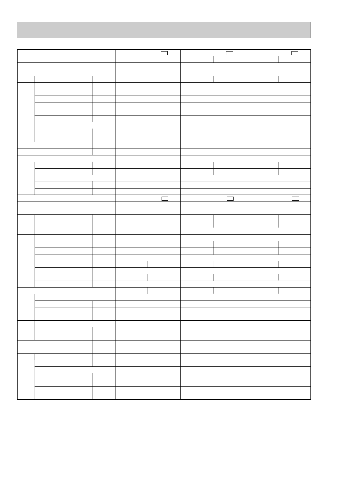
Indoor model
Function
Indoor unit power supply
Air flow(High/Med. /Low )
Power outlet
Running current
Power input
Power factor
Starting current
Fan motor current
Model
Winding
resistance(at20:)
Dimensions WOHOD
Weight
Air direction
Sound level(High/Med. /Low )
Fan speed(High/Med. /Low )
Fan speed regulator
Thermistor RT11(at25:)
Thermistor RT12(at25:)
Outdoor model
Capacity
Dehumidification
Outdoor air flow
Power outlet
Running current
Power input
Auxiliary heater
Power factor
Starting current
Compressor motor current
Fan motor current
Model
Output
Winding
resistance(at20:)
Model
Winding
resistance(at20:)
Dimensions WOHOD
Weight
Sound level
Fan speed
Fan speed regulator
Refrigerant filling
capacity(R22)
Refrigerating oil (Model)
Thermistor RT61(at0:)
K /h
A
A
W
%
A
A
"
mm
kg
dB
rpm
k"
k"
kW
R/h
K /h
A
A
W
A(kW)
%
A
A
A
W
"
"
mm
kg
dB
rpm
kg
cc
k"
MSC-07RV -
E4
Single phase
220-240V,50Hz
10
0.17
35
93.6-85.8
—
0.17
RC4V19-LA
WHT-BLK 413
BLK-RED 334
850O278O191
9
5
3
10
10
MUH-07RV -
E4
Single phase
220-240V,50Hz
1620-1752
10
—
25
0.21-0.22
RH-130VGCT
650
C-R 4.18
C-S 5.76
RA6V23-FB
WHT-BLK 353
BLK-RED 321
788o540o255
33
47
710-760
1
0.85
300 (MS56)
33.18
Cooling
474/384 /294
36/31 /26
950/790 /640
2.2
0.8
3.13-3.03
675-715
98.0-98.3
2.92-2.81
3.10-2.93
Heating
504/414 /336
35/30 /26
1000/850 /710
2.5
—
2.98-2.88
645-685
98.4-99.1
2.77-2.66
3.68-3.47
MSC-09RV -
E4
Single phase
220-240V,50Hz
10
0.17
35
93.6-85.8
—
0.17
RC4V19-LA
WHT-BLK 413
BLK-RED 334
850O278O191
9
5
3
10
10
MUH-09RV -
E4
Single phase
220-240V,50Hz
1620-1752
10
—
25
0.21-0.22
RH-165VGCT
800
C-R 3.30
C-S 5.80
RA6V23-FB
WHT-BLK 353
BLK-RED 321
780o540o255
33
47
710-760
1
0.85
300 (MS56)
33.18
Cooling
474/384 /294
36/31 /26
950/790 /640
2.5
1.1
3.93-3.83
845-885
97.7-96.3
3.72-3.61
2.84-2.72
Heating
504/414 /336
35/30 /26
1000/850 /710
3.1
—
4.13-3.93
885-905
97.4-95.9
3.92-3.71
3.37-3.30
MSC-12RV -
E4
Single phase
220-240V,50Hz
10
0.19
40
95.7-87.7
—
0.19
RC4V19-GA
WHT-BLK 375
BLK-RED 294
850O278O191
10
5
3
10
10
MUH-12RV -
E4
Single phase
220-240V,50Hz
1656-1758
10
—
35
0.29-0.32
RH-220VHAT
1050
C-R 2.13
C-S 3.91
RA6V33-DB
WHT-BLK 301
BLK-RED 332
780o540o255
38
49
810-840
1
1.19
520 (MS56)
33.18
Cooling
588/468 /360
39/34 /29
1020/850 /690
3.4
1.6
5.56-5.71
1180-1260
96.5-91.9
5.27-5.39
2.79-2.62
Heating
642/516 /402
39/34 /29
1100/920 /750
4.0
—
5.76-5.91
1220-1310
96.3-92.4
5.47-5.59
3.17-2.96
Electrical
data
Fan
motor
Special
remarks
Compressor
Electrical
data
Fan
motor
Special
remarks
Capacity
Coefficient of performance(C.O.P)
Outdoor unit power supply
Capacity
ww
ww
w
w
w
w
w
w
w
w
w
w
w
w
w
w
w
w
w
w
w
w
w
w
w
w
w
w
w
w
w
w
w
w
w
w
w
w
w
w
NOTE: Test conditions are based on ISO 5151.
Cooling : Indoor DB27°C WB19°C Heating : Indoor DB20°C
Indoor-Outdoor piping length 5m
Outdoor DB35°C WB24°C Outdoor DB 7°C / WB 6°C
w Reference value
12
 Loading...