


SPLIT-TYPE, AIR CONDITIONERS
No. OB396
SERVICE MANUAL
Wireless type
Models
MS-A08VD- P1
MS-A10VD- P1
MS-A13VD- P1
CONTENTS
Indication of model name MS-A08VD - P1 MS-A10VD - P1 MS-A13VD - P1
1.TECHNICAL CHANGES ················
2.PART NAMES AND FUNCTIONS············
3.SPECIFICATION····················
4.OUTLINES AND DIMENSIONS ·············
5.WIRING DIAGRAM ··················
6.REFRIGERANT SYSTEM DIAGRAM ···········
7.SERVICE FUNCTIONS ·················
8.TROUBLESHOOTING·················
9.DISASSEMBLY INSTRUCTIONS ············
10.PARTS LIST······················
TM |
NOTE:
•This service manual describes technical data of indoor units.
•As for outdoor units MU-A08VD - P1 ,MU-A10VD - P1 and MU-A13VD - P1 , refer to the service manual OB397.

1 TECHNICAL CHANGES
MS-07UV - P1 |
MS-A08VD - P1 |
MS-10UV - P1 |
MS-A10VD - P1 |
MS-13UV - P1 |
MS-A13VD - P1 |
1.Indoor unit has been changed.
•Front panel has been changed. (Grill Flat)
•Dimension has been changed. (850Wo278Ho191D 815Wo278Ho244D)
2.Easy clean function has been added.
3.Catechin air filter has been added.
4.Air cleaning filter has been added.
5.Fan motor has been changed.
6.Fan motor capacitor has been changed.
7.P.C. board has been changed.
8.Fin pattern of cooler has been changed.
9.Remote controller has been changed.
•OPERATE/STOP(ON/OFF) button and TEMPERATURE buttons have been remodeled to be luminous.
2

2 PART NAMES AND FUNCTIONS
INDOOR UNIT
MS-A08VD - P1
MS-A10VD - P1
MS-A13VD - P1
Air cleaning filter (white bellows type)
Panel
Catechin air filter (with deodorizing)
Air outlet
Vertical vanes
Fan
Horizontal vane
Operation section
(When the front panel is opened)
Emergency operation switch
Front panel
Air inlet

 to Breaker
Power supply cord
Remote control receiving section

 Remote controller
Display section
Operation indicator lamp
Remote control receiving section
ACCESSORIES
|
|
MS-A08VD - P1 |
|
|
MS-A10VD - P1 |
|
|
MS-A13VD - P1 |
1 |
Installation plate |
1 |
2 |
Installation plate fixing screw 4 x 25 mm |
5 |
3 |
Remote controller holder |
1 |
4 |
Fixing screw for 3 3.5 x 16 mm (Black) |
2 |
5 |
Battery (AAA) for remote controller |
2 |
6 |
Wireless remote controller |
1 |
7 |
Felt tape (Used for left or left-rear piping) |
1 |
8 |
Air cleaning filter |
2 |
3

REMOTE CONTROLLER
MS-A08VD - P1 MS-A10VD - P1 MS-A13VD - P1
Signal transmitting section
Operation display section 
 h
h
OPERATE/STOP (ON/OFF) button |
ON/OFF |
TOO |
TOO |
|
WARM |
COOL |
These buttons are able to store the light from nature, fluorescent lamp, etc and shine in the dark.
ECONO COOL button |
|
ECONO COOL |
FAN |
I FEEL COOL |
|
|
|
FAN |
DRY |
POWERFUL COOL |
VANE |
POWERFUL COOL button |
|
|
|
MODE |
SELECT |
TIME |
|
OPERATION SELECT button |
|
|
|
TIMER MODE SELECT button |
|
|
RESET |
|
|
|
|
TEMPERATURE buttons
FAN SPEED CONTROL button
VANE CONTROL button
TIME SET button
Indication of remote controller model is on back.
RESET button
3 SPECIFICATION
Indoor model
Function
Power supply
Capacity Air flow(High/Medw/Loww) |
|
K /h |
|
Electrical data |
Power outlet |
|
A |
Running current |
|
A |
|
|
|
||
|
Power input |
|
W |
|
Auxiliary heater |
|
A(kW) |
|
Fan motor current |
|
A |
Fan motor |
Model |
|
" |
Winding |
|
||
|
|
|
|
|
resistance(at 20:) |
|
|
|
Dimensions WOHOD |
|
mm |
|
Weight |
|
kg |
|
Air direction |
|
|
Special remarks |
Sound level (High/Medw/Loww) |
|
dB |
|
|||
Fan speed(High/Medw/Loww) |
|
rpm |
|
|
|
||
|
Fan speed regulator |
|
|
|
Thermistor RT11(at 25:) |
|
k" |
|
|
||
|
Thermistor RT12(at 25:) |
|
k" |
|
Remote controller model |
|
|
MS-A08VD - P1 |
|
MS-A10VD - P1 |
MS-A13VD - P1 |
||
|
|
Cooling |
|
||
|
|
|
|||
|
|
Single phase |
|
||
|
|
220-230-240V, 50Hz |
|
||
630/498w/360w |
630/558w/486w |
||||
|
10 |
|
|
||
|
0.17 |
|
|
0.19 |
|
|
35 |
|
|
40 |
|
|
0.17 |
|
|
|
|
|
|
|
|
||
|
|
|
0.19 |
||
|
RC4V19-JA |
RC4V19-HA |
|||
WHT-BLK 283 |
WHT-BLK 224 |
||||
BLK-RED 188 |
BLK-RED 318 |
||||
|
|
815O278O244 |
|
||
|
9 |
|
|
|
|
|
|
|
10 |
||
|
5 |
|
|
||
|
|
42/36w/29w |
|||
|
39/32w/26w |
||||
960/760w/550w |
960/850w/740w |
||||
|
3 |
|
|
||
|
10 |
|
|
||
|
10 |
|
|
||
|
|
MP04B |
|
||
NOTE: Test conditions are based on JIS C 9612.
Cooling : Indoor |
DB27°C / WB19°C |
Outdoor |
DB35°C / WB24°C |
Indoor-Outdoor piping length : 5 m
W Reference value
4
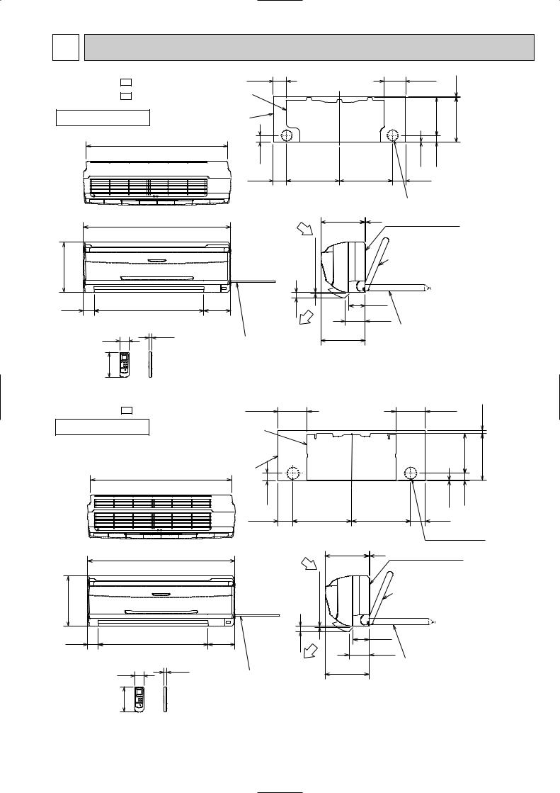
4 OUTLINES AND DIMENSIONS
MS-A08VD - P1 MS-A10VD - P1
INDOOR UNIT
81.5 |
|
|
133.5 |
4.5 |
Unit : mm |
|
Installation plate |
|
|
|
|
||
|
|
|
|
|
||
|
|
|
231.5 |
|
|
|
Indoor unit |
|
|
|
271 |
|
|
|
|
|
|
|
|
|
783 |
|
|
|
|
|
|
41 |
|
|
2.5 |
42 |
|
|
81.5 |
326 |
326 |
81.5 |
|
|
|
|
|
|
Wall hole [65 |
|
||
|
|
815 |
|
278 |
|
|
|
60 |
|
606 |
149 |
|
57 |
17.5 |
|
|
|
|
|
Power supply cord |
|
Lead to right 1.0m |
140 |
Lead to left 0.3m |
|
Air in |
242 |
5 |
Installation plate |
|
|
|
|
||
more |
|
|
{ |
Liquid line [6.35-0.5m |
|
|
Gas line [9.52-0.43m |
||
7 or |
|
|
Insulation [37 O.D |
|
|
|
|
[21 I.D |
|
30 |
|
90 |
|
Drain hose [16 |
|
110 |
|||
|
|
(Connected part O,D) |
||
|
|
|
|
|
Air out |
244 |
|
|
Insulation [28 |
|
|
|
|
|
Wireless remote controller |
|
|
|
|
|
|
|
||
MS-A13VD - P1 |
|
161.5 |
|
|
|
|
161.5 |
|
17.5 |
|
|
|
|
|
|
|
|
||
INDOOR UNIT |
|
Installation plate |
|
|
|
|
|
|
|
|
|
|
|
|
|
|
|
||
|
|
Indoor unit |
|
|
|
|
|
218.5 |
258 |
|
783 |
|
|
|
|
|
|
|
|
|
|
|
|
|
|
|
|
|
|
|
|
41 |
|
|
|
|
2.5 |
42 |
|
|
|
81.5 |
326 |
|
326 |
|
81.5 |
|
|
|
|
|
|
|
|
|
Wall hole [65 |
||
|
815 |
|
Air in |
242 |
5 |
Installation plate |
|
||
|
|
|
|
|
|
||||
278 |
|
|
moreor |
|
|
|
Liquid line [6.35-0.5m |
||
|
|
|
|
|
Gas line [9.52-0.43m |
||||
|
|
|
|
|
|
{ Insulation [37 O.D |
|||
|
|
|
7 |
|
|
|
[21 I.D |
||
60 |
606 |
149 |
30 |
|
90 |
|
Drain hose [16 |
|
|
|
110 |
|
|||||||
|
|
|
|
|
|||||
|
|
|
|
|
(Connected part O,D) |
||||
|
|
|
|
|
|
|
|||
57 |
|
17.5 |
Air out |
244 |
|
|
Insulation [28 |
|
|
|
|
|
|
|
|
|
|||
|
|
Power supply cord |
|
|
|
|
|
|
|
|
|
Lead to right 1.0m |
|
|
|
|
|
|
|
140 |
|
Lead to left 0.3m |
|
|
|
|
|
|
|
|
|
|
|
|
|
|
|
|
|
Wireless remote controller
5

5 |
WIRING DIAGRAM |
|
|
|
|
|
|
|
|
|
|||||
MS-A08VD - P1 |
MS-A10VD - P1 |
MS-A13VD - P1 |
|
|
|
|
|
|
|
|
|||||
INDOOR UNIT |
|
|
|
MODELS WIRING DIAGRAM |
|
|
|
|
|||||||
|
|
LTB |
BRN |
|
|
|
|
|
|
|
|
CN |
|
RT12 |
|
|
|
|
BRN |
|
|
|
|
|
|
|
|
112 |
|
|
|
TO OUTDOOR |
|
|
|
|
|
|
|
|
|
CN |
|
RT11 |
|||
UNIT |
|
|
|
|
|
|
CN201 |
|
|
T11 |
|
111 |
|
||
CONNECTING |
|
|
|
|
|
|
|
|
|
|
BLK |
|
|||
220-230-240V~ |
2 |
WHT |
F12 BLU |
|
|
3 |
|
|
3 |
|
|
3 |
1 |
||
|
|
|
|
52C |
NR11 |
CN |
GRY |
||||||||
1 |
|
2 |
|
|
|||||||||||
|
|
|
|
BLU |
BLU |
|
|
4 |
|
121 |
|
YLW |
2 |
||
|
|
N |
|
2 |
1 |
|
|
|
|
|
|
3 |
|||
|
|
BLU |
|
|
|
|
|
|
|
C11 |
1 |
|
BRN |
4 MF |
|
|
|
|
|
|
|
|
|
|
|
|
|||||
|
|
BLU |
|
|
LD103 |
|
|
|
F11 |
SR141 |
3 |
|
WHT |
5 |
|
|
|
|
|
|
|
|
|
|
|
RED |
|||||
|
|
|
|
|
|
|
|
|
|
|
5 |
|
6 |
||
|
|
|
|
|
|
CN |
CN |
CN |
|
CN |
CN211 |
|
|
|
|
|
|
|
|
|
|
151 |
1R1 |
109 |
125 |
|
|
|
|
|
|
|
|
|
GRN/YLW |
|
|
|
|
|
|
ELECTRONIC CONTROL P.C. BOARD |
|
|
|
||
|
|
GRN/YLW |
GRN |
|
5 |
2 |
|
3 |
2 |
|
|
|
|
|
|
|
|
|
|
SAFETY |
|
|
POWER MONITOR, |
|
|
|
|
|
|||
|
POWER |
|
MV |
|
|
RECEIVER |
|
|
|
|
|
||||
|
|
|
|
|
DEVICE(FAN) |
|
|
|
|
|
|
|
|||
|
|
|
|
|
|
|
P.C.BOARD |
|
|
|
|
|
|||
|
SUPPLY |
|
|
|
|
|
|
|
|
|
|
|
|
||
|
CORD |
|
|
|
|
|
|
|
|
|
REMOTE |
|
|
|
|
|
220-230-240V |
|
|
|
|
|
|
|
|
CONTROLLER |
|
|
|
||
|
~/N 50Hz |
|
|
|
|
|
|
|
|
|
|
|
|
||
|
|
|
|
|
|
|
|
|
|
|
|
|
|
|
|
SYMBOL |
NAME |
SYMBOL |
NAME |
SYMBOL |
NAME |
|
|
|
|
|
|
C11 |
INDOOR FAN CAPACITOR |
MV |
VANE MOTOR |
SR141 |
SOLID STATE RELAY |
|
|
|
|
|
|
F11 |
FUSE(3.15A) |
NR11 |
VARISTOR |
TB |
TERMINAL BLOCK |
|
|
|
|
|
|
F12 |
THERMAL FUSE(93:) |
RT11 |
ROOM TEMPERATURE THERMISTOR |
T11 |
TRANSFORMER |
MF |
INDOOR FAN MOTOR(INNER FUSE) |
RT12 |
INDOOR COIL THERMISTOR |
52C |
CONTACTOR |
NOTE:1. About the outdoor side electric wiring refer to the outdoor unit electric wiring diagram for servicing.
2.Use copper conductors only. (For field wiring)
3.Symbols below indicate.
/: Terminal block,  : Connector
6 REFRIGERANT SYSTEM DIAGRAM
MS-A08VD - P1 |
|
|
|
|
|
|
|
|
|
|
MS-A13VD - P1 |
|
|
|
|
|
|
|
|
Unit : mm |
|||||||||||||||||||||||||||||||||||||
MS-A10VD - P1 |
|
|
|
|
|
Refrigerant pipe |
|
|
|
|
|
|
|
|
|
|
|
|
|
|
|
|
|
|
|
|
|
|
|
|
Refrigerant pipe |
||||||||||||||||||||||||||
|
|
|
INDOOR UNIT |
|
|
(Option){9.52 |
|
INDOOR UNIT |
|
|
(Option){12.7 |
||||||||||||||||||||||||||||||||||||||||||||||
|
|
|
|
|
|
|
|
|
|
|
|
|
|
|
|
|
|
|
|
|
|
|
|
|
(with heat insulator) |
|
|
|
|
|
|
|
|
|
|
|
|
|
|
|
|
|
|
|
|
|
|
|
|
(with heat insulator) |
|||||||
|
|
|
|
|
|
|
|
|
|
|
|
|
|
|
|
|
|
|
|
|
|
|
|
|
|
|
|
|
|
|
|
|
|
|
|
|
|
|
|
|
|
|
|
|
|
|
|
|
|||||||||
|
|
|
|
|
|
|
|
|
|
|
|
|
|
|
|
|
|
|
|
|
|
|
|
|
|
|
|
|
|
|
|
|
|
|
|
|
|
|
|
|
|
|
|
|
|
|
|
|
|
|
|
|
|
|
|
|
|
|
|
|
|
|
|
|
|
|
|
|
|
|
|
|
|
|
|
|
|
|
|
|
|
|
|
|
|
|
|
|
|
|
|
|
|
|
|
|
|
|
|
|
|
|
|
|
|
|
|
|
|
|
|
|
|
|
|
|
|
|
|
|
|
|
|
|
|
|
|
|
|
|
|
|
|
|
|
|
|
|
|
|
|
|
|
|
|
|
|
|
|
|
|
|
|
|
|
|
|
|
|
|
|
|
|
|
|
||||||||
|
|
|
|
|
|
Indoor |
|
|
|
|
|
Indoor coil |
|
|
|
|
|
|
|
|
|
|
Indoor |
|
|
|
|
|
|
|
|
|
|
|
|
|
|||||||||||||||||||||
|
|
|
|
|
|
heat |
|
|
|
|
|
|
|
|
|
|
|
|
|
|
|
heat |
|
|
|
|
|
|
|
|
|
|
|
|
|
||||||||||||||||||||||
|
|
|
|
|
|
exchanger |
|
|
|
|
|
thermistor |
|
Flared |
|
|
|
|
|
|
exchanger |
|
|
|
|
Indoor coil Flared |
|||||||||||||||||||||||||||||||
|
|
|
|
|
|
|
|
|
|
|
|
|
|
|
|
|
|
|
|
RT12 |
|
|
|
|
|
|
|
|
|
|
|
|
|
|
|
|
|
|
|
|
|||||||||||||||||
|
|
|
|
|
|
|
|
|
|
|
|
|
|
|
|
|
|
|
|
|
connection |
|
|
|
|
|
|
|
|
|
|
|
|
|
|
|
|
|
|
|
thermistor |
connection |
|||||||||||||||
|
|
|
|
|
|
|
|
|
|
|
|
|
|
|
|
|
|
|
|
|
|
|
|
|
|
|
|
|
|
|
|
|
|
|
|
|
|
|
|
|
|
|
|
|
|||||||||||||
|
|
|
|
|
|
|
|
|
|
|
|
|
|
|
|
|
|
|
|
|
|
|
|
|
|
|
|
|
|
|
|
|
|
|
|
|
|
|
|
|
|
|
|
|
|
|
|
|
RT12 |
|
|
|
|
||||
|
|
|
|
|
|
|
|
|
|
|
|
|
|
|
|
|
|
|
|
|
|
|
|
|
|
|
|
|
|
|
|
|
|
|
|
|
|
|
|
|
|
|
|
|
|
|
|
|
|
|
|
|
|
|
|
|
|
|
|
|
|
|
|
|
|
|
|
|
|
|
|
|
|
|
|
|
|
|
|
|
|
|
|
|
|
|
|
|
|
|
|
|
|
|
|
|
|
|
|
|
|
|
|
|
|
|
|
|
|
|
|
|
|
|
|
|
|
|
|
|
|
|
|
|
|
|
|
|
|
|
|
|
|
|
|
|
|
|
|
|
|
|
|
|
|
|
|
|
|
|
|
|
|
|
|
|
|
|
|
|
|
|
|
|
|
|
|
|
|
|
|
|
|
|
|
|
|
RT11 |
|
|
|
|
|
|
|
|
|
|
|
|
|
|
RT11 |
|
|
|
|
|
|
|
|
|
|||||||||||||||||||||||||||||
|
|
|
|
Room |
|
|
|
|
|
|
|
|
|
|
|
|
|
|
Room |
|
|
|
|
|
|
|
|
|
|||||||||||||||||||||||||||||
|
|
|
|
temperature |
|
|
|
|
|
|
Flared |
|
|
|
|
temperature |
|
|
|
|
|
Flared |
|||||||||||||||||||||||||||||||||||
|
|
|
|
thermistor |
|
|
|
|
|
|
|
|
|
|
thermistor |
|
|
|
|
|
|||||||||||||||||||||||||||||||||||||
|
|
|
|
|
|
|
|
|
|
|
|
|
|
|
|
|
|
||||||||||||||||||||||||||||||||||||||||
|
|
|
|
|
|
|
|
|
|
|
|
|
|
|
|
|
|
|
|
|
|
|
|
|
|
connection |
|
|
|
|
|
|
|
|
|
|
|
|
|
|
|
|
|
|
|
|
|
|
|
|
connection |
||||||
|
|
|
|
|
|
|
|
|
|
|
|
|
|
|
|
|
|
|
|
|
|
|
|
|
|
|
|
|
|
|
|
|
|
|
|
|
|
|
|
|
|
|
|
|
|
|
|
|
|
|
|
|
|
|
|
|
|
|
|
|
|
|
|
|
|
|
|
|
|
|
|
|
|
|
|
|
|
|
|
|
|
|
|
|
|
|
|
|
|
|
|
|
|
|
|
|
|
|
|
|
|
|
|
|
|
|
|
|
|
|
|
|
|
|
|
|
|
|
|
|
|
|
|
|
|
|
|
|
|
|
|
|
|
|
|
|
|
|
|
|
|
|
|
|
|
|
|
|
|
|
|
|
|
|
|
|
|
|
|
|
|
|
|
|
|
|
|
|
|
|
|
|
|
Refrigerant pipe |
Refrigerant pipe |
(Option){6.35 |
(Option){6.35 |
(with heat insulator) |
(with heat insulator) |
Refrigerant flow in cooling
6
7 SERVICE FUNCTIONS
MS-A08VD - P1
MS-A10VD - P1
MS-A13VD - P1
7-1. TIMER SHORT MODE
For service, set time can be shortened by short circuit of JPG and JPS the electronic control P.C. board. The time will be shortened as follows. (Refer to 8-6.)
Set time : 1-minute 1-second Set time : 3-minute 3-second
It takes 3 minutes for the compressor to start operation. However, the starting time is shortened by short circuit of JPG and JPS.
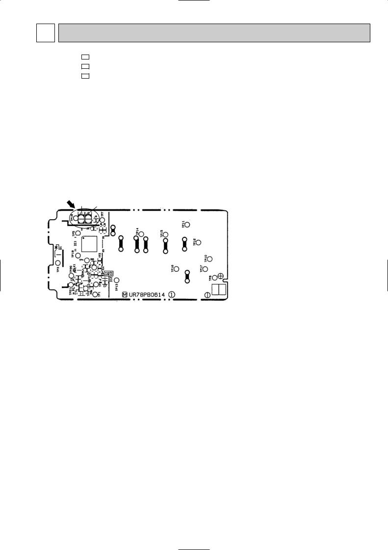
7-2. P.C. BOARD MODIFICATION FOR INDIVIDUAL OPERATION
A maximum of 4 indoor units with wireless remote controllers can be used in a room.
In this case, to operate each indoor unit individually by each remote controller, P.C. boards of remote controller must be modified according to the number of the indoor unit.
How to modify the remote controller P.C. board
Remove batteries before modification.
The board has a print as shown below :
Remote controller model : MP04B
J2
NOTE : For remodelling, take out the batteries and push the OPERATE/STOP(ON/OFF)button twice or 3 times at first.
After finish remodelling, put back the batteries then press the RESET button.
The P.C. board has the print “J1” and “J2”. Solder “J1” and “J2” according to the number of indoor unit as shown in Table 1. After modification, press the RESET button.
7
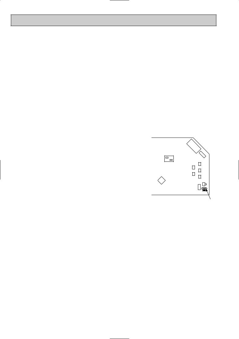
Table 1
|
1 unit operation |
2 units operation |
3 units operation |
4 units operation |
|
|
|
|
|
No. 1 unit |
No modification |
Same as at left |
Same as at left |
Same as at left |
|
|
|
|
|
No. 2 unit |
– |
Solder J1 |
Same as at left |
Same as at left |
|
|
|
|
|
No. 3 unit |
– |
– |
Solder J2 |
Same as at left |
|
|
|
|
|
No. 4 unit |
– |
– |
– |
Solder both J1 and J2 |
|
|
|
|
|
How to set the remote controller exclusively for particular indoor unit
After you turn the breaker ON, the first remote controller that sends the signal to the indoor unit will be regarded as the remote controller for the indoor unit.
The indoor unit only accepts the signal from the remote controller that has been assigned to the indoor unit once they are set.
The setting will be cancelled if the breaker has turned off, or the power supply has shut down. Please conduct the above setting once again after the power has restored.
7-3. AUTO RESTART FUNCTION
When the indoor unit is controlled with the remote controller, the operation mode, set temperature, and the fan speed are memorized by the indoor electronic control P.C.board. The “AUTO RESTART FUNCTION” sets to work the moment power has restored after power failure. Then, the unit will restart automatically. However if the unit is operated in “I FEEL CONTROL” mode before power failure, the operation is not memorized. In “I FEEL CONTROL” mode, the operation is decided by the initial room temperature.
Operation
1If the main power has been cut, the operation settings remain.
2After the power is restored, the unit automatically resumes the same operation as the memory has recorded.
However, it takes the compressor at least 3 minutes to get started.
How to release “AUT O RESTART FUNCTION”
1Turn off the main power for the unit.
2Pull out the indoor electronic control P.C. board and the power monitor, receiver P.C. board. (Refer to 9-1.)
3Solder the Jumper wire to the JR07 on the indoor electronic control P.C.board. (Refer to 8-6.)
52C
IC101
CN201

C1 1
CN21 |
|
|
1 |
CN111 CN1V1 |
CN112CN121 CN1R1 |
CN151 |
SW1 |
|
|
JR07
NOTE:
•The operation settings are memorized when 10 seconds have passed after the indoor unit was operated with the remote controller.
•If the main power is turned off or a power failure occurs while AUTO START/STOP timer is active, the timer setting is cancelled.
•If the unit has been off with the remote controller before power failure, the auto restart function does not work as the power button of the remote controller is off.
•To prevent breaker off due to the rush of starting current, systematize other home appliances not to turn on at the same time.
•When some air conditioners are connected to the same supply system, if they are operated before power failure, the starting current of all the compressors may flow simultaneously at restart.
Therefore, the special counter-measures are required to prevent the main voltage-drop or the rush of the starting current by adding to the system that allows the units to start one by one.
8
 Loading...