


 Loading...
SERVICE MANUAL
Model
DF-314
SECOND EDITION
NOVEMBER 2000
CSM-DF314
KONICA BUSINESS TECHNOLOGIES, INC.

DF-314
SERVICE MANUAL
NOVEMBER 2000
SECOND EDITION

IMPORTANT NOTICE
Because of the possible hazards to an inexperienced person servicing this equipment, as well as the risk of damage to the equipment, Konica Business Technologies strongly recommends that all servicing be performed by Konica-trained service technicians only.
Changes may have been made to this equipment to improve its performance after this service manual was printed. Accordingly, Konica Business Technologies, Inc., makes no representations or warranties, either expressed or implied, that the information contained in this service manual is complete or accurate. It is understood that the user of this manual must assume all risks or personal injury and/or damage to the equipment while servicing the equipment for which this service manual is intended.
Corporate Publications Department
© 2000, KONICA BUSINESS TECHNOLOGIES, INC. All rights reserved.
Printed in U.S.A.

DF-314
CONTENTS |
|
OUTLINE |
|
DF-314 PRODUCT SPECIFICATIONS ........................... |
1 |
Type ......................................................................... |
1 |
Functions ................................................................. |
1 |
Machine data ........................................................... |
1 |
Maintenance ............................................................ |
1 |
Machine environment .............................................. |
1 |
CENTER CROSS-SECTIONAL DIAGRAM ...................... |
2 |
DRIVE SYSTEM DIAGRAM .............................................. |
3 |
ORIGINAL CONVEYANCE PROCESS ............................ |
4 |
Single-side original copy mode .............................. |
4 |
Double-side original copy mode ............................. |
5 |
Mixed original copy mode ........................................ |
5 |
UNIT EXPLANATION |
|
EXTERNAL SECTION .................................................... |
7 |
Composition ............................................................. |
7 |
Mechanisms ............................................................. |
7 |
ORIGINAL FEED/REVERSAL/ORIGINAL EXIT |
|
SECTION ........................................................................ |
8 |
Composition ............................................................. |
8 |
Mechanisms ............................................................. |
8 |
Original feed/conveyance/scan control ................... |
9 |
Original exit/reversal and conveyance |
|
control .................................................................. |
11 |
Original size detection control ............................... |
13 |
DISASSEMBLY/ASSEMBLY |
|
DISASSEMBLY/ASSEMBLY ......................................... |
15 |
Replacing feed roller/A .......................................... |
15 |
Replacing the double-feed prevention |
|
roller/A assy ......................................................... |
15 |
Replacing read roller ............................................... |
1 |
DIAGRAMS |
|
ELECTRICAL PARTS LAYOUT ..................................... |
17 |
CONNECTOR LAYOUT ................................................ |
18 |
TIME CHART (8.5 X 11, 1-SIDED ORIGINAL, 3 |
|
SHEETS) ..................................................................... |
19 |
TIME CHART (8.5 X 11, 2-SIDED ORIGINAL, 2 |
|
SHEETS) ..................................................................... |
20 |
OVERALL WIRING DIAGRAM ...................................... |
21 |
iii

DF-314
This page left blank intentionally.
iv

SAFETY PRECAUTIONS
SAFETY PRECAUTIONS
Installation Environment
Safety considerations usually are directed toward machine design and the possibility of human error. In addition, the environment in which a machine is operated must not be overlooked as a potential safety hazard.
Most electrical equipment is safe when installed in a normal environment. However, if the environment is different from what most people consider to be normal, it is conceivable that the combination of the machine and the room air could present a hazardous combination. This is because heat (such as from fusing units) and electrical arcs (which can occur inside switches) have the ability to ignite flammable substances, including air.
When installing a machine, check to see if there is anything nearby which suggests that a potential hazard might exist. For example, a laboratory might use organic compounds which, when they evaporate, make the room air volatile. Potentially dangerous conditions might be seen or smelled. The presence of substances such as cleaners, paint thinners, gasoline, alcohol, solvents, explosives, or similar items should be cause for concern.
If conditions such as these exist, take appropriate action, such as one of the following suggestions.
∙Determine that the environment is controlled (such as through the use of an exhaust hood) so that an offending substance or its fumes cannot reach the machine.
∙Remove the offending substance.
∙Install the machine in a different location.
The specific remedy will vary from site to site, but the principles remain the same. To avoid the risk of injury or damage, be alert for changes in the environment when performing subsequent service on any machine, and take appropriate action.
Unauthorized Modifications
Konica copiers have gained a reputation for being reliable products. This has been attained by a combination of outstanding design and a knowledgeable service force.
The design of the copier is extremely important. It is the design process that determines tolerances and safety margins for mechanical, electrical, and electronic aspects. It is not reasonable to expect individuals not involved in product engineering to know what
effect may be caused by altering any aspect of the machine’s design. Such changes have the potential of degrading product performance and reducing safety margins.
For these reasons, installation of any modification not specifically authorized by Konica Business Machines U.S.A., Inc., is strictly prohibited.
The following list of prohibited actions is not all-inclu- sive, but demonstrates the intent of this policy.
∙Using an extension cord or any unauthorized power cord adapter.
∙Installing any fuse whose rating and physical size differs from that originally installed.
∙Using wire, paper clips, solder, etc., to replace or eliminate any fuse (including temperature fuses).
∙Removing (except for replacement) any air filter.
∙Defeating the operation of relays by any means (such as wedging paper between contacts).
∙Causing the machine to operate in a fashion other than as it was designed.
∙Making any change which might have a chance of defeating built-in safety features.
∙Using any unspecified replacement parts.
General Safety Guidelines
This copier has been examined in accordance with the laws pertaining to various product safety regulations prior to leaving the manufacturing facility to protect the operators and service personnel from injury. However, as with any operating device, components will break down through the wear-and-tear of everyday use, as will additional safety discrepancies be discovered. For this reason, it is important that the technician periodically performs safety checks on the copier to maintain optimum reliability and safety.
The following checks, not all-inclusive, should be made during each service call:
CAUTION: Avoid injury. Ensure that the copier is disconnected from its power source before continuing.
∙Look for sharp edges, burrs, and damage on all external covers and copier frame.
∙Inspect all cover hinges for wear (loose or broken).
∙Inspect cables for wear, frays, or pinched areas.
v

SAFETY PRECAUTIONS
∙Ensure that the power cord insulation is not damaged (no exposed electrical conductors).
∙Ensure that the power cord is properly mounted to the frame by cord clamps.
∙Check the continuity from the round lug (GND) of the power cord to the frame of the copier -- ensure continuity. An improperly grounded machine can cause an electrically-charged machine frame.
Safeguards During Service Calls
Confirm that all screws, parts, and wiring which are removed during maintenance are installed in their original positions.
∙When disconnecting connectors, do not pull the wiring, particularly on AC line wiring and high voltage parts.
∙Do not route the power cord where it is likely to be stepped on or crushed.
∙Carefully remove all toner and dirt adhering to any electrical units or electrodes.
∙After part replacement or repair work, route the wiring in such a way that it does not contact any burrs or sharp edges.
∙Do not make any adjustments outside of the specified range.
Applying Isopropyl Alcohol
Care should be exercised when using isopropyl alcohol, due to its flammability. When using alcohol to clean parts, observe the following precautions:
∙Remove power from the equipment.
∙Use alcohol in small quantities to avoid spillage or puddling. Any spillage should be cleaned up with rags and disposed of properly.
∙Be sure that there is adequate ventilation.
∙Allow a surface which has been in contact with alcohol to dry for a few minutes to ensure that the alcohol has evaporated completely before applying power or installing covers.
Summary
It is the responsibility of every technician to use professional skills when servicing Konica products. There are no short cuts to high-quality service. Each copier must be thoroughly inspected with respect to safety considerations as part of every routine service call. The operability of the copier, and more importantly, the safety of those who operate or service the copier, are directly dependent upon the conscientious effort of each and every technician.
Remember...when performing service calls, use good judgement (have a watchful eye) to identify safety hazards or potential safety hazards that may be present, and correct these problem areas as they are identified -- the safety of those who operate the copier as well as those who service the copier depend on it!
vi
DF-314
DF-314 PRODUCT SPECIFICATIONS
Type
Type: Sheet-through type reversible DF
Functions
Originals Size: 11x17, 8.5x14, 8x13, 8.5x11,
8.5x11R, 5.5x8.5, 5.5x8.5R
•All sizes are detected automatically.
•Mixing of original size possible.
Original Type
Plain Original: 10 lb. - 35 lb. fine quality original
Special Original: Original feed and conveyance ability may be inferior those of 10 lb. to 35 lb. fine quality original.
The following types of original cannot be used:
•OHP film
•Blueprint masters
•Offset masters
•Bonded original
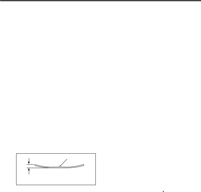
Original Curling: 10mm maximum (10 lb. to 35 lb. high-quality paper)
Original
Curling
Maximum Number of Stacked Originals:
50 sheets maximum (22 lb.)
Original Scan Speed (Copies Per Minute)
Mode |
|
Original |
Feed |
||
|
|
size |
speed |
||
|
|
|
|
|
|
Single sided Original → |
|
|
|
|
30 |
|
8.A45x11 |
||||
Single sided Copy |
|
|
|
|
|
|
|
|
|
|
|
Double sided Original → |
|
|
|
|
|
|
8.A45x11 |
18 |
|||
Double sided Copy |
|
|
|
|
|
|
|
|
|
|
|
Original Feed Layout:
Face-up placement, center standard
Original image read Position:
At the slit glass section
Machine data
Power Source: DC24V/5V (supplied from the main body)
Maximum Power Consumption:
|
Maximum 100VA |
Weight: |
Approximately 24 lb. |
|
(including about 2.5 lb. for |
|
platen) |
Machine Dimensions: Length 22.7 in
Depth 19.6 in.
Height 3.9 in.
Maintenance
Maintenance: |
Same as the main unit |
Machine environment
Temperature: |
50 to 86 F |
Humidity: |
10 to 80%RH |
|
(below condensation-forming |
|
conditions) |
Caution: The contents of this service manual are subject to change without notice.
1
DF-314 |
|
|
CENTER CROSS-SECTIONAL DIAGRAM |
||
|
Separation roller |
|
Registration roller |
||
Reversal guide |
Original feed roller |
|
Paper lift-up plate |
||
|
||
Read out |
|
|
roller |
|
|
|
Double feed prevention roller |
|
|
Reversal roller |
|
Original conveyance rollers |
Original exit roller |
|
|
Exit guide |
|
2

DF-314
DRIVE SYSTEM DIAGRAM
Original feed motor (M301) |
Separation roller |
||
|
Original feed roller |
||
|
|
||
Original reversal motor (M303) |
|
Paper lift-up plate |
|
|
|
||
|
Registration |
|
|
|
roller |
|
|
Original conveyance motor (M302) |
Double feed |
Feed drive |
|
prevention roller |
|||
|
|||
Original exit roller |
|
Reversal roller |
|
|
|
||
|
|
Reversal drive |
|
|
|
Roller pressure SD (SD302) |
|
|
Reversal guide |
|
|
Exit guide |
|
|
|
|
Conveyance/exit drive |
||
Exit SD (SD303) |
|
||
*Reversal and Exit Rollers
A reversal roller pulley is attached to the original exit roller shaft. The reversal roller conveys the original through pressure being applied on the pulley by the roller pressure SD.
Original exit roller |
Reversal roller |
Pulley |
Roller pressure SD (SD302) |
3
DF-314
ORIGINAL CONVEYANCE PROCESS
As illustrated below, the DF-314 is made up of a original feed section, conveyance section, original exit section and reversal section.
Conveyance |
Original feed section |
section |
|
|
Reversal section |
Slit glass |
Original exit section |
|
|
(Read section) |
|
With the originals set face-up on the original feed tray, they are fed from the topmost original. Rather than being conveyed to an original glass surface, the originals that are fed in and read when they pass a slit glass placed in the conveyance path.
There are 3 modes in the DF-314 operation mode, singleside original copy mode, double-side original copy mode, and mixed original copy mode, and the conveyance path differs according to each mode.
Single-Side Original Copy Mode
(Single-side to single-side copy, single-side to double-side copy)
The original that has been set in the paper feed tray is lifted by the paper lift-up plate so it comes into contact with the original feed roller. The original feed roller and the separation roller pre-feed to the position where P311 (original registration PS) turns on.
|
Separation roller |
Registration roller |
Original feed roller |
|
Paper lift-up plate |
Original registration PS (PS311) |
|
When PS311 turns ON, the original is re-fed by the registration roller and conveyed to the original conveyance roller. The original conveyance roller conveys the original to the position where PS312 (original feed PS) turns ON.
Conveyance rollers |
Registration roller |
|
|
||
Original feed PS |
Original registration |
|
PS (PS311) |
||
(PS312) |
||
|
The conveyance roller turns, and scanning starts. If there is another original waiting, it is pre-fed at this point.
The scanning of the original is conveyed out when the original passes over the slit glass. The original which has been read is exited to the original exit tray by the original exit roller with the exit SD OFF (i.e. with the exit guide raised).
|
Next original |
|
Original exit roller |
Slit glass |
Exit guide |
|
4
DF-314
Double-side Original Copy Mode
(Double-side to single-side copy, double-side to double-side copy)
The original set in the original feed tray is pre-fed to the position where PS311 (original registration PS) turns ON by the original feed roller and the separation roller. When PS311 turns ON, the reversal guide opens, the registration roller conveys the original to the reversal section, and the reversal roller conveys the original into the interior of the reversal section.
Reversal guide |
Registration roller |
|
Reversal roller |
Original registration PS (PS311) |
|
After the specified period from when PS311 detects the training edge of the original and goes OFF, the original is conveyed to the stop position at the front edge of the reversal guide. As the original has been reversed at this point, the reversal roller is made to rotate in reverse and it conveys the original to the original conveyance roller. If there is another original waiting, it is pre-fed at this timing.
The original conveyance roller conveys the original to the position where PS312 turns ON and the reading of the original back side starts.
Reversal guide |
Next original |
Flapper |
|
Conveyance roller |
Reversal roller |
|
The exit SD comes ON (the exit guide is lowered) when scanning of the rear side of the original begins, and the original is again conveyed to the reversal roller. When PS312 detects the rear edge of the original and turns OFF, the original is conveyed as far as the stop position in front of the reversal gate by the timer. The original has been reversed once again by this point so is conveyed to the original conveyance roller. The original conveyance roller conveys the original and reading of the original face side starts.
Flapper |
Next original |
|
Reversal roller |
|
Exit guide |
Original conveyance |
Slit glass |
PS (PS312) |
|
The original which has been read is exited to the original exit tray by the original exit roller with the exit SD OFF (i.e. with the paper exit guide raised). If there is another original, it is conveyed to the reversal section at this point.
|
Next original |
Reversal roller |
|
|
Exit roller |
Slit glass |
Exit guide |
|
Mixed Original Copy Mode
The mixed original copy mode supports both same-series originals and different series originals, but as size detection is performed in PS311 ON time, size detection is performed before reading.
After the size of the original is detected, the original stops at the reversal position. Subsequently, operation is the same as that of the two-sided copy mode.
Refer to "ORIGINAL FEED/REVERSAL/ORIGINAL EXIT SECTION/Original size detection control" for size detection operation.
5

DF-314
This page left blank intentionally.
6
DF-314
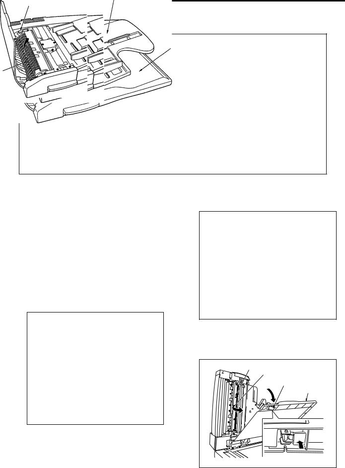
EXTERNAL SECTION
Composition
Original feed tray
Original exit tray
Jam access cover
Mechanisms
Mechanism |
System |
|
|
Jam release* |
Jam access cover |
|
Reversal guide open/close lever |
|
RADF Main body open/close |
|
Knob |
|
Exit-guide open/close lever |
|
Platen separation lever |
|
|
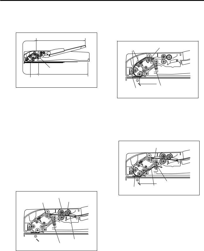
* Jam removal
If a jam occurs at the original feed, open the Jam access cover and turning the knob closer to you withdraw the sheet.
Jam
access
cover
If a jam occurs in the reversal section, open the reversal guide with the reversal guide open/close lever and withdraw the sheet.
Reversal
guide
If a jam occurs in the conveyance section, open the exit tray (using the platen separation lever) and the exit guide (using the exit-guide open/ close lever) and withdraw the sheet.
Exit guide |
Exit guide open/close lever |
Platen separation lever |
Original exit tray |
7
DF-314
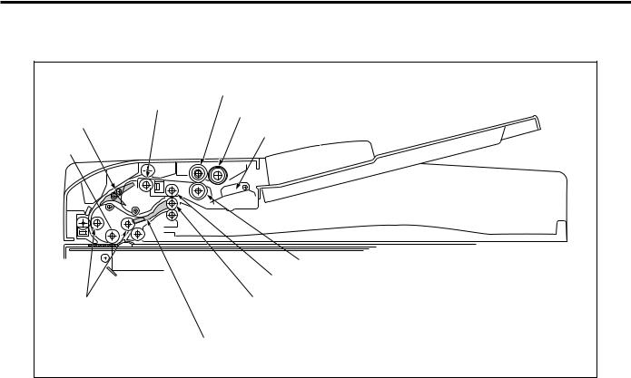
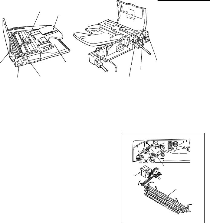
ORIGINAL FEED/REVERSAL/ORIGINAL EXIT SECTION
Composition
Jam |
|
conveyance |
|
|
|
|
|
motor (M303) |
Exit SD (SD303) |
Roller pressure SD (SD302) |
Original feed motor (M301) |
|
|
|
Mechanisms
Mechanism |
System |
|
|
Original feed |
Feed roller |
|
|
Double feed prevention |
Separation roller |
|
Double feed prevention |
|
Roller |
|
|
Original conveyance |
Original conveyance rollers |
|
|
Original reverse and |
Reversal guide |
feed *1 |
|
|
|
Original exit path |
Original exit guide |
section *2 |
|
|
|
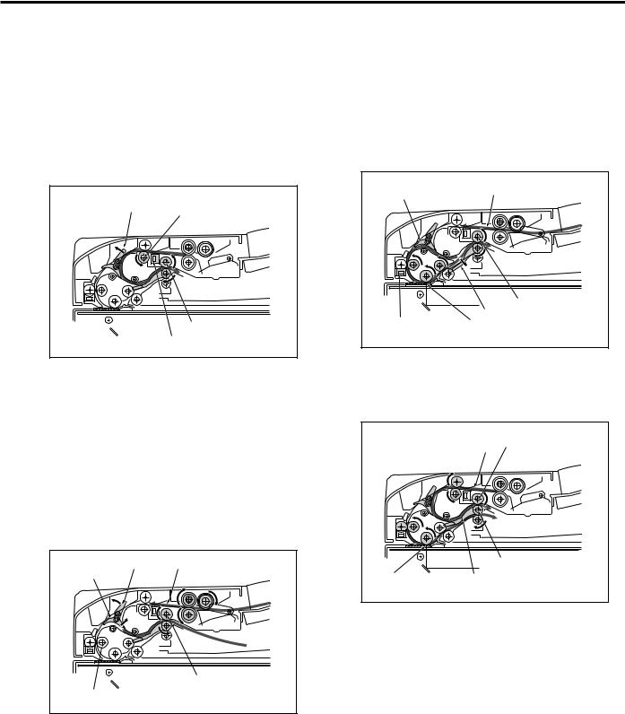
*1: Reversed original feed
During double-side copying, in order to reverse the original the paper feed path is switched by the reversal guide, the paper is conveyed to the reverse mechanism and is reversed.
Reversal guide
Original
reversal
Reversal guide
motor
(M303)
8
DF-314
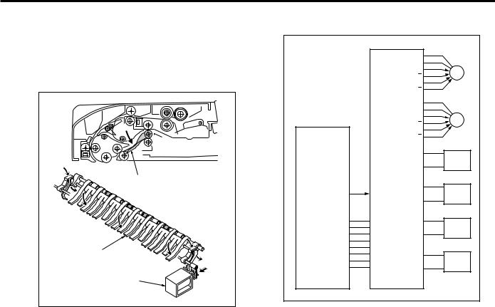
*2: Original exit path switching
In the case of a two-sided copy, the paper exit guide changes over the paper feed path so as to either exit the original directly, or feed the original to the reversal section in order to read it once again.
Exit guide |
Exit guide |
Exit SD (SD303) |
Original Feed/Conveyance/Scan Control
M TXD  M REQ
M REQ  S ACK
S ACK  M ACK
M ACK  S TXD
S TXD  S REQ
S REQ 
VV
24VDC
24VDC PGND PGND 5VDC SGND SGND 5VDC
24VDC
24VDC M301 OUT A
M301 OUT A
M301
M301 OUT B
M301 OUT B
24VDC
24VDC M302 OUT A
M302 OUT A
M302
M302 OUT B
M302 OUT B
5VDC
PS301  PS301 SGND
5VDC
PS303  PS303 SGND
5VDC
PS311  PS311 SGND
5VDC
PS312  PS312 SGND
MAIN BODY |
DF CB |
Original feed is achieved by the transmission of the M301(original feed motor) drive power to the original feed roller, separation roller and registration roller. Original conveyance is achieved by the transmission of the M302 (original conveyance motor) drive power to the original conveyance roller.
The M301 and M302 are controlled by the DFCB (RADF control board).
9

DF-314
1.Operation
a. Original feed
Original feed is started by the transmission of the M301 drive power to the original feed roller, separation roller and paper lift-up plate.
b.1st original pre-feed
When the copy button is pressed, the M301 starts original pre-feed, and when the conveyed original arrives at PS311, M301 stops temporarily after a specified time. M301 then rotates in reverse, turning the registration roller so that feeding starts again. The original passes PS311, so that PS311 turns OFF. A predetermined time interval after PS311 turns OFF, M301 also turns OFF.
c.2nd original pre-feed
When there is still an original in the original feed tray, M301 starts after a specified time after PS311 has turned OFF, and starts the pre-feed from after the second sheet. The original is conveyed in the same way as in the 1st. original pre-feed.
d.Scanning operation (except last original)
When the original arrives at PS311, M302 starts after a specified time has elapsed and the original is conveyed to the read section.
Scanning of the original is achieved when the original passes over the surface of the slit glass of the main body optical section.
When the original arrives at PS312, scanning is started after a specified time has elapsed, and when PS312 turns OFF after the original has passed, scanning is stopped after the lapse of a fixed period of time.
e.Scanning operation (last original)
During the scanning operation, when PS301(no original detect PS) turns OFF, the original currently being scanned is judged to be the last original. When the last original has passed PS311, M301 turns OFF after the lapse of a fixed period of time, and when the original has passed PS303 (original exit PS), M302 turns OFF after a specified time.
2.Signals
a.Input signals
(1)PS301(PS301 -> DF CB)
Original feed tray no-paper detection signal
[L]: Original
[H]: No original
(2)PS303(PS303 -> DF CB)
Original exit section original detection signal
[L]: No original
[H]: Original
(3)PS311(PS311 -> DF CB)
Original conveyance roller entrance original detection signal
[L]: No original
[H]: Original
(4)PS312(PS312 -> DF CB)
Original detection signal from detector in front of scan position
[L]: No original
[H] : Original
(5)M TXD (MAIN BODy -> DF CB)
Serial data line; informs RADF of the operating state of the main body's CB
(6)M REQ (MAIN BODY -> DF CB)
Transmission request signal from main body to RADF
(7)S ACK (MAIN BODY -> DF CB)
Transmission OK signal from main body to RADF
10
Loading...