


 Loading...
SPECTRORADIOMETER CS-2000/CS-2000A
Instruction Manual
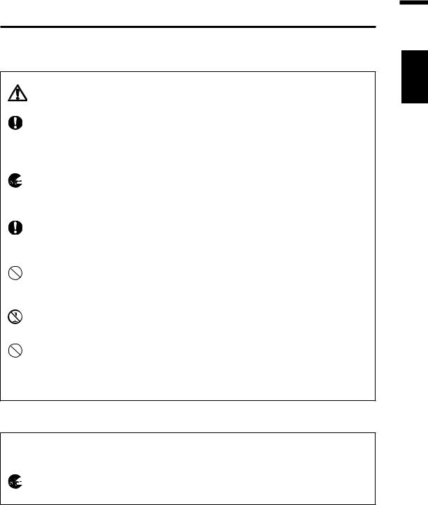
Safety Symbols
The following symbols are used in this manual to prevent accidents which may occur as a result of incorrect use of the instrument.
Denotes a sentence regarding a safety warning or note. Read the sentence carefully to ensure safe and correct use.
Denotes a prohibited operation.
The operation must never been performed.
Denotes an instruction.
The instruction must be strictly adhered to.
Denotes an instruction.
Disconnect the AC adapter from the AC outlet.
Denotes a prohibited operation.
Never disassemble the instrument.
Notes on This Manual
Copying or reproduction of all or any part of the contents of this manual without KONICA MINOLTA's permission is strictly prohibited.
The contents of this manual are subject to change without prior notice.
Every effort has been made in the preparation of this manual to ensure the accuracy of its contents. However, should you have any questions or find any errors, please contact the nearest KONICA MINOLTA-authorized service facility.
KONICA MINOLTA will not accept any responsibility for consequences arising from the use of the instrument.
Safety Precautions
To ensure correct use of this instrument, read the following points carefully and adhere to them. After you have read this manual, keep it in a safe place where it can be referred to anytime a question arises.
Warning (Failure to adhere to the following points may result in death or serious injury.)
Do not use this instrument in places where flammable or combustible gases (gasoline etc.) are present.
Doing so may cause fire.
Always use the AC adapter and power cord supplied as a standard accessory or optional (AC-A312), and connect it to indoor AC outlet of rated voltage and frequency (100 - 120 V  or 200 - 240 V
  , 50/60Hz). Failure to follow either of these may result in damage to unit, fire or electric shock.
If this instrument is not used for a long time, disconnect AC adapter from AC outlet. Accumulated dirt or water on prongs of AC adapter plug may cause fire and should be removed.
Do not forcibly pull any part on power cord when unplugging since this may cause fire or electric shock. Gently disconnect by holding plug. Also, do not handle power cord with wet hands. Doing so may cause electric shock.
Do not forcibly bend, twist or pull power cord. Also, do not place heavy object on power cord, or damage or modify one. Any of these may cause fire or electric shock due to damage to power cord.
Do not disassemble or modify this instrument or AC adapter. Doing so may cause fire or electric shock.
Do not spill liquid on this instrument or drop metal into this instrument. Should either of these happen, switch power off, unplug AC adapter immediately and contact the nearest KONICA MINOLTA authorized service facility.
Should this instrument or AC adapter be damaged or smoke or odd smell be generated, do not keep using such instrument or AC adapter without correction. Doing so may cause fire. In such situations, switch power off immediately, unplug AC adapter and contact the nearest KONICA MINOLTA authorized service facility.
Do not look at sun or intense light through finder of this instrument. This may lose your sight.
Caution (Failure to adhere to following points may result in injury or damage to this instrument or other property.)
Use this instrument near AC outlet for easy plugging or unplugging in using AC adapter.
Do not place this instrument on unstable or sloping surface which may drop or overturn it. Dropping or overturning may injure someone around. Take care not to drop this instrument when carrying it.
Do not move while looking inside finder since this would fall or injure user.
Take special care in handling the ND filter or closeup lens included in the optional accessories. Breakage of the ND filter or closeup lens may injure someone around.

Introduction
This instrument is a high-accuracy spectroradiometer designed to measure luminance and chromaticity up to super-low luminance regions. Carefully read this manual before using one.
Packaging material
Be sure to save all packaging materials (corrugated cardboard boxes, pads and plastic bags) supplied with the purchase. This is delicate measurement instrument. Use packaging materials supplied in purchasing in case this instrument needs to be transferred for such purpose as maintenance in KONICA MINOLTA's factories. These packaging materials are useful for minimizing shock or vibration to this instrument in such situation.
Should any of these packaging materials be lost or broken, please contact the nearest KONICA MINOLTA authorized service facility.
Note on Use
Operating Environment
The standard AC adapter (AC-A312) of this instrument is designed specifically for use indoors. Do not use it outdoors.
Do not disassemble this instrument for being composed of delicate electronic components.
Use this instrument at rated voltage of 100 V - 120 V  or 200 V - 240 V
  (50/60Hz). Connect AC power cord to AC outlet with rated voltage and frequency. Connected voltage should not be outside the range of ±10% of nominal.
This instrument is classified into a Pollution Degree 2 as instrument used in mainly in manufacturing plant, laboratory, warehouse or equivalents. Use this instrument in metal dust free and non condensing potential environment.
This instrument is categorized into Installation Category II as equipment connected to commercially available power source.
Connect PC for controlling this instrument to the outlet with protective grounding. Failure to follow this may result in electric shock due to short circuit.
Take care not to enter foreign substance like water or metal in this instrument. Operating in such state cause serious danger.
Do not use this instrument under direct sunlight or near heater. The internal temperature of this instrument to becomes much higher than ambient temperature which may break this instrument. Also, use this instrument in a well-ventilated place. To ensure proper heat dissipation, keep the ventilation holes free from obstructions.
Avoid rapid change in ambient temperature which may form dew condensation.
Avoid using this instrument in extremely dusty or humid place.
Use the CS-2000 at ambient temperature between 5 and 35ºC and relative humidity 80% or less (at 35ºC) with no condensation. Use the CS-2000A at ambient temperature between 5 and 30ºC and relative humidity 80% or less (at 30ºC) with no condensation. Operating this instrument outside specified temperature and humidity range may not satisfy its original performance.

This Instrument
Do not subject this instrument to strong impact or vibration.
Do not forcibly pull, bend, or apply strong force to power cord for attached AC adapter or USB cable. This may result in snapping.
Connect this unit to power source with minimal noise.
Do not measure a high-luminance light source (including sunlight) beyond the measurement range. The failure to observe this warning could result in damage to the optical system.
Should breakage or abnormality be found during operation, switch power off immediately and unplug. Then refer to “Error Check” on page 82.
Should this instrument break down, do not try to disassemble and repair it by yourself. Please contact the nearest KONICA MINOLTA authorized service facility.
Warm this instrument up for 20 minutes at least after switching power on when the object luminance is 2 cd/m2 or lower (measuring angle 1º).
Objective lens, ND filter and Closeup lens (Optional Accessories)
Make sure that surfaces of objective lens, ND filter or closeup lens are clear. Correct measurement may not be performed if there is dirt, dust, hand soil or part left unclean.
Do not touch surface of objective lens, ND filter or closeup lens with hand.
Do not change ambient temperature rapidly under high humidity. This may mist objective lens, ND filter or closeup lens, resulting in incorrect measurement.
Note on Storage
Body
Do not store this instrument under direct sunlight or near heater. The internal temperature of this instrument becomes much higher than ambient temperature which may break this instrument.
Store this instrument at ambient temperature between 0 and 35ºC and relative humidity 80% or less (at 30ºC) with no condensation. Storage under high temperature and humidity may deteriorate performance of this instrument. For added safety, we recommend storage with such drying agent at room temperature.
Take care not to form condensation. Avoid rapid change in ambient temperature when transferring body for storage.
Put the body in a packaging box supplied when purchased or the storage case (CSA30) in the optional accessories to store in safe place.
Objective lens
For storage, cover the objective lens with standard accessory lens cap.

Cleaning
Body
If this unit becomes dirty, wipe with dry and soft cloth. Do not use organic solvent like benzine or thinner and other chemical agent for cleaning. Should none of these methods be helpful, please contact the nearest KONICA MINOLTA authorized service facility.
Objective lens
Should it be gotten dirt or dust, wipe off with dry and soft cloth or lens cleaning paper. Do not use organic solvent like benzine or thinner and other chemical agent for cleaning. Should none of these methods be helpful, please contact the nearest KONICA MINOLTA authorized service facility.
Notes on Transfer
Use packaging material supplied when purchased to minimize vibration or shock generated during transfer.
Put all material including unit and accessories in original packaging material when returning this instrument for service.
Maintenance
Periodical checkup is recommended annually to maintain measurement accuracy of instrument. For details on checkup, please contact the nearest KONICA MINOLTA authorized service facility.
Disposal Method
Make sure that the CS-2000/CS-2000A, its accessories and the packing materials are either disposed of or recycled correctly in accordance with local laws and regulations.

Contents
Safety Precautions… ………………… 1
Introduction…………………………… 3
Note on Use… …………………………… 3
Operating Environment………………………… 3
This Instrument… ……………………………… 4
Objective lens, ND filter and Closeup lens (Optional Accessories)… ……………………… 4
Note on Storage… ……………………… 4
Body… …………………………………………… 4
Objective lens… ………………………………… 4
Cleaning… ………………………………… 5
Body… …………………………………………… 5 Objective lens… ………………………………… 5
Notes on Transfer………………………… 5 Maintenance… …………………………… 5 Disposal Method… ……………………… 5
Standard Accessories………………… 8
Optional Accessories… ……………… 9
System Configuration… ……………… 11
Names and Functions of Parts… …… 12
Names of Each Part……………………… 12 Functions of Each Part… ……………… 13 Key Panel… ……………………………… 14 Main Functions of Each Key…………… 14 Diopter Adjustment……………………… 15 LCD Screen… …………………………… 16
MEAS (Measurement value) screen… …… 16 MENU screen… ……………………………… 17
Installation
Installing… ……………………………… 20
Connecting AC Adapter… …………… 21
Connection Method……………………… 22
Power Switch ON( | )/OFF(O)………… 23
Turning power switch ON… …………… 23 Turning power switch OFF…………… 23
Setting
Setting of Synchronization…………… 26 Selecting Measurement Time……… 29 Setting Observer… …………………… 35 Selecting Display Format… ………… 37 Selecting Color Space………………… 39
Selecting Absolute Value (ABS)/ Difference (DIFF) Display… ………… 41
When Using Closeup Lens…………… 43 When Using ND Filter… ……………… 45 Calibration… …………………………… 47
Calibration Channel……………………… 47
Backlight ON/OFF During Measurement… ………………………… 49
Measurement
Measurement… ………………………… 52
Saving the Measurement Value……… 55
Deleting the Memory Data… ………… 58
Registering Target Color……………… 61
Target color… …………………………… 61
Selecting Target Color………………… 65
Deleting Target Color… ……………… 67
Communication
Connecting to PC… …………………… 72 Remote Mode…………………………… 73
Explanation
Measurement Principle… …………… 76
Sensor Section… …………………………… 76
Dark Measurement… ………………… 76
LvT uv… ………………………………… 77
Dominant wavelength/Excitation purity…… 78
Measurement of Object Color… …… 79
Necessary Setting for Object Color Measurement…… 79 White Calibration……………………………… 79 Measurement of Object……………………… 79
Dimensions……………………………… 80
Error Message… ……………………… 81
Error Check……………………………… 82
Setting Initialization… ………………… 85
Switching Luminance Unit… ………… 86
Main Specifications… ………………… 87
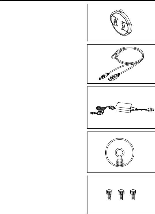
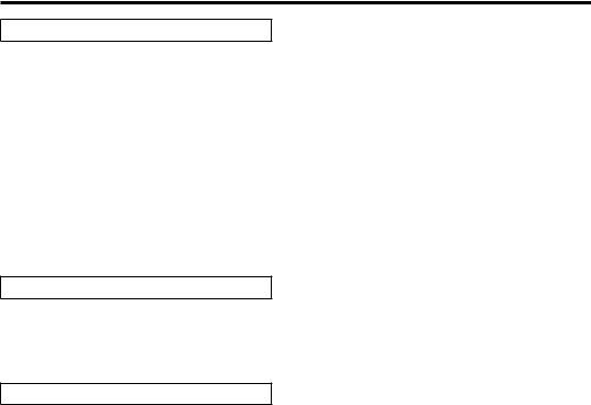
Standard Accessories
Lens Cap CS-A31
Attached to objective lens for protecting it when not using this instrument.
USB Cable (2 m) CS-A32
Used for communication between this instrument and PC.
AC Adapter AC-A312
Supplies power from AC outlet.
Input: 100 - 120 V  or 200 - 240 V
0.75 - 0.42 A
50/60 Hz
Output: 12 V  3 A
3 A
Data Management Software
CS-S10w Professional
Software to control this instrument from PC for various data management.
The protect key is attached.
Screw for focus ring lock CS-A38
Locks the focus adjustment ring of the CS- 2000/CS-2000A so that it does not move unintentionally and change the focus.
·Do not use any screw except for the attached screw. Should it be lost or damaged, purchase a new CS-A38.
·When storing the CS-2000/CS-2000A in the Storage Case (optional accessory), remove the screw.
·When storing the CS-2000/CS-2000A in the packing box for transfer, remove the screw.
Optional Accessories
Calibration Certificate
ND Eyepiece Filter CS-A1
Reduces glare during observation through the finder when a high-luminance object is measured. Be sure to place this filter in front of the finder when measuring highluminance objects.
ND Filter (1/10) CS-A33
ND Filter (1/100) CS-A34
Placed in front of objective lens for measurement of high luminance object.
Calibration Certificate (for ND filter)
Calibration certificates can be attached to the ND filters (1/10) CS-A33 and (1/100) CSA34.
Closeup Lens CS-A35
Placed in front of objective lens for measurement of small object.
Adapter for CCD camera CS-A36
Placed between the finder and the body when a C-mount industrial camera is used.
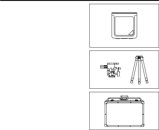
White Calibration Plate CS-A5 (without data) White Calibration Plate CS-A5 (with data) White Calibration Plate CS-A5 (with data and calibration certificate)
Used for measurement of object colors. Three types (named, not-named, named with calibration certificate) are prepared.
Tripod CS-A3
Pan Head CS-A4
Used when installing this instrument.
Storage Case CS-A30
Used to house the instrument and accessories or to carry them by hand. Never use this as a transport case.
10
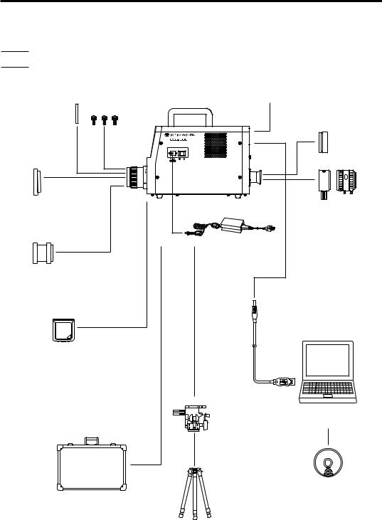
System Configuration
Standard Accessories
Optional Accessories
Screw for
Lens Cap focus ring lock
CS-A38
ND Filter (1/10) CS-A33 (1/100) CS-A34
Calibration Certificate (for ND filter)
Closeup Lens
CS-A35
CS-2000 Main Unit Calibration Certificate
ND Eyepiece Filter
CS-A1
Adapter
for CCD camera
CS-A36
AC Adapter
AC-A312
USB Cable (2 m)
CS-A32
White Calibration Plate
CS-A5 (w/o data)
CS-A5 (w/ data)
CS-A5 (w/ data and calibration certificate)
Pan Head
CS-A4
PC
(on the market)
|
Tripod |
|
|
CS-A3 |
Data Management |
|
|
|
Storage Case |
|
Software |
|
CS-S10w Professional |
|
CS-A30 |
|
|
|
|
11

Names and Functions of Parts
Names of Each Part
(7) Focus distance scale |
Handle |
(6) Focus
adjustment ring
(1) Power switch
(2) AC adapter input terminal
(5) Objective lens |
(14) Screw holes for fixing |
|
(8) LCD screen
(10) Measurement
button
(3) USB connector
(9) Key panel
|
(15) Vertically |
(12) Diopter |
synchronized |
signal input |
|
adjustment ring |
terminal |
Inside finder |
(4) Measuring |
|
angle selector |
(13) Aperture |
|
|
(11) Finder |
12

Functions of Each Part
(1) Power switch |
Switches this instrument on/off. ( | ) for ON; (O) for OFF.……(p.23) |
(2)AC adapter input terminal Connects the attached AC adapter.… ……………………… (p.21)
(3)USB connector Connects the USB cable when connecting to PC.… ………(p.72)
(4)Measuring angle selector Selects measurement angle among 1º, 0.2º and 0.1º.…………(p.52)
(5)Objective lens Directed to object for measurement.… ………………………(p.53)
(6)Focus adjustment ring Adjusts focus of objective lens before measurement.………(p.53)
(7)Focus distance scale Helps adjusting focus.… ………………………………………(p.53)
(8) LCD Screen |
Displays various screens like measurement and menu.… … (p.16) |
||||||
(9) Key Panel |
Offers several keys for operation of this instrument.… …… (p.14) |
||||||
(10)Measurement button |
For measurement.………………………………………………(p.53) |
||||||
(11) Finder |
Used to observe object for measurement.… ………… (p.15, 53) |
||||||
(12) Diopter adjustment ring |
Adjusts diopter.… ………………………………………… (p.15, 53) |
||||||
(13)Aperture |
Indicates measuring area.… …………………………………(p.53) |
||||||
|
Size of black circle will change depending on measuring angle. |
||||||
|
|
|
|
|
|
|
|
|
|
|
|
|
|
|
|
|
1º Aperture |
0.2º Aperture |
0.1º Aperture |
|
(14) Screw holes for fixing |
Used to fix this instrument with tripod or jig.… |
…………… |
(p.20) |
|
(15) Vertically synchronized |
Connects the cable to input the vertically synchronized |
|
||
signal input terminal |
signal or the external sync measurement.… ……………… |
(p.26) |
||
13
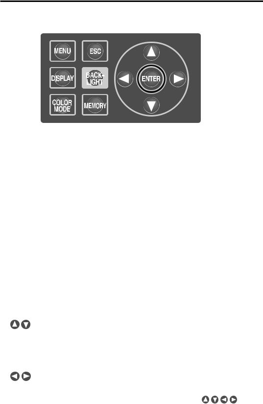
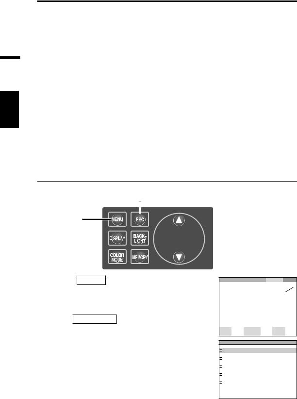
Key Panel
(1) |
(4) |
(7) |
|
|
(2) (5)
(5)
(3) |
(6 ) |
Main Functions of Each Key
(1) MENU key |
The MENU screen appears if this key pressed when the |
|
measurement value screen appears. (p.17) |
(2) DISPLAY key |
Selects whether chromaticity is displayed in absolute value (ABS) or difference |
|
(DIFF) if this key pressed when the measurement value screen appears. (p.41) |
(3) COLOR MODE key Color space modes are switched in turn as follows, by pressing
|
the key when the measurement value screen appears: Lvxy |
|
Lvu’v’ LvT uv XYZ Dominant wavelength/Excitation purity |
|
Spectral graph Lvxy. (p.39) |
(4) ESC key |
If this key is pressed when the MENU screen is displayed, the |
|
settings are canceled and the measurement value screen |
|
appears again. If pressed during numerical input or when making |
|
each setting, the settings are canceled. If pressed during |
|
continuous measurement, the measurement ends. |
(5)BACKLIGHT key Selects backlight ON/OFF on LCD screen. (p.49)
(6)MEMORY key Measured data is stored in memory by pressing this key when the
measurement value screen appears. (p.55)
(7) |
keys |
Memory data, target color channels, calibration channels, etc., |
|
|
|
are changed by pressing the key when the screen for display of |
|
|
|
various data appears. The cursor position is moved up and |
|
|
|
down, or the values and set items are changed, by pressing the |
|
|
|
key during numerical input or when making each setting. |
|
|
keys |
The cursor position moves right and left by pressing the key for |
|
|
|
numerical input or when making each setting. |
|
|
ENTER key |
Press the key to fix the contents selected in |
. |
14
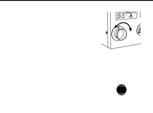
Diopter Adjustment
Rotate the diopter adjustment ring for adjustment of diopter.
Diopter 
 adjustment ring
Adjust so that A or B on aperture or black circle |
|
indicating measuring area looks clear when |
|
observing object through finder. |
|
Adjustment would be easy starting with 1º |
A |
aperture where object near aperture looks blur. |
|
Make sure to adjust diopter before |
B |
|
|
measurement. Diopter should be adjusted for |
|
the eyesight of the person who will be taking |
|
measurement. If diopter is not adjusted before |
|
|
|
focus measurement, correct measurement value |
|
may not be expected. This is because the focus |
|
is actually off even if you think it is correctly in |
|
focus. In addition, if diopter is not correctly |
|
adjusted, you may see the aperture moving |
|
depending on viewing angle. |
|
* You sometimes see small black dots or stripes |
|
in internal finder. It gives no effect on |
|
measuring performance. |
|
15

LCD Screen
MEAS (Measurement value) screen
“SNGL” is displayed for the |
|
|
Calibration channel (p.47) Target color channel |
|||||||||||
values obtained during single |
|
|
|
|
|
|
|
(p.61, 65, 67) |
||||||
|
|
|
|
|
|
|||||||||
measurement, while “CONT” |
|
|
|
|
|
|
|
|
|
|||||
|
|
|
|
|
|
|
|
|
||||||
is displayed for the values |
|
|
|
|
|
|
|
|
|
|||||
|
|
|
|
|
|
|
|
|
||||||
obtained during continuous |
|
|
|
|
|
|
|
|
|
|||||
measurement. (p.53) |
|
|
|
|
|
|
|
|
|
|||||
|
|
|
|
|
|
|
|
|
||||||
|
|
|
|
|
|
|
|
|
|
|
|
|
||
|
MEAS |
|
SNGL |
|
UC00 |
|
T01 |
|
Measurement result is displayed in the |
|||||
|
Lv |
80. 00 |
|
cd |
|
|||||||||
|
|
|
currently selected color space. |
|||||||||||
|
|
|
|
|
|
|||||||||
|
x |
0 . 0000 |
|
|
|
|
|
|
(Lvxy, Lvu’v’, LvT uv, XYZ, Dominant |
|||||
|
|
|
|
|
|
|
wavelength/Excitation purity, Spectral |
|||||||
|
y |
|
|
|
|
|
|
|
|
|
graph) (p.39) |
|||
|
0 . 0000 |
|
|
|
|
|
|
Display format can be changed. (p.37) |
||||||
|
|
SPD |
|
LEN |
|
BL |
|
|
|
|||||
|
Obs |
SYNC |
ND |
|
Setting status in this instrument is |
|||||||||
|
10˚ |
M-N |
Non |
C-U |
100 |
on |
|
|||||||
|
||||||||||||||
displayed.
|
<SPD> |
|
|
<Obs> |
<SYNC> |
||
Currently selected |
Currently selected |
“Int” is displayed when |
|
observer angle is |
measuring time is |
the internal sync |
|
displayed. |
displayed. |
measurement mode is |
|
(2°,10°) (p.35) |
(Nrm, Fst, M-N, M-F, |
set. “Ext” is displayed |
|
|
Mnl) (p.29) |
when the external sync |
|
|
|
measurement mode. |
|
|
|
“Non” is displayed when |
|
|
|
the sync measurement |
|
|
|
mode is not set. (p.26) |
|
16

MENU screen
The MENU screen appears if MENU key is pressed when the measurement value screen
is displayed.
MENU
MEAS
MEMORY
TARGET
OP T I ON
S E T U P
MEAS
Used to set measurement time or synchronizing method. (p.26, 29)
MEMORY
Used to read or delete the measurement memory data. (p.56, 58)
TARGET
Used to register, select or delete the target color. (p.61, 65, 67)
OPTION
Used to set the closeup lens, ND filter or calibration channel. (p.43, 45, 47)
SETUP
Used to set the observer, backlight or display format. (p.35, 49, 37)
<LENS> |
<ND> |
<BL> |
“C-U” is displayed, if the |
The current ND filter type |
“On” is displayed, if the |
closeup lens is attached. |
is displayed. |
backlight is set to be |
If not, “Std” is displayed |
(Non, 10, 100) (p.45) |
turned on during the |
(p.43). |
|
measurement. “Off” is |
|
|
displayed, if the backlight |
|
|
is set to be turned off |
|
|
during that time. (p.49) |
17
18
Installation
19
Installation
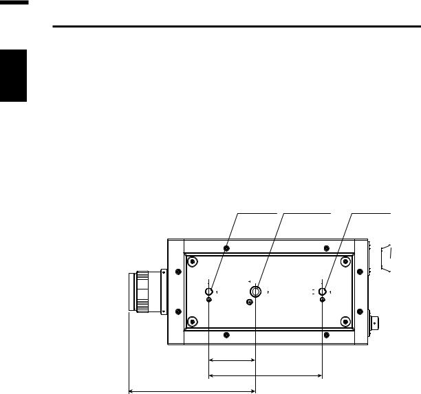
Installing
Use screw holes for fixing at the bottom of this instrument if utilized with the tripod or jig. 2-type holes are available.
Tripod screw hole: To set on the tripod. Use a tripod screw with top diameter of 3/8 inches and depth of 10.5 mm.
[Note] The tripod screw holes correspond with the 3/8-inch screws of a large camera tripod. 1/4-inch screws cannot be used for fixing this instrument.
ISO screw hole: To set on the jig. Use ISO screws with top diameter of 5 mm and depth of 6.5 mm.
Measurement distance |
ISO screw Tripod screw |
ISO screw |
||||
reference |
|
|
|
|
|
|
|
|
|
|
|
|
|
|
|
|
|
|
|
|
Optical 


 axis
axis 
70
170
190.4
For other detailed dimensions, see p.80.
20
Connecting AC Adapter
The AC adapter supplied with this instrument is used for the corresponding power source.
Warning |
(Failure to adhere to the following points may result in death or serious injury.) |
Always use the AC adapter and power cord supplied as a standard accessory or optional accessory (AC-A312), and connect it to indoor AC outlet of rated voltage and frequency (100 - 120 V  or 200 - 240 V
  , 50/60Hz). Failure to follow either of these may result in damage to unit, fire or electric shock.
If this instrument is not used for a long time, disconnect AC adapter from AC outlet. Accumulated dirt or water on prongs of AC adapter plug may cause fire and should be removed before use.
Do not forcibly pull any part on power cord when unplugging since this may cause fire or electric shock. Gently disconnect by holding plug. Also, do not handle power cord with wet hands. Doing so may cause electric shock.
Do not forcibly bend, twist or pull power cord. Also, do not place heavy object on power cord, or damage or modify one. Any of these may cause fire or electric shock due to damage to power cord.
Do not disassemble or modify this instrument or AC adapter. Doing so may cause fire or electric shock.
Should this instrument or AC adapter be damaged or smoke or odd smell be generated, do not keep using such instrument or AC adapter without correction. Doing so may cause fire. In such situations, switch power off immediately, unplug AC adapter and contact the nearest KONICA MINOLTA authorized service facility.
 Caution (Failure to adhere to following points may result in injury or damage to this instrument or other property.)
Use this instrument near AC outlet for easy plugging or unplugging in using AC adapter.
Installation
21
Installation
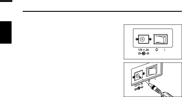
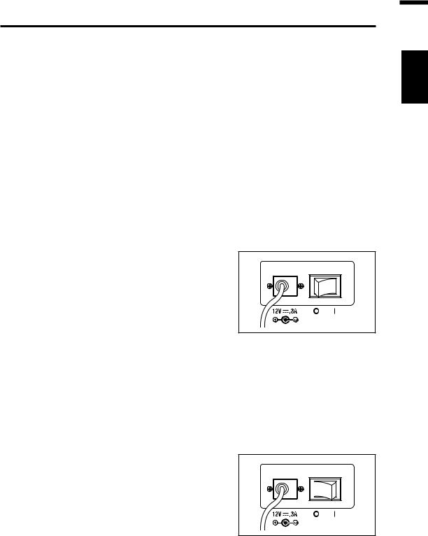
Connection Method
1. Make sure that power switch is OFF (slided to [O] side).
2. Connect the AC adapter plug to the AC adapter input terminal of the body.
3. Plug the AC adapter to outlet (100 - 120 VAC  or 200 - 240 VAC
  , 50 Hz/60 Hz).
Insert the AC adapter plug all the way seated in AC outlet.
22
Power Switch ON( | )/OFF(O)
The warm-up time needed is a minimum of 20 minutes in order to measure the objects with excellent accuracy under the conditions described below. Warm up this instrument for 20 or more minutes when the power source is turned off even for a short period, and turned on again.
(1) The object is a low-luminance light source, using 2856 K (standard light source A) as a guide: 2 cd/m2 or lower (1° Aperture)
50 cd/m2 or lower (0.2° Aperture)
200 cd/m2 or lower (0.1° Aperture)
(2) Outside room temperature and normal humidity ranges
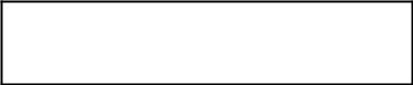
Turning power switch ON
1. Slide power switch to ON ( | ) side.
The measurement screen appears 5 seconds after the initial screen on the LCD.
The model type (CS-2000 or CS2000A), body version and product serial numbers are displayed on the initial screen. The model type can be also confirmed on the nameplate.
Turning power switch OFF
2. Slide power switch to OFF (O side) after measurement.
Installation
23
24
Setting
25
Setting
Setting of Synchronization
The synchronized measurement refers to measurement mode where measurement is made in the same timing as periodical light source pulse frequency, such as vertically synchronized frequency for the display device.
[INT SYNC]
The internal sync measurement mode is used to measure the display equipment without the input of vertically synchronized signals to the body, or to measure flicker light from a light source such as a fluorescent light. Input the frequency of vertically synchronized signals for the display equipment, or the commercial frequency (50 or 60 Hz) for flicker light from a light source such as a luminescent light. The optimal integration time is automatically set based on the input value and the brightness of the object. For this reason, enter the correct frequency value to two places of decimals.
However, if the vertically synchronized frequency of the display equipment is not clear, accurate measurement will not be possible with an inaccurate frequency setting. In this case it is recommended to select [NO SYNC] mode without sync measurement (at 60 Hz of frequency), but to select [MULTI-NORMAL] mode or [MULTI-FAST] mode for the measurement time (refer to p. 29).
[EXT SYNC]
The external sync measurement mode is used to measure the display equipment after the line input of a vertically synchronized signal through the input terminal for vertically synchronized signals to the body. The optimal integration time is set automatically, based on the frequency of vertically synchronized signals and the brightness of the object.Input CMOS (5V) Level of the input signals.
* Range of synchronized frequencies : 20.00 to 200.00 Hz
* Factory default setting : NO SYNC
Operation Procedure
6, 7
1


 2, 3, 4, 5
1. Press MENU key when the MEAS screen is displayed.
The MENU screen appears.
When the backlight of the LCD has been turned off via BACKLIGHT key on the MEAS screen,
the backlight is turned on.
 MEAS SNGL
 UC00 T01
Lv |
35. 93 |
cd |
|
|
x0 . 3968
y0 . 4060
Obs SPD SYNC LEN ND BL 2˚ Nrm Non S t d Non on
MENU
MEAS
MEMORY
TARGET
OPTION
SETUP
26
Loading...