


CH18-745

COMMAND CH18-745
HORIZONTAL CRANKSHAFT
SERVICE MANUAL
Safety and General Information
Section 1
Safety and General Information
Safety Precautions
To ensure safe operation please read the following statements and understand their meaning. Also
refer to your equipment manufacturer's manual for other important safety information. This manual
contains safety precautions which are explained below . Please read carefully.
WARNING
Warning is used to indicate the presence of a hazard that can cause severe personal injury, death,
or substantial property damage if the warning is ignored.
CAUTION
Caution is used to indicate the presence of a hazard that will or can cause minor personal injury or
property damage if the caution is ignored.
Section 1
CH18-745
1
NOTE
Note is used to notify people of installation, operation, or maintenance information that is important
but not hazard-related.
For Y our Safety!
These precautions should be followed at all times. Failure to follow these precautions could result in
injury to yourself and others.
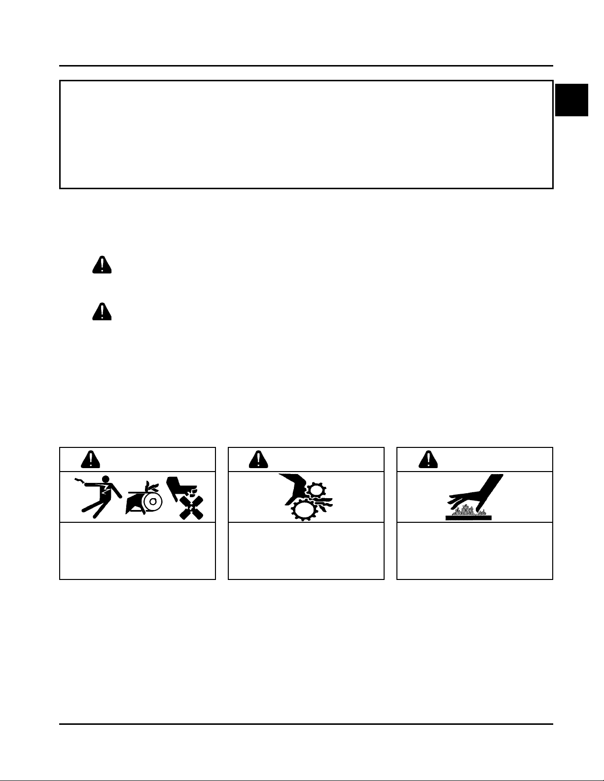
WARNING
Accidental Starts can cause
severe injury or death.
Disconnect and ground spark plug
leads before servicing.
Accidental St arts!
Disabling engine. Accidental
starting can cause severe injury
or death. Before working on the
engine or equipment, disable the
engine as follows: 1) Disconnect the
spark plug lead(s). 2) Disconnect
negative (-) battery cable from
battery .
WARNING
Rotating Parts can cause severe
injury.
Stay away while engine is in
operation.
Rotating Part s!
Keep hands, feet, hair, and
clothing away from all moving
parts to prevent injury. Never
operate the engine with covers,
shrouds, or guards removed.
Hot Parts can cause severe burns.
Do not touch engine while operating
or just after stopping.
Hot Parts!
Engine components can get
extremely hot from operation. To
prevent severe burns, do not
touch these areas while the
engine is running - or immediately
after it is turned off. Never operate
the engine with heat shields or
guards removed.
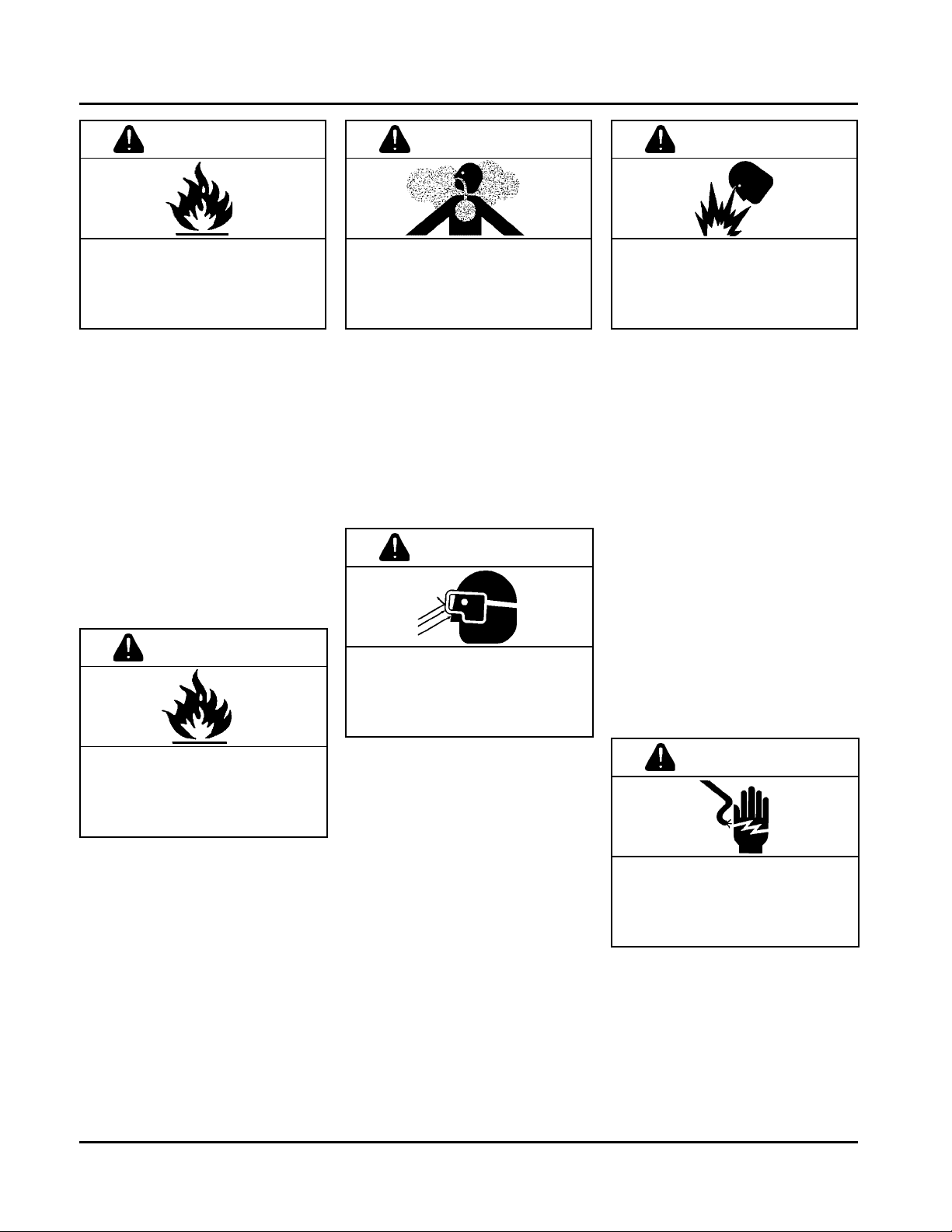
WARNING
1.1
Section 1
Safety and General Information
WARNING
Explosive Fuel can cause fires and
severe burns.
Stop engine before filling fuel tank.
Explosive Fuel!
Gasoline is extremely flammable
and its vapors can explode if
ignited. Store gasoline only in
approved containers, in well
ventilated, unoccupied buildings,
away from sparks or flames. Do not
fill the fuel tank while the engine is
hot or running, since spilled fuel
could ignite if it comes in contact
with hot parts or sparks from
ignition. Do not start the engine
near spilled fuel. Never use
gasoline as a cleaning agent.
WARNING
WARNING WARNING
Carbon Monoxide can cause
severe nausea, fainting or death.
Do not operate engine in closed or
confined area.
Lethal Exhaust Gases!
Engine exhaust gases contain
poisonous carbon monoxide.
Carbon monoxide is odorless,
colorless, and can cause death if
inhaled. Avoid inhaling exhaust
fumes, and never run the engine
in a closed building or confined
area.
WARNING
Uncoiling Spring can cause severe
injury.
Wear safety goggles or face
protection when servicing retractable
starter.
Explosive Gas can cause fires and
severe acid burns.
Charge battery only in a well
ventilated area. Keep sources of
ignition away.
Explosive Gas!
Batteries produce explosive
hydrogen gas while being
charged. To prevent a fire or
explosion, charge batteries only in
well ventilated areas. Keep
sparks, open flames, and other
sources of ignition away from the
battery at all times. Keep batteries
out of the reach of children.
Remove all jewelry when servicing
batteries.
Before disconnecting the negative
(-) ground cable, make sure all
switches are OFF. If ON, a spark
will occur at the ground cable
terminal which could cause an
explosion if hydrogen gas or
gasoline vapors are present.
Cleaning Solvents can cause
severe injury or death.
Use only in well ventilated areas
away from ignition sources.
Flammable Solvents!
Carburetor cleaners and solvents
are extremely flammable. Keep
sparks, flames, and other sources
of ignition away from the area.
Follow the cleaner manufacturer’s
warnings and instructions on its
proper and safe use. Never use
gasoline as a cleaning agent.
1.2
Spring Under T ension!
Retractable starters contain a
powerful, recoil spring that is under
tension. Always wear safety
goggles when servicing retractable
starters and carefully follow
instructions in the "Retractable
Starter" Section 7 for relieving
spring tension.
CAUTION
Electrical Shock can cause injury.
Do not touch wires while engine is
running.
Electrical Shock!
Never touch electrical wires or
components while the engine is
running. They can be sources of
electrical shock.
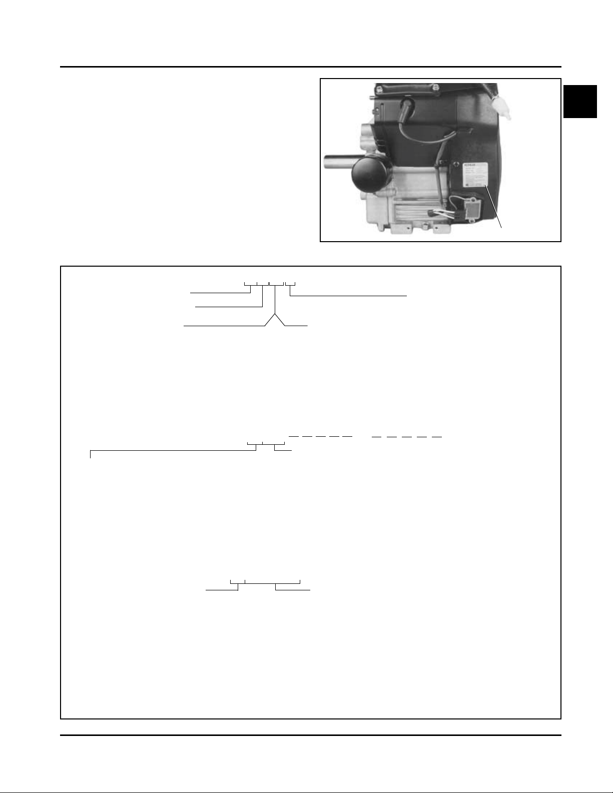
Engine Identification Numbers
When ordering parts, or in any communication
involving an engine, always give the Model,
Specification and Serial Numbers, including letter
suffixes if there are any.
The engine identification numbers appear on a decal,
or decals, affixed to the engine shrouding. See Figure
1-1. An explanation of these numbers is shown in
Figure 1-2.
Section 1
Safety and General Information
1
Identification Decal
Figure 1-1. Engine Identification Decal Location.
A. Model No.
Command Engine
Horizontal Crankshaft
Numerical Designation
730
740
745
B. Spec. No.
Engine Model Code
Code Model
62 CH18
64 CH20
66 CH22 (624 cc)
68 CH25
76 CH22/23 (674 cc)
78 CH26
C H 18 S
or
62500
Horsepower
17 = 17 HP
18 = 18 HP
20 = 20 HP
22 = 22 HP
23 = 23 HP
25 = 25 HP
26 = 26 HP
Variation of
Basic Engine
or
Version Code
S = Electric Start
CH730-0001
CH740-0001
CH745-0001
Complete Spec Number
(Incorporating Model
No. with V ariation No. of
Basic Spec.)
C. Serial No.
Year Manufactured Code
Code Year
21 1991
22 1992
23 1993
24 1994
25 1995
26 1996
27 1997
28 1998
29 1999
Figure 1-2. Explanation of Engine Identification Numbers.
3305810334
Factory Code
Code Year
30 2000
31 2001
32 2002
33 2003
34 2004
35 2005
1.3
Section 1
Safety and General Information
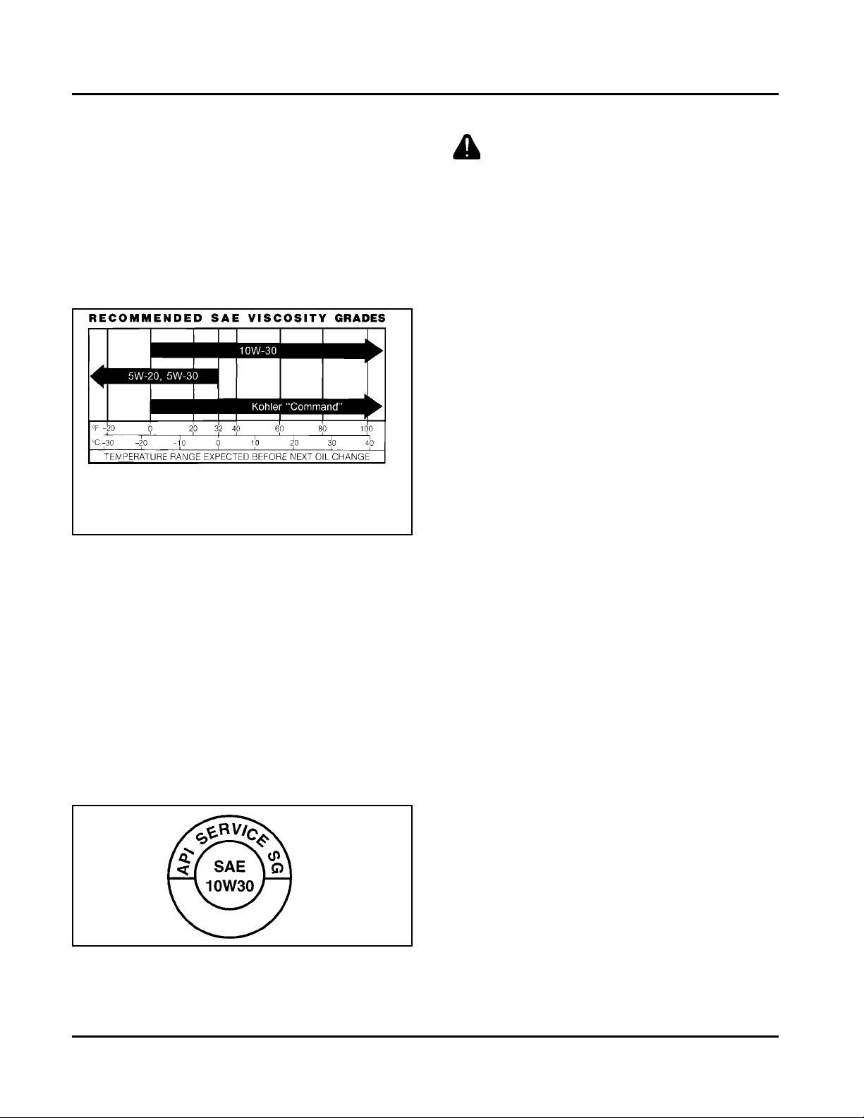
Oil Recommendations
Using the proper type and weight of oil in the crankcase
is extremely important. So is checking oil daily and
changing oil regularly . Failure to use the correct oil, or
using dirty oil, causes premature engine wear and failure.
Oil Type
Use high-quality detergent oil of API (American
Petroleum Institute) Service Class SG, SH, SJ or
higher. Select the viscosity based on the air temperature
at the time of operation as shown in the following table.
**
*
*Use of synthetic oil having 5W-20 or 5W-30 rating is
acceptable, up to 40°F.
**Synthetic oils will provide better starting in extreme
cold (below -10°F).
NOTE: Using other than service class SG, SH, SJ or
higher oil or extending oil change intervals
longer than recommended can cause engine
damage.
NOTE: Synthetic oils meeting the listed classifications
may be used with oil changes performed at the
recommended intervals. However, to allow
piston rings to properly seat, a new or rebuilt
engine should be operated for at least 50 hours
using standard petroleum based oil before
switching to synthetic oil.
A logo or symbol on oil cont ainers identifies the API
service class and SAE viscosity grade. See Figure 1-3.
Fuel Recommendations
WARNING: Explosive Fuel!
Gasoline is extremely flammable and its vapors can
explode if ignited. Before servicing the fuel system,
make sure there are no sparks, open flames or other
sources of ignition nearby as these can ignite gasoline
vapors. Disconnect and ground the spark plug leads to
prevent the possibility of sparks from the ignition
system.
General Recommendations
Purchase gasoline in small quantities and store in
clean, approved containers. A cont ainer with a capacity
of 2 gallons or less with a pouring spout is
recommended. Such a container is easier to handle
and helps eliminate spillage during refueling.
Do not use gasoline left over from the previous
season, to minimize gum deposits in your fuel system
and to ensure easy starting.
Do not add oil to the gasoline.
Do not overfill the fuel tank. Leave room for the fuel to
expand.
Fuel Type
For best results, use only clean, fresh, unleaded
gasoline with a pump sticker octane rating of 87 or
higher. In countries using the Research method, it
should be 90 octane minimum.
Unleaded gasoline is recommended as it leaves less
combustion chamber deposits and reduces harmful
exhaust emissions. Leaded gasoline is not
recommended and must not be used on EFI engines,
or on other models where exhaust emissions are
regulated.
Figure 1-3. Oil Container Logo.
Refer to Section 6 - “Lubrication System” for detailed
procedures on checking the oil, changing the oil and
changing the oil filter.
1.4
Gasoline/Alcohol blends
Gasohol (up to 10% ethyl alcohol, 90% unleaded
gasoline by volume) is approved as a fuel for Kohler
engines. Other gasoline/alcohol blends are not
approved.
Gasoline/Ether blends
Methyl T ertiary Butyl Ether (MTBE) and unleaded
gasoline blends (up to a maximum of 15% MTBE by
volume) are approved as a fuel for Kohler engines. Other
gasoline/ether blends are not approved.
Periodic Maintenance Instructions
Section 1
Safety and General Information
WARNING: Accident al Starts!
Disabling engine. Accidental starting can cause severe injury or death. Before working on the engine or
equipment, disable the engine as follows: 1) Disconnect the spark plug lead(s). 2) Disconnect negative (-) battery
cable from battery .
Maintenance Schedule
These required maintenance procedures should be performed at the frequency stated in the table. They should also
be included as part of any seasonal tune-up.
Maintenance Required Refer to:Frequency
• Fill fuel tank. Section 5
Daily or Before
Starting Engine
Every 25 Hours
Every 100 Hours
Every 200 Hours
Every 250 Hours
Annually or
Every 500 Hours
Every 500 Hours
Every 1500 Hours
1
Perform these maintenance procedures more frequently under extremely dusty , dirty conditions.
2
Have a Kohler Engine Service Dealer perform this service.
3
Cleanout Kits 25 755 20-S (black) or 25 755 21-S (gold) allow cooling areas to be cleaned without removing
shrouds.
• Check oil level. Section 6
• Check air cleaner for dirty1, loose, or damaged parts. Section 4
• Check air intake and cooling areas, clean as necessary1. Section 4
• Service precleaner element1. Section 4
• Replace air cleaner element1. Section 4
• Change oil. (More frequently under severe conditions.) Section 6
• Remove cooling shrouds and clean cooling areas
• Check oil cooler fins, clean as necessary (if equipped). Section 6
• Check spark plug condition and gap. Section 8
• Change oil filter. Section 6
• Replace heavy-duty air cleaner element and check inner element1. Section 4
• Have bendix starter drive serviced2. Section 8
• Have solenoid shift starter disassembled and cleaned2. Section 8
• Have crankshaft spline lubricated2. Section 2
• Replace fuel filter1 (EFI engines). Section 5B
1,3
. Section 4
1
Storage
If the engine will be out of service for two months or
more, use the following storage procedure.
1. Clean the exterior surfaces of the engine. On
Electronic Fuel Injected (EFI) engines, avoid
spraying water at the wiring harness or any of the
electrical components.
2. Change the oil and oil filter while the engine is still
warm from operation. See “Change Oil and Oil
Filter” in Section 6.
3. The fuel system must be completely emptied, or
the gasoline must be treated with a stabilizer to
prevent deterioration. If you choose to use a
stabilizer , follow the manufacturer’s
recommendations, and add the correct amount
for the capacity of the fuel system.
Fill the fuel tank with clean, fresh gasoline. Run
the engine for 2 to 3 minutes to get stabilized fuel
into the rest of the system. Close the fuel shut-off
valve when the unit is being stored or transported.
To empty the system, run the engine until the tank
and the system are empty.
4. Remove the spark plugs and add one tablespoon
of engine oil into each spark plug hole. Install the
spark plugs, but do not connect the plug leads.
Crank the engine two or three revolutions.
5. On equipment with an EFI engine, disconnect the
battery or use a battery minder to keep the battery
charged during storage.
6. Store the engine in a clean, dry place.
1.5
Section 1
Safety and General Information
Dimensions in millimeters.
Inch equivalents shown in ().
Figure 1-4. Typical Engine Dimensions CH Series with Standard Flat Air Cleaner.
1.6
Section 1
Safety and General Information
Dimensions in millimeters.
Inch equivalents shown in ().
1
Figure 1-5. T ypical Engine Dimensions CH EFI Series with Heavy-Duty Air Cleaner.
1.7

Section 1
Safety and General Information
General Specifications¹
Power (@ 3600 RPM, corrected to SAE J1995)
CH18............................................................................................................................13.4 kW (18 HP)
CH20............................................................................................................................14.9 kW (20 HP)
CH22/23....................................................................................................................... 16.4 kW (22 HP)
CH25, CH730...............................................................................................................18.4 kW (25 HP)
CH26............................................................................................................................19.4 kW (26 HP)
CH740..........................................................................................................................20.1 kW (27 HP)
CH745..........................................................................................................................20.9 kW (28 HP)
Peak Torque
CH18 - @ 2200 RPM ................................................................................................... 44.4 N·m (32.8 ft. lb.)
CH20 - @ 2600 RPM ................................................................................................... 44.2 N·m (32.6 ft. lb.)
CH22/23 - @ 2200 RPM ..............................................................................................51.7 N·m (38.2 ft. lb.)
CH25, CH730 - @ 2800 RPM ...................................................................................... 54.1 N·m (39.9 ft. lb.)
CH26 - @ 2800 RPM ................................................................................................... 54.2 N·m (40.0 ft. lb.)
CH740 - @ 3000 RPM ................................................................................................. 57.9 N·m (42.7 ft. lb.)
CH745 - @ 2200 RPM ................................................................................................. 60.7 N·m (44.8 ft. lb.)
Bore
CH18, CH20, CH22 (624 cc)........................................................................................ 77 mm (3.03 in.)
CH22/23 (674 cc).........................................................................................................80 mm (3.15 in.)
CH25, CH26, CH730-745.............................................................................................83 mm (3.27 in.)
Stroke.................................................................................................................................67 mm (2.64 in.)
Displacement
CH18, CH20, CH22 (624 cc)........................................................................................ 624 cc (38 cu. in.)
CH22/23 (674 cc).........................................................................................................674 cc (41 cu. in.)
CH25, CH26, CH730-745.............................................................................................725 cc (44 cu. in.)
Compression Ratio
CH18, CH20, CH22/23.................................................................................................8.5:1
CH25, CH26, CH730-745.............................................................................................9.0:1
Dry Weight
CH18, CH20, CH22/23................................................................................................. 41 kg (90 lb.)
CH25, CH26, CH730-745.............................................................................................43 kg (94 lb.)
Oil Capacity (with filter)
CH18, CH20, CH22/23, CH25, CH26, CH730-745 ......................................................1.9 L (2.0 U.S. qt.)
Angle of Operation - Maximum (At Full Oil Level) All Directions ......................................... 25°
Blower Housing and Sheet Metal
M5 Fasteners Torque..........................................................................................................4.0 N·m (35 in. lb.)
M6 Fasteners Torque..........................................................................................................6.8 N·m (60 in. lb.)
Rectifier-Regulator Fastener Torque...................................................................................4.0 N·m (35 in. lb.)
¹V alues are in Metric units. V alues in parentheses are English equivalents. Lubricate threads with engine oil prior
to assembly.
1.8

Section 1
Safety and General Information
Camshaft
End Play (With Shim) .................................................................................. 0.076/0.127 mm (0.0030/0.0050 in.)
Running Clearance...................................................................................... 0.025/0.063 mm (0.0010/0.0025 in.)
Bore I.D.
New....................................................................................................... 20.000/20.025 mm (0.7874/0.7884 in.)
Max. Wear Limit.................................................................................... 20.038 mm (0.7889 in.)
Camshaft Bearing Surface O.D.
New....................................................................................................... 19.962/19.975 mm (0.7859/0.7864 in.)
Max. Wear Limit.................................................................................... 19.959 mm (0.7858 in.)
Carburetor and Intake Manifold
Intake Manifold Mounting Fastener Torque
Torque in Two Stages............................................................................ initially to 7.4 N·m (66 in. lb.)
finally to 9.9 N·m (88 in. lb.)
Carburetor Mounting Screw Torque M6 ....................................................... 6.2-7.3 N·m (55-65 in. lb.)
1
Adapter (for Heavy Duty Air Cleaner) Mounting Fastener Torque ................ 7.3 N·m (65 in. lb.)
Connecting Rod
Cap Fastener Torque (torque in increments)
8 mm straight shank.............................................................................. 22.7 N·m (200 in. lb.)
8 mm step-down ................................................................................... 14.7 N·m (130 in. lb.)
6 mm straight shank.............................................................................. 1 1.3 N·m (100 in. lb.)
Connecting Rod-to-Crankpin Running Clearance
New....................................................................................................... 0.030/0.055 mm (0.0012/0.0022 in.)
Max. Wear Limit.................................................................................... 0.070 mm (0.0028 in.)
Connecting Rod-to-Crankpin Side Clearance .............................................. 0.26/0.63 mm (0.0102/0.0248 in.)
Connecting Rod-to-Piston Pin Running Clearance ...................................... 0.015/0.028 mm (0.0006/0.001 1 in.)
Piston Pin End I.D.
New....................................................................................................... 17.015/17.023 mm (0.6699/0.6702 in.)
Max. Wear Limit.................................................................................... 17.036 mm (0.6707 in.)
Crankcase
Governor Cross Shaft Bore I.D.
6 mm Shaft
New ................................................................................................... 6.025/6.050 mm (0.2372/0.2382 in.)
Max. Wear Limit................................................................................. 6.063 mm (0.2387 in.)
8 mm Shaft
New ................................................................................................... 8.025/8.075 mm (0.3159/0.3179 in.)
Max. Wear Limit................................................................................. 8.088 mm (0.3184 in.)
Breather Cover Fastener Torque ................................................................. 7.3 N·m (65 in. lb.)
Oil Drain Plug T orque ................................................................................... 13.6 N·m (10 ft. lb.)
1.9

Section 1
Safety and General Information
Closure Plate
Closure Plate Fastener T orque .............................................................. 24.4 N·m (216 in. lb.)
Crankshaft
End Play (Free) .................................................................................... 0.070/0.590 mm (0.0028/0.0230 in.)
End Play (With Thrust Bearing Components) ....................................... 0.070/0.270 mm (0.0028/0.0100 in.)
Except CH25 Engines Below Serial No. 2403500008 .................... 0.050/0.750 mm (0.0020/0.0295 in.)
Crankshaft Bore (In Crankcase)
New................................................................................................ 40.965/41.003 mm (1.6128/1.6143 in.)
Max. Wear Limit ............................................................................. 41.016 mm (1.6148 in.)
Crankshaft to Sleeve Bearing (Crankcase)
Running Clearance - New................................................................ 0.03/0.09 mm (0.0012/0.0035 in.)
Crankshaft Bore (In Closure Plate) - New .............................................. 40.987/40.974 mm (1.6136/1.6131 in.)
Crankshaft Bore (In Closure Plate)-to-Crankshaft
Running Clearance - New .............................................................. 0.039/0.074 mm (0.0015/0.0029 in.)
Flywheel End Main Bearing Journal
O.D. - New ..................................................................................... 40.913/40.935 mm (1.6107/1.6116 in.)
O.D. - Max. Wear Limit .................................................................. 40.84 mm (1.608 in.)
Max. Taper ..................................................................................... 0.022 mm (0.0009 in.)
Max. Out-of-Round ........................................................................ 0.025 mm (0.0010 in.)
Closure Plate End Main Bearing Journal
O.D. - New ..................................................................................... 40.913/40.935 mm (1.6107/1.6116 in.)
O.D. - Max. Wear Limit .................................................................. 40.84 mm (1.608 in.)
Max. Taper ..................................................................................... 0.022 mm (0.0009 in.)
Max. Out-of-Round ........................................................................ 0.025 mm (0.0010 in.)
Connecting Rod Journal
O.D. - New ..................................................................................... 35.955/35.973 mm (1.4156/1.4163 in.)
O.D. - Max. Wear Limit .................................................................. 35.94 mm (1.415 in.)
Max. Taper ..................................................................................... 0.018 mm (0.0007 in.)
Max. Out-of-Round ........................................................................ 0.025 mm (0.0010 in.)
Crankshaft T.I.R.
PTO End, Crank in Engine............................................................. 0.279 mm (0.0110 in.)
Entire Crank, in V-Blocks ............................................................... 0.10 mm (0.0039 in.)
Cylinder Bore
Cylinder Bore I.D.
New - CH18, CH20, CH22 (624 cc) ............................................... 77.000/77.025 mm (3.0315/3.0325 in.)
New - CH22/23 (674 cc)................................................................. 80.000/80.025 mm (3.1496/3.1506 in.)
New - CH25, CH26, CH730-745 .................................................... 82.988/83.013 mm (3.2672/3.2682 in.)
Max. Wear Limit - CH18, CH20, CH22 (624 cc)............................. 77.063 mm (3.0340 in.)
Max. Wear Limit - CH22/23 (674 cc).............................................. 80.065 mm (3.1522 in.)
Max. Wear Limit - CH25, CH26, CH730-745.................................. 83.051 mm (3.2697 in.)
Max. Out-of-Round ........................................................................ 0.12 mm (0.0047 in.)
Max. Taper ..................................................................................... 0.05 mm (0.0020 in.)
1.10

Safety and General Information
Cylinder Head
Cylinder Head Fastener T orque
Hex. Flange Nut - Torque in T wo Stages.......................................... initially to 16.9 N·m (150 in. lb.)
finally to 33.9 N·m (300 in. lb.)
Head Bolt - Torque in Two S t ages .................................................. initially to 22.6 N·m (200 in. lb.)
finally to 41.8 N·m (370 in. lb.)
Max. Out-of-Flatness............................................................................ 0.076 mm (0.003 in.)
Rocker Arm Screw T orque.................................................................... 11.3 N·m (100 in. lb.)
Fan/Flywheel
Fan Fastener Torque ............................................................................ 9.9 N·m (88 in. lb.)
Flywheel Retaining Screw Torque......................................................... 66.4 N·m (49 ft. lb.)
Governor
Governor Cross Shaft-to-Crankcase Running Clearance
6 mm Shaft .................................................................................... 0.013/0.075 mm (0.0005/0.0030 in.)
8 mm Shaft .................................................................................... 0.025/0.126 mm (0.0009/0.0049 in.)
Section 1
1
Governor Cross Shaft O.D.
6 mm Shaft
New ............................................................................................ 5.975/6.012 mm (0.2352/0.2367 in.)
Max. Wear Limit.......................................................................... 5.962 mm (0.2347 in.)
8 mm Shaft
New ............................................................................................ 7.949/8.000 mm (0.3129/.3149 in.)
Max. Wear Limit.......................................................................... 7.936 mm (0.3124 in.)
Governor Gear Shaft-to-Governor Gear Running Clearance................ 0.015/0.140 mm (0.0006/0.0055 in.)
Governor Gear Shaft O.D.
New................................................................................................ 5.990/6.000 mm (0.2358/0.2362 in.)
Max. Wear Limit............................................................................. 5.977 mm (0.2353 in.)
Governor Lever Nut Torque .................................................................. 6.8 N·m (60 in. lb.)
Ignition
Sp ark Plug Type (Champion® or Equivalent)......................................... RC12YC or Platinum 3071
Sp ark Plug Gap .................................................................................... 0.76 mm (0.030 in.)
Sp ark Plug Torque ................................................................................ 24.4-29.8 N·m (18-22 ft. lb.)
Ignition Module Air Gap ........................................................................ 0.28/0.33 mm (0.01 1/0.013 in.)
Ignition Module Fastener Torque .......................................................... 4.0-6.2 N·m (35-55 in. lb.)
Speed Sensor Air Gap (EFI engines) .................................................... 1.250/1.750 mm (0.049/0.068 in.)
1.11

Section 1
Safety and General Information
Muffler
Muffler Retaining Nut Torque.................................................................. 24.4 N·m (216 in. lb.)
Oil Filter
Oil Filter Torque .................................................................................... 10.4-12.7 N·m (90-1 10 in. lb.)
Oil Cooler
Oil Cooler/Adapter Nipple Torque ......................................................... 27 N·m (20 ft. lb.)
Piston, Piston Rings, and Piston Pin
Piston-to-Piston Pin Running Clearance............................................... 0.006/0.017 mm (0.0002/0.0007 in.)
Piston Pin Bore I.D.
New................................................................................................ 17.006/17.012 mm (0.6695/0.6698 in.)
Max. Wear Limit ............................................................................. 17.025 mm (0.6703 in.)
Piston Pin O.D.
New................................................................................................ 16.995/17.000 mm (0.6691/0.6693 in.)
Max. Wear Limit ............................................................................. 16.994 mm (0.6691 in.)
Top Compression Ring-to-Groove Side Clearance
CH18, CH20, CH22 (624 cc).......................................................... 0.040/0.080 mm (0.0016/0.0031 in.)
CH22/23 (674 cc)........................................................................... 0.030/0.076 mm (0.0012/0.0030 in.)
CH25, CH26, CH730-745............................................................... 0.025/0.048 mm (0.0010/0.0019 in.)
Middle Compression Ring-to-Groove Side Clearance
CH18, CH20, CH22 (624 cc).......................................................... 0.040/0.080 mm (0.0016/0.0031 in.)
CH22/23 (674 cc)........................................................................... 0.030/0.076 mm (0.0012/0.0030 in.)
CH25, CH26, CH730-745............................................................... 0.015/0.037 mm (0.0006/0.0015 in.)
Oil Control Ring-to-Groove Side Clearance
CH18, CH20, CH22 (624 cc).......................................................... 0.060/0.202 mm (0.0024/0.0080 in.)
CH22/23 (674 cc)........................................................................... 0.046/0.196 mm (0.0018/0.0077 in.)
CH25, CH26, CH730-745............................................................... 0.026/0.176 mm (0.0010/0.0070 in.)
Top and Center Compression Ring End Gap
New Bore - CH18, CH20, CH22 (624 cc) ....................................... 0.25/0.45 mm (0.0098/0.0177 in.)
New Bore - CH22 (674 cc) ............................................................. 0.18/0.46 mm (0.0071/0.0181 in.)
New Bore - CH25, CH26, CH730-745............................................ 0.25/0.56 mm (0.0100/0.0224 in.)
Used Bore (Max.) - CH18, CH20, CH22 (624 cc)........................... 0.77 mm (0.030 in.)
Used Bore (Max.) - CH22/23 (674 cc)............................................ 0.80 mm (0.0315 in.)
Used Bore (Max.) - CH25, CH26, CH730-745 ............................... 0.94 mm (0.037 in.)
Piston Thrust Face O.D.²
New - CH18, CH20, CH22 (624 cc) ............................................... 76.967/76.985 mm (3.0302/3.0309 in.)
New - CH22/23 (674 cc)................................................................. 79.963/79.979 mm (3.1481/3.1488 in.)
New - CH25, CH26, CH730-745 .................................................... 82.986 mm (3.3194 in.)
Max. Wear Limit - CH18, CH20, CH22 (624 cc)............................. 76.840 mm (3.0252 in.)
Max. Wear Limit - CH22 (674 cc)................................................... 79.831 mm (3.1430 in.)
Max. Wear Limit - CH25, CH26, CH730-745.................................. 82.841 mm (3.3136 in.)
²Measure 6 mm (0.236 in.) above the bottom of the piston skirt at right angles to the piston pin.
1.12

Safety and General Information
Piston, Piston Rings, and Piston Pin cont.
Piston Thrust Face-to-Cylinder Bore² Running Clearance
New - CH18, CH20, CH22 (624 cc) ............................................... 0.014/0.057 mm (0.0005/0.0022 in.)
New - CH22/23 (674 cc)................................................................. 0.021/0.062 mm (0.0008/0.0024 in.)
New - CH25, CH26, CH730-745 .................................................... 0.001/0.045 mm (0.039/0.0018 in.)
Speed Control Bracket
Fastener T orque ................................................................................... 7.3-10.7 N·m (65-95 in. lb.)
Starter Assembly
Thru Bolt Torque
UTE/Johnson Electric, Eaton (Inertia Drive) ................................... 4.5-5.7 N·m (40-50 in. lb.)
Nippondenso (Solenoid Shift)......................................................... 4.5-7.5 N·m (40-84 in. lb.)
Delco-Remy (Solenoid Shift) .......................................................... 5.6-9.0 N·m (49-79 in. lb.)
Mounting Screw Torque (All)................................................................. 15.3 N·m (135 in. lb.)
Brush Holder Mounting Screw Torque
Delco-Remy Starter........................................................................ 2.5-3.3 N·m (22-29 in. lb.)
Solenoid (Starter)
Mounting Hardware Torque
Nippondenso Starter .......................................................................6.0-9.0 N·m (53-79 in. lb.)
Delco-Remy Starter.........................................................................4.0-6.0 N·m (35-53 in. lb.)
Nut, Positive (+) Brush Lead Torque
Nippondenso Starter .......................................................................8.0-12.0 N·m (71-106 in. lb.)
Delco-Remy Starter.........................................................................8.0-11.0 N·m (71-97 in. lb.)
Section 1
1
Stator
Mounting Screw Torque ........................................................................ 6.2 N·m (55 in. lb.)
Throttle/Choke Controls
Governor Control Lever Fastener Torque ............................................. 9.9 N·m (88 in. lb.)
Valve Cover
V alve Cover Fastener Torque
Gasket Style Cover ........................................................................ 3.4 N·m (30 in. lb.)
Black O-Ring Style Cover
w/Shoulder Screws.................................................................... 5.6 N·m (50 in. lb.)
w/Flange Screws and Spacers .................................................. 9.9 N·m (88 in. lb.)
Brown O-Ring Style Cover w/Integral Metal Spacers...................... 9.9 N·m (88 in. lb.)
Valves and Valve Lifters
Hydraulic V alve Lifter to Crankcase Running Clearance........................0.0241/0.0501 mm (0.0009/0.0020 in.)
Intake V alve S tem-to-Valve Guide Running Clearance ......................... 0.038/0.076 mm (0.0015/0.0030 in.)
Exhaust V alve S tem-to-Valve Guide Running Clearance ...................... 0.050/0.088 mm (0.0020/0.0035 in.)
Intake V alve Guide I.D.
New ................................................................................................ 7.038/7.058 mm (0.2771/0.2779 in.)
Max. Wear Limit............................................................................. 7.135 mm (0.2809 in.)
1.13
Section 1
Safety and General Information
Valves and Valve Lifters cont.
Exhaust V alve Guide I.D.
New................................................................................................ 7.038/7.058 mm (0.2771/0.2779 in.)
Max. Wear Limit ............................................................................. 7.159 mm (0.2819 in.)
V alve Guide Reamer Size
Standard......................................................................................... 7.048 mm (0.2775 in.)
0.25 mm O.S.................................................................................. 7.298 mm (0.2873 in.)
Intake V alve Minimum Lif t..................................................................... 8.07 mm (0.3177 in.)
Exhaust V alve Minimum Lift.................................................................. 8.07 mm (0.3177 in.)
Nominal V alve Seat Angle ..................................................................... 45°
General Torque Values
Metric Fastener T orque Recommendations for St andard Applications
Tightening Torque: N·m (in. lb.) + or - 10%
Property Class
4.8
Size
M4 1.2 (1 1) 1.7 (15) 2.9 (26) 4.1 (36) 5.0 (44) 2.0 (18)
M5 2.5 (22) 3.2 (28) 5.8 (51) 8.1 (72) 9.7 (86) 4.0 (35)
M6 4.3 (38) 5.7 (50) 9.9 (88) 14.0 (124) 16.5 (146) 6.8 (60)
M8 10.5 (93) 13.6 (120) 24.4 (216) 33.9 (300) 40.7 (360) 17.0 (150)
5.8
8.8 10.9 12.9
Noncritical
Fasteners
Into Aluminum
Tightening Torque: N·m (ft. lb.) + or - 10%
Property Class
4.8
M10 21.7 (16) 27.1 (20) 47.5 (35) 66.4 (49) 81.4 (60) 33.9 (25)
M12 36.6 (27) 47.5 (35) 82.7 (61) 116.6 (86) 139.7 (103) 61.0 (45)
M14 58.3 (43) 76.4 (55) 131.5 (97) 184.4 (136) 219.7 (162) 94.9 (70)
5.8
8.8
10.9
12.9
Noncritical
Fasteners
Into Aluminum
1.14
Safety and General Information
English Fastener T orque Recommendations for St andard Applications
Section 1
Tightening Torque: N·m (in. lb.) + or - 20%
Bolts, Screws, Nuts and Fasteners
Assembled Into Cast Iron or Steel
Grade 2 Grade 5 Grade 8
Size
8-32 2.3 (20) 2.8 (25) --------- 2.3 (20)
10-24 3.6 (32) 4.5 (40) --------- 3.6 (32)
10-32 3.6 (32) 4.5 (40) --------- ---------
1/4-20 7.9 (70) 13.0 (1 15) 18.7 (165) 7.9 (70)
1/4-28 9.6 (85) 15.8 (140) 22.6 (200) ---------
5/16-18 17.0 (150) 28.3 (250) 39.6 (350) 17.0 (150)
5/16-24 18.7 (165) 30.5 (270) --------- ---------
3/8-16 29.4 (260) --------- --------- ---------
3/8-24 33.9 (300) --------- --------- ---------
Grade 2 or 5
Fasteners Into
Aluminum
Tightening Torque: N·m (ft. lb.) + or - 20%
Size
5/16-24 --------- ---------- 40.7 (30) --------3/8-16 --------- 47.5 (35) 67.8 (50) --------3/8-24 --------- 54.2 (40) 81.4 (60) --------7/16-14 47.5 (35) 74.6 (55) 108.5 (80) --------7/16-20 61.0 (45) 101.7 (75) 142.4 (105) --------1/2-13 67.8 (50) 108.5 (80) 155.9 (115) --------1/2-20 94.9 (70) 142.4 (105) 223.7 (165) --------9/16-12 101.7 (75) 169.5 (125) 237.3 (175) --------9/16-18 135.6 (100) 223.7 (165) 311.9 (230) --------5/8-11 149.2 (110) 244.1 (180) 352.6 (260) --------5/8-18 189.8 (140) 31 1.9 (230) 447.5 (330) --------3/4-10 199.3 (150) 332.2 (245) 474.6 (350) --------3/4-16 271.2 (200) 440.7 (325) 637.3 (470) ---------
1
Torque
Conversions
N·m = in. lb. x 0.1 13
N·m = ft. lb. x 1.356
in. lb. = N·m x 8.85
ft. lb. = N·m x 0.737
1.15

Section 1
Safety and General Information
1.16

Section 2
Section 2
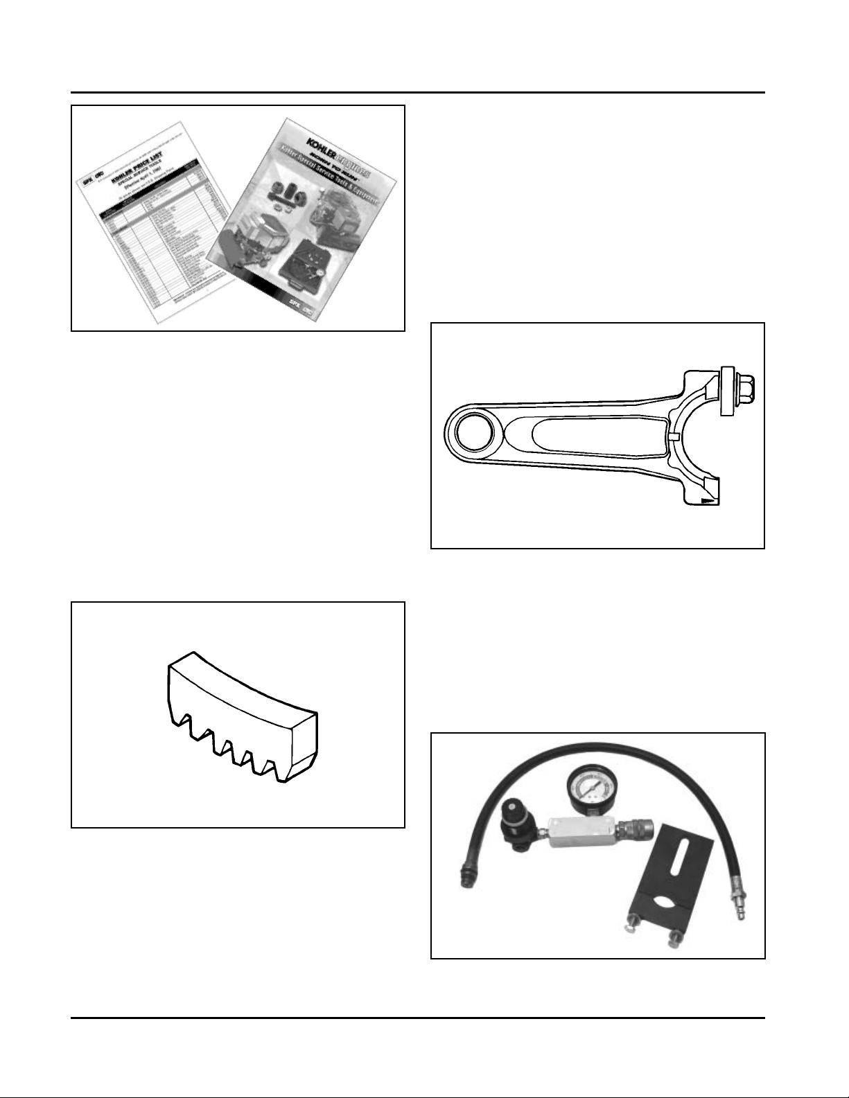
Special Tools
CH18-745
Special Tools
Certain quality tools are designed to help you perform specific disassembly , rep air, and reassembly procedures.
By using tools designed for the job, you can service engines easier, faster, and safer! In addition, you’ll increase
your service capabilities and customer satisfaction by decreasing engine downtime.
Kohler special tools are handled by SPX Corp., a division of Owatonna Tool Corp. (OTC). The tools are easy to
purchase by contacting SPX/OTC by phone, fax, or mail.
Phone: 1-800-533-0492
International: 1-507-455-7223
8:00 am – 8:00 pm EST
Some special tools for this engine are:
Camshaft Endplay Plate........................................................................................ KO1031
Flywheel Strap W rench ......................................................................................... NU10357
Flywheel Puller Kit................................................................................................. NU3226
Rocker Arm Spanner Wrench................................................................................ OEM6200
V alve Guide Reamer ............................................................................................. KO1026
Water Manometer ................................................................................................. KO1048
Cylinder Leakdown Tester ..................................................................................... KO3219
Ignition System Tester ........................................................................................... KO1046
Hydraulic Lifter Removal/Reinstallation Tool.......................................................... KO1044
St arter Service Kit ................................................................................................. KO3226
St arter Retaining Ring Tool.................................................................................... 25 761 18-S
V acuum Gauge ..................................................................................................... KO3223
Tachometer (Digital Inductive) ............................................................................... KO3216
Sp ark Advance Module (SAM) Tester ..................................................................... KO3222
Rectifier-Regulator T ester ....................................................................................... KO3221
Fax: 1-800-578-7375
1-586-578-7375
International: 1-507-455-7063
Mail: SPX Corp., OTC
28635 Mound Rd.
Warren, MI 48092-3499
2
Electronic Fuel Injection (EFI) Service T ools
EFI Service Kit ...................................................................................................... KO3217
Gauge Assembly ............................................................................................... KO3217-4
Pliers................................................................................................................. KO3217-5
Circuit Tester ..................................................................................................... KO3217-6
Jumper Plug, Red (for metal cased ECU) ......................................................... KO3217-7
Tee Valve Assembly .......................................................................................... KO3217-8
Jumper Plug, Blue (for plastic cased ECU) ....................................................... KO3217-9
Some of the specialty tools are shown and mentioned at various points in this manual. A complete catalog of
available tools may be ordered under Kohler Part No. TP-2546. The tool price list is available under Kohler Part No.
TP-2547.
2.1
Section 2
Special Tools
Figure 2-1. Tool Catalog and Price List.
Special Tools You Can Make
Flywheel Holding T ool
Flywheel removal and reinstallation becomes a “snap”
using a handy holding tool which can be made out of an
old “junk” flywheel ring gear as shown in Figure 2-2.
Using an abrasive cut-off wheel, cut out a six tooth
segment of the ring gear as shown. Grind off any burrs
or sharp edges. The segment can be used in place of a
strap wrench. Invert the segment and place it between
the ignition bosses on the crankcase so that the tool
teeth engage the flywheel ring gear teeth. The bosses
will “lock” the tool and flywheel in position for loosening,
tightening or removing with a puller.
Find a used connecting rod from a 10 HP or larger
engine. Remove and discard the rod cap. If it is a PosiLock rod, you will also need to remove the studs. If it is
a Command rod, you will need to grind off the aligning
steps, so the joint surface is flat. Find a 1 in. long
capscrew with the correct thread size to match the
threads in the connecting rod. Obtain a flat washer
with the correct I.D. to slip on the capscrew and an
O.D. of approximately 1 in. Kohler Part No. 12 468 05-S
can be used if you don’t have the right size on hand.
Assemble the capscrew and washer to the joint
surface of the rod, as shown in Figure 2-3.
Figure 2-3. Rocker Arm/Crankshaf t Tool.
Cylinder Leakdown Tester
A Cylinder Leakdown Tester (SPX Part No. KO3219
formerly Kohler 25 761 05-S) is a valuable alternate to a
compression test on these engines. See Figure 2-4. By
pressurizing the combustion chamber from an external
air source, this tool can determine if valves or rings are
leaking. Instructions for using this tester are found in
Section 3 of this manual.
Figure 2-2. Flywheel Holding Tool.
Rocker Arm/Crankshaft Tool
If you don’t have a spanner wrench to lift the rocker
arms or turn the crankshaft, you can make a tool for
doing this out of an old junk connecting rod.
2.2
Figure 2-4. Cylinder Leakdown Tester.
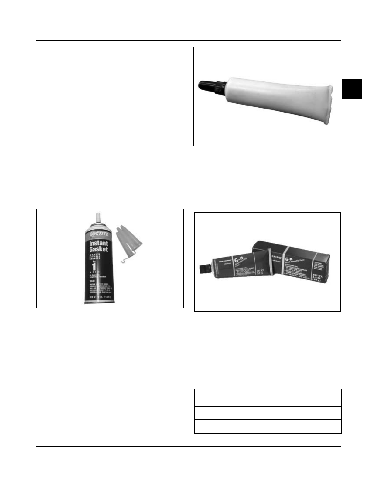
RTV Silicone Sealant
RTV silicone sealant is used as a gasket between the
crankcase and closure plate.
Only oxime-based, oil resistant RTV sealants, such as
those listed below, are approved for use. Loctite® Nos.
5900 and 5910 are recommended for best sealing
characteristics.
Loctite® Ultra Blue 587
Loctite® Ultra Copper
Loctite® Ultra Black 598
Loctite® 5900 (Heavy Body)
Loctite® 5910
Section 2
Special Tools
2
Figure 2-6. Camshaft Break-in Lubricant.
NOTE: Always use fresh sealant. Using outdated
sealant can result in leakage.
Loctite® 5900 is available in a 4 oz aerosol dispenser
with replacement tips under Kohler Part No.
25 597 07-S. See Figure 2-5.
Figure 2-5. Loctite® 5900 Aerosol Dispenser .
Camshaft Break-in Lubricant
Camshaft lubricant, Kohler Part No. 25 357 14-S
(V alspar ZZ613), should be used whenever a new
camshaft and lifters are installed for proper break-in
upon initial startup. Lubricant is included with each
replacement camshaft and lifter , or may also be
obtained separately in a 1/8 oz handy dispensing tube
by the part number listed. See Figure 2-6.
Spline Drive Lubricant
Special spline drive crankshaft lubricant Kohler Part No.
25 357 12-S is available in a 2.8 oz tube for use on all
spline drive applications. This lubricant provides proper
protection against wear-related damage. See Figure
2-7.
Figure 2-7. Crankshaft Spline Drive Lubricant.
Dielectric Grease
Dielectric grease is applied to the outside of the
terminal connections on the SMART -SP ARK™ ignition
modules to prevent formation of a moisture path and
arcing between the terminals. The chart below lists the
approved dielectric greases.
Dielectric Grease
Kohler
Part No.
Vendor
Vendor No./
Description
G.E./Novaguard
Fel-Pro
G661
Lubri-Sel
25 357 11-S
---
2.3

Section 2
Special Tools
2.4
Section 3
Troubleshooting
Troubleshooting Guide
When troubles occur, be sure to check the simple
causes which, at first, may seem too obvious to be
considered. For example, a starting problem could be
caused by an empty fuel tank.
Some general common causes of engine troubles are
listed below. Use these to locate the causing factors.
Refer to the specific section(s) within this service
manual for more detailed information.
Engine Cranks But Will Not Start
1. Empty fuel tank.
2. Fuel shut-off valve closed.
3. Poor fuel, dirt or water in the fuel system.
4. Clogged fuel line.
5. Sp ark plug lead(s) disconnected.
6. Key switch or kill switch in “off” position.
7. Faulty spark plugs.
8. Faulty ignition module(s).
9. SMART-SP ARK™ malfunction (applicable models).
10. Carburetor solenoid malfunction.
1 1. Diode in wiring harness failed in open circuit mode.
12. V acuum fuel pump malfunction, or oil in vacuum
hose.
13. Vacuum hose to fuel pump leaking/cracked.
14. Battery connected backwards.
Engine Start s But Does Not Keep Running
1. Restricted fuel tank cap vent.
2. Poor fuel, dirt or water in the fuel system.
3. Faulty or misadjusted choke or throttle controls.
4. Loose wires or connections that short the kill
terminal of ignition module to ground.
5. Faulty cylinder head gasket.
6. Faulty carburetor.
7. V acuum fuel pump malfunction, or oil in vacuum
hose.
8. Leaking/cracked vacuum hose to fuel pump.
9. Intake system leak.
10. Diode in wiring harness failed in open circuit mode.
Section 3
Troubleshooting
Engine Starts Hard
1. PTO drive is engaged.
2. Dirt or water in the fuel system.
3. Clogged fuel line.
4. Loose or faulty wires or connections.
5. Faulty or misadjusted choke or throttle controls.
6. Faulty spark plugs.
7. Low compression.
8. Weak spark.
9. Fuel pump malfunction causing lack of fuel.
10. Engine overheated-cooling/air circulation
restricted.
1 1. Quality of fuel.
12. Flywheel key sheared.
13. Intake system leak.
Engine Will Not Crank
1. PTO drive is engaged.
2. Battery is discharged.
3. Safety interlock switch is engaged.
4. Loose or faulty wires or connections.
5. Faulty key switch or ignition switch.
6. Faulty electric starter or solenoid.
7. Seized internal engine components.
Engine Runs But Misses
1. Dirt or water in the fuel system.
2. Sp ark plug lead disconnected.
3. Poor quality of fuel.
4. Faulty spark plug(s).
5. Loose wires or connections that intermittently
ground the ignition kill circuit.
6. Engine overheated.
7. Faulty ignition module or incorrect air gap.
8. Carburetor adjusted incorrectly .
9. SMART-SPARK™ malfunction (applicable models).
CH18-745
3
3.1

Section 3
Troubleshooting
Engine Will Not Idle
1. Dirt or water in the fuel system.
2. St ale fuel and/or gum in carburetor.
3. Faulty spark plugs.
4. Fuel supply inadequate.
5. Idle speed adjusting screw improperly set.
6. Idle fuel adjusting needle improperly set (some
models).
7. Low compression.
8. Restricted fuel tank cap vent.
9. Engine overheated-cooling system/air circulation
problem.
Engine Overheats
1. Air intake/grass screen, cooling fins, or cooling
shrouds clogged.
2. Excessive engine load.
3. Low crankcase oil level.
4. High crankcase oil level.
5. Faulty carburetor.
6. Lean fuel mixture.
7. SMART-SPARK™ malfunction (applicable models).
Engine Knocks
1. Excessive engine load.
2. Low crankcase oil level.
3. Old or improper fuel.
4. Internal wear or damage.
5. Hydraulic lifter malfunction.
6. Quality of fuel.
7. Incorrect grade of oil.
Engine Loses Power
1. Low crankcase oil level.
2. High crankcase oil level.
3. Dirty air cleaner element.
4. Dirt or water in the fuel system.
5. Excessive engine load.
6. Engine overheated.
7. Faulty spark plugs.
8. Low compression.
9. Exhaust restriction.
10. SMART-SPARK™ malfunction (applicable models).
1 1. Low battery .
12. Incorrect governor setting.
Engine Uses Excessive Amount of Oil
1. Incorrect oil viscosity/type.
2. Clogged or improperly assembled breather.
3. Breather reed broken.
4. Worn or broken piston rings.
5. Worn cylinder bore.
6. Worn valve stems/valve guides.
7. Crankcase overfilled.
8. Blown head gasket/overheated.
Oil Leaks from Oil Seals, Gaskets
1. Crankcase breather is clogged or inoperative.
2. Breather reed broken.
3. Loose or improperly torqued fasteners.
4. Piston blowby or leaky valves.
5. Restricted exhaust.
External Engine Inspection
Before cleaning or disassembling the engine, make a
thorough inspection of its external appearance and
condition. This inspection can give clues to what might
be found inside the engine (and the cause) when it is
disassembled.
• Check for buildup of dirt and debris on the
crankcase, cooling fins, grass screen and other
external surfaces. Dirt or debris on these areas
are causes of higher operating temperatures and
overheating.
• Check for obvious fuel and oil leaks, and
damaged components. Excessive oil leakage can
indicate a clogged or improperly-assembled
breather, worn/damaged seals and gaskets, or
loose or improperly-torqued fasteners.
• Check the air cleaner cover and base for damage
or indications of improper fit and seal.
• Check the air cleaner element. Look for holes,
tears, cracked or damaged sealing surfaces, or
other damage that could allow unfiltered air into
the engine. Also note if the element is dirty or
clogged. These could indicate that the engine has
been under serviced.
3.2
• Check the carburetor throat for dirt. Dirt in the
throat is further indication that the air cleaner is
not functioning properly .
• Check the oil level. Note if the oil level is within
the operating range on the dipstick, or if it is low
or overfilled.

Section 3
Troubleshooting
• Check the condition of the oil. Drain the oil into a
container - the oil should flow freely . Check for
metal chips and other foreign particles.
Sludge is a natural by-product of combustion; a
small accumulation is normal. Excessive sludge
formation could indicate overrich carburetion, weak
ignition, overextended oil change interval or wrong
weight or type of oil was used, to name a few.
NOTE: It is good practice to drain oil at a location
away from the workbench. Be sure to
allow ample time for complete drainage.
Cleaning the Engine
After inspecting the external condition of the engine,
clean the engine thoroughly before disassembling it.
Also clean individual components as the engine is
disassembled. Only clean parts can be accurately
inspected and gauged for wear or damage. There are
many commercially available cleaners that will quickly
remove grease, oil, and grime from engine parts.
When such a cleaner is used, follow the
manufacturer’s instructions and safety precautions
carefully.
Make sure all traces of the cleaner are removed
before the engine is reassembled and placed into
operation. Even small amounts of these cleaners can
quickly break down the lubricating properties of engine
oil.
Basic Engine Tests
Crankcase Vacuum Test
A partial vacuum should be present in the crankcase
when the engine is operating at normal temperatures.
Pressure in the crankcase (normally caused by a
clogged or improperly assembled breather) can cause
oil to be forced out at oil seals, gaskets, or other
available spots.
Crankcase vacuum is best measured with either a
water manometer (SPX Part No. KO1048, formerly
Kohler Part No. 25 761 02-S) or a vacuum gauge (SPX
Part No. KO3223, formerly Kohler Part No.
25 761 22-S). Complete instructions are provided in the
kits.
T o test the crankcase vacuum with the manometer:
1. Insert the stopper/hose into the oil fill hole. Leave
the other tube of manometer open to atmosphere.
Make sure the shut off clamp is closed.
2. St art the engine and run at no-load high speed
(3200 to 3750 RPM).
3. Open the clamp and note the water level in the
tube.
The level in the engine side should be a minimum
of 10.2 cm (4 in.) above the level in the open
side.
If the level in the engine side is less than
specified (low/no vacuum), or the level in the
engine side is lower than the level in the open
side (pressure), check for the conditions in the
table on page 3.4.
4. Close the shut off clamp before stopping the
engine.
To test the crankcase vacuum with the Vacuum/
Pressure Gauge Kit (SPX Part No. KO3223):
1. Remove the dipstick or oil fill plug/cap.
2. Install the adapter into the oil fill/dipstick tube
opening, upside down over the end of a small
diameter dipstick tube, or directly into engine if a
tube is not used.
3. Push the barbed fitting on the gauge solidly into
the hole in the adapter.
4. Start the engine and bring it up to operating
speed (3200-3600 RPM).
5. Check the reading on the gauge. If the reading is
to the left of “0” on the gauge, vacuum or negative
pressure is indicated. If the reading is to the right
of “0” on the gauge, positive pressure is present.
Crankcase vacuum should be 4-10 (inches of
water) If the reading is below specification, or if
pressure is present, check the following table for
possible causes and remedies.
3
3.3

Section 3
Troubleshooting
No Crankcase Vacuum/Pressure in Crankcase
Possible Cause
1. Crankcase breather clogged or inoperative.
2. Seals and/or gaskets leaking. Loose or
improperly torqued fasteners.
3. Piston blowby or leaky valves. (Confirm by
inspecting components.)
4. Restricted exhaust.
Compression T est
Some of these engines are equipped with an automatic
compression release (ACR) mechanism. Because of
the ACR mechanism, it is dif ficult to obtain an accurate
compression reading. As an alternative, perform a
cylinder leakdown test.
Cylinder Leakdown T est
A cylinder leakdown test can be a valuable alternative
to a compression test. By pressurizing the combustion
chamber from an external air source you can
determine if the valves or rings are leaking, and how
badly .
SPX Part No. KO3219 (formerly Kohler Part No.
25 761 05-S) is a relatively simple, inexpensive
leakdown tester for small engines. The tester includes a
quick disconnect for attaching the adapter hose, and a
holding tool.
Leakdown T est Instructions
1. Run engine for 3-5 minutes to warm it up.
Solution
1. Disassemble breather, clean p arts thoroughly ,
check sealing surfaces for flatness, reassemble,
and recheck pressure.
2. Replace all worn or damaged seals and
gaskets. Make sure all fasteners are tightened
securely . Use appropriate torque values and
sequences when necessary .
3. Recondition piston, rings, cylinder bore, valves,
and valve guides.
4. Repair/replace restricted muffler/exhaust
system.
onto the crankshaft. Install a 3/8" breaker bar into
the hole/slot of the holding tool, so it is
perpendicular to both the holding tool and
crankshaft PTO. If the flywheel end is more
accessible, use a breaker bar and socket on the
flywheel nut/screw to hold it in position. An
assistant may be needed to hold the breaker bar
during testing. If the engine is mounted in a piece
of equipment, it may be possible to hold it by
clamping or wedging a driven component. Just be
certain that the engine cannot rotate off of TDC in
either direction.
4. Install the adapter into the spark plug hole, but do
not attach it to the tester at this time.
5. Connect an air source of at least 50 psi to the
tester.
6. Turn the regulator knob in the increase
(clockwise) direction until the gauge needle is in
the yellow “set” area at the low end of the scale.
2. Remove spark plug(s) and air filter from engine.
3. Rotate the crankshaft until the piston (of cylinder
being tested) is at top dead center of the
compression stroke. Hold the engine in this
position while testing. The holding tool supplied
with the tester can be used if the PTO end of the
crankshaft is accessible. Lock the holding tool
3.4
7. Connect the tester quick-disconnect to the adapter
hose while firmly holding the engine at TDC. Note
the gauge reading and listen for escaping air at
the carburetor intake, exhaust outlet, and
crankcase breather.
8. Check your test results against the following table:

Section 3
Troubleshooting
Leakdown Test Results
Air escaping from crankcase breather ...................................................Defective rings or worn cylinder .
Air escaping from exhaust system......................................................... Defective exhaust valve.
Air escaping from carburetor .................................................................Defective intake valve.
Gauge reading in “low” (green) zone .....................................................Piston rings and cylinder in good condition.
Gauge reading in “moderate” (yellow) zone ...........................................Engine is still usable, but there is some
wear present. Customer should start
planning for overhaul or replacement.
Gauge reading in “high” (red) zone........................................................Rings and/or cylinder have considerable
wear. Engine should be reconditioned or
replaced.
3
3.5

Section 3
Troubleshooting
3.6
Air Cleaner and Air Intake System
Air Cleaners
Air Cleaner and Air Intake System
Section 4
Section 4
CH18-745
General
Most engines are equipped with a replaceable, highdensity paper air cleaner element, surrounded by an
oiled foam precleaner, and housed under a flat outer
cover. This is typically referred to as the standard air
cleaner assembly . See Figures 4-1 and 4-4. Some
engines utilize a heavy-duty style air cleaner as shown
in Figure 4-12.
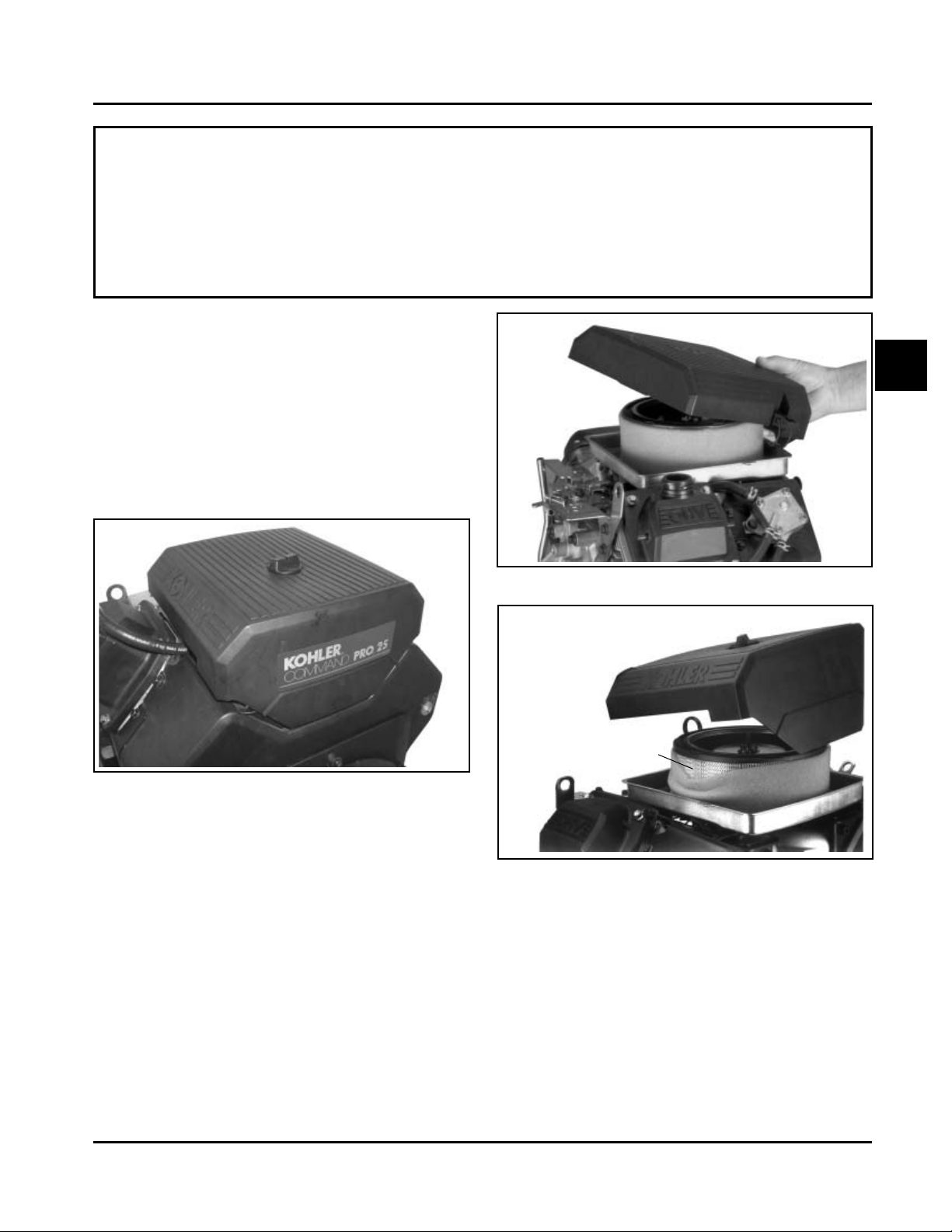
Figure 4-1. Standard Air Cleaner.
4
Figure 4-2. Removing Latch Style Cover.
Cover
Air Cleaner Element
Precleaner
Standard Air Cleaner
Service
Check the air cleaner daily or before starting the
engine. Check for and correct any buildup of dirt and
debris, along with loose or damaged components.
NOTE: Operating the engine with loose or damaged
air cleaner components could allow unfiltered
air into the engine, causing premature wear
and failure.
Figure 4-3. Removing Knob Style Cover .
Precleaner Service
If so equipped, wash and reoil the precleaner every 25
hours of operation (more often under extremely dusty
or dirty conditions).
To service the precleaner, perform the following steps:
1. Unhook the latches or loosen the retaining knob,
and remove the cover.
2. Remove the foam precleaner from the paper air
cleaner element.
4.1
Section 4
Air Cleaner and Air Intake System
3. Wash the precleaner in warm water with
detergent. Rinse the precleaner thoroughly until
all traces of detergent are eliminated. Squeeze
out excess water (do not wring). Allow the
precleaner to air dry .
4. Saturate the precleaner with new engine oil.
Squeeze out all excess oil.
5. Reinstall the precleaner over the paper air cleaner
element.
6. Reinstall the air cleaner cover . Secure the cover
with the two latches or the retaining knob.
Element Cover
Element
Figure 4-4. Air Cleaner Components.
Wing Nut
Precleaner
Seal
Figure 4-6. Removing Elements.
Figure 4-7. Removing Rubber Seal from Bracket.
Paper Element Service (Standard Type)
Every 100 hours of operation (more often under
extremely dusty or dirty conditions), replace the paper
element. Follow these steps:
Figure 4-5. Removing Element Cover Wing Nut.
4.2
1. Unhook the latches or loosen the retaining knob,
and remove the cover.
2. Remove the wing nut, element cover, and p aper
element with precleaner (if so equipped).
3. Remove the precleaner (if so equipped) from the
paper element. Service the precleaner as
described in "Precleaner Service".
4. Do not wash the paper element or use
pressurized air, as this will damage the element.
Replace a dirty , bent, or damaged element with a
genuine Kohler element. Handle new elements
carefully; do not use if the sealing surfaces are
bent or damaged.
Section 4
Air Cleaner and Air Intake System
5. Check the seal for any damage or deterioration.
Replace as necessary . See Figure 4-7.
6. Reinstall the seal, paper element, precleaner ,
element cover, and wing nut.
7. Reinstall the air cleaner cover and secure with the
latches or the retaining knob.
NOTE: Make sure the correct depth air cleaner
element and rubber seal are used for the
engine spec involved. Some engines use
a deeper or extra capacity air cleaner
and a longer rubber seal.
4
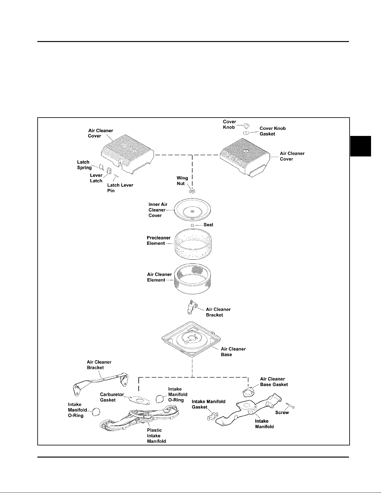
Figure 4-8. Exploded View of St andard Air Int ake System Component s.
4.3
 Loading...