


SERVICE MANUAL
 COMMAND PRO
CH940-CH980
HORIZONTAL CRANKSHAFT

Contents
1
Section 1. Safety and General Information ............................................................................
2
Section 2. Tools & Aids ............................................................................................................
3
Section 3. Troubleshooting .....................................................................................................
4
Section 4. Air Cleaner and Air Intake System ........................................................................
5
Section 5. Fuel System and Governor ....................................................................................
6
Section 6. Lubrication System ................................................................................................
7
Section 7. Electrical System and Components ......................................................................
8
Section 8. Disassembly ............................................................................................................
9
Section 9. Inspection and Reconditioning .............................................................................
10
Section 10. Reassembly ..........................................................................................................

Section 1
Safety and General Information
Section 1 |
1 |
Safety and General Information
Safety Precautions
To ensure safe operation please read the following statements and understand their meaning. Also refer to your equipment manufacturer's manual for other important safety information. This manual contains safety precautions which are explained below. Please read carefully.
WARNING
Warning is used to indicate the presence of a hazard that can cause severe personal injury, death, or substantial property damage if the warning is ignored.
CAUTION
Caution is used to indicate the presence of a hazard that will or can cause minor personal injury or property damage if the caution is ignored.
NOTE
Note is used to notify people of installation, operation, or maintenance information that is important but not hazard-related.
For Your Safety!
These precautions should be followed at all times. Failure to follow these precautions could result in injury to yourself andothers.
 WARNING
Accidental Starts can cause severe injury or death.
Disconnect and ground spark plug leads before servicing.
Accidental Starts!
Disabling engine. Accidental starting can cause severe injury or death.
Before working on the engine or equipment, disable the engine as follows:
1)Disconnect the spark plug lead(s).
2)Disconnect negative (-) battery cable frombattery.
 WARNING
Rotating Parts can cause severe injury.
Stay away while engine is in operation.
Rotating Parts!
Keep hands, feet, hair, and clothing away fromallmovingpartstopreventinjury. Never operate the engine with covers, shrouds,orguardsremoved.
 WARNING
Hot Parts can cause severe burns.
Do not touch engine while operating or just after stopping.
Hot Parts!
Enginecomponentscangetextremely hot from operation. To prevent severe burns, do not touch these areas while the engineisrunning-orimmediatelyafterit is turned off. Never operate the engine with heat shields or guards removed.
1.1

Section 1
Safety and General Information
 WARNING
Explosive Fuel can cause fires and severe burns.
Do not fill the fuel tank while the engine is hot or running.
Explosive Fuel!
Gasoline is extremely flammable and its vapors can explode if ignited. Store gasoline only in approved containers, in wellventilated,unoccupiedbuildings, away from sparks or flames. Do not fill the fuel tank while the engine is hot or running, since spilled fuel could ignite if it comes in contact with hot parts or sparksfromignition.Donotstartthe engine near spilled fuel. Never use gasoline as a cleaning agent.
 WARNING
Cleaning Solvents can cause severe injury or death.
Use only in well ventilated areas away from ignition sources.
Flammable Solvents!
Carburetorcleanersandsolventsare extremelyflammable.Keepsparks, flames, and other sources of ignition away from the area. Follow the cleaner manufacturer’swarningsand instructionsonitsproperandsafeuse. Never use gasoline as a cleaning agent.
 WARNING
Carbon Monoxide can cause severe nausea, fainting or death.
Avoid inhaling exhaust fumes, and never run the engine in a closed building or confined area.
Lethal Exhaust Gases!
Engine exhaust gases contain poisonous carbonmonoxide.Carbonmonoxideis odorless, colorless, and can cause death if inhaled. Avoid inhaling exhaust fumes, and never run the engine in a closed buildingorconfinedarea.
 WARNING
Explosive Gas can cause fires and severe acid burns.
Charge battery only in a well ventilated area. Keep sources of ignition away.
Explosive Gas!
Batteries produce explosive hydrogen gas while being charged. To prevent a fire or explosion, charge batteries only in well ventilated areas. Keep sparks, open flames, and other sources of ignition away from the battery at all times. Keep batteries out of the reach of children. Remove all jewelry when servicing batteries.
Before disconnecting the negative (-) ground cable, make sure all switches are OFF. If ON, a spark will occur at the ground cable terminal which could cause an explosion if hydrogen gas or gasoline vaporsarepresent.
 CAUTION
Electrical Shock can cause injury.
Do not touch wires while engine is running.
Electrical Shock!
Nevertouchelectricalwiresor components whilethe engine is running. They can be sources of electrical shock.
1.2

Section 1
Safety and General Information
Engine Identification Numbers
When ordering parts, or in any communication
involving an engine, always give the Model, 1
Specification, and Serial Numbers, including letter suffixes if there are any.
The engine identification numbers appear on a decal, or decals, affixed to the engine shrouding. See Figure 1-1. An explanation of these numbers is shown in
Figure 1-2. Identification
Decal
Figure 1-1. Engine Identification Decal Location.
A. Model No.
Command Engine
Horizontal Crankshaft
Numerical Designation
B. Spec. No.
C H 980 S
CH940-0001
CH960-0001
CH980-0001
Complete Spec. Number (Incorporating Model No. with Variation No. of Basic Spec.)
Version Code
S = Electric Start
C. Serial No. |
|
3705810334 |
|
|
|
||||
Year Manufactured Code |
|
|
|
|
|
|
|
|
Factory Code |
|
|
|
|
|
|||||
|
|
|
|
|
|
|
|||
Code Year
372007
382008
Figure 1-2. Explanation of Engine Identification Numbers.
1.3
Section 1
Safety and General Information
Oil Recommendations
Using the proper type and weight of oil in the crankcase is extremely important. So is checking oil daily and changing oil regularly. It is also recommended that a consistent brand of oil be used. Failure to use the correct oil, or using dirty oil, causes premature engine wear and failure.
Oil Type
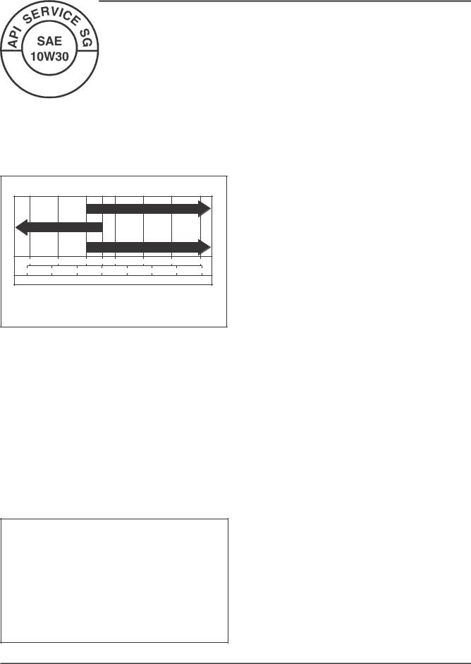
Use high-quality detergent oil of API (American
Petroleum Institute) Service Class SG, SH, SJ or higher. Select the viscosity based on the air temperature at the time of operation as shown in the following table.
RECOMMENDED SAE VISCOSITY GRADES
|
** |
|
|
* |
|
10W-30 |
|
|
|
|
5W-20, 5W-30 |
|
|
|
|
|
|||
|
|
|
|
|
|
|
|
||
|
|
|
|
|
|
Kohler 10W-30 |
|
|
|
°F |
-20 |
0 |
20 |
32 |
40 |
|
60 |
80 |
100 |
°C -30 |
-20 |
-10 |
0 |
|
10 |
20 |
30 |
40 |
|
TEMPERATURE RANGE EXPECTED BEFORE NEXT OIL CHANGE
* Use of synthetic oil having 5W-20 or 5W-30 rating is acceptable, up to 4°C (40°F)
**Synthetic oils will provide better starting in extreme cold below 23°C (-10°F)
NOTE: Using other than service class SG, SH, SJ or higher oil or extending oil change intervals longer than recommended can cause engine damage.
NOTE: Synthetic oils meeting the listed classifications may be used with oil changes performed at the recommended intervals. However, to allow piston rings to properly seat, a new or rebuilt engine should be operated for at least 50 hours using standard petroleum based oil before switching to synthetic oil.
A logo or symbol on oil containers identifies the API service class and SAE viscosity grade. See Figure 1-3.
Figure 1-3. Oil Container Logo.
Refer to Section 6 - Lubrication System for detailed procedures on checking the oil, changing the oil and changing the oil filter.
Fuel Recommendations
WARNING: Explosive Fuel!
Gasoline is extremely flammable and its vapors can explode if ignited. Before servicing the fuel system, make sure there are no sparks, open flames or other sources of ignition nearby as these can ignite gasoline vapors. Disconnect and ground the spark plug leads to prevent the possibility of sparks from the ignition system.
General Recommendations
Purchase gasoline in small quantities that can be used within 30 days, and store only in clean, approved containers. Do not use gasoline left over from the previous season, unless treated with a fuel stabilizer (see Storage), to minimize gum deposits and ensure easy starting. Do not use gasoline containing Methanol, or add oil to the gasoline.
Do not overfill the fuel tank. Leave room for the fuel to expand.
Fuel Type
For best results, use only clean, fresh, unleaded gasoline with a pump sticker octane rating of 87 or higher. In countries using the Research method, it should be 90 octane minimum.
Unleaded gasoline is recommended as it leaves less combustion chamber deposits and reduces harmful exhaust emissions. Leaded gasoline is not recommended and must not be used on EFI engines, or on other models where exhaust emissions are regulated.
Gasoline/Alcohol Blends
Gasohol (up to 10% ethyl alcohol, 90% unleaded gasoline by volume) is approved as a fuel for Kohler engines. Other gasoline/alcohol blends including E20 and E85 are not to be used and not approved. Any failures resulting from use of these fuels will not be warranted.
Gasoline/Ether Blends
Methyl Tertiary Butyl Ether (MTBE) and unleaded gasoline blends (up to a maximum of 15% MTBE by volume) are approved as a fuel for Kohler engines. Other gasoline/ether blends are not approved.
1.4

Section 1
Safety and General Information
Periodic Maintenance Instructions
WARNING: Accidental Starts! |
1 |
|
|
Disabling engine. Accidental starting can cause severe injury or death.Before working on the engine or equipment, disable |
|
the engine as follows: 1) Disconnect the spark plug lead(s). 2) Disconnect negative (-) battery cable from battery. |
|
Maintenance Schedule |
|
These required maintenance procedures should be performed at the frequency stated in the table. They should |
|
also be included as part of any seasonal tune-up. |
|
Frequency |
Maintenance |
Refer to: |
|
|
|
|
|
|
• Fill fuel tank. |
Section 5 |
|
Daily or Before |
• Check oil level. |
Section 6 |
|
Starting Engine |
• Check air cleaner for dirty1, loose, or damaged parts. |
Section 4 |
|
|
• Check air intake and cooling areas, clean as necessary. |
Section 4 |
|
|
|
|
|
Weekly |
• Check filter minder or air cleaner element. |
Section 4 |
|
|
|
|
|
|
• Check air cleaner element. |
Section 4 |
|
Seasonally or |
• Replace fuel filter. |
Section 5 |
|
• Change oil. Oil filter is recommended. |
|
||
Every 150 Hours |
|
||
(More frequently under severe conditions.) |
Section 6 |
||
|
|||
|
• Remove cooling shrouds and clean cooling areas1. |
Section 4 |
|
|
• Check oil cooler fins, clean as necessary. |
Section 6 |
|
|
|
|
|
Every 200 Hours |
• Check spark plug condition and gap. |
Section 7 |
|
|
|
|
|
Seasonally or |
• Change oil filter. |
Section 6 |
|
Every 300 Hours |
• Replace air cleaner element. |
Section 4 |
|
Yearly or |
• Have solenoid shift starter disassembled and cleaned2. |
Section 7 |
|
Every 500 Hours |
• Have crankshaft splines lubricated2. |
|
|
|
|
|
|
Every 600 Hours |
• Replace inner air cleaner element. |
Section 4 |
|
• Replace spark plugs. |
Section 7 |
||
|
¹Performthesemaintenanceproceduresmorefrequentlyunderextremelydusty,dirtyconditions. 2Have a Kohler Engine Service Dealer perform this service.
Storage
If the engine will be out of service for 30 days or more, use the following storage procedure.
1.Clean the exterior surfaces of the engine. Avoid spraying water at the wiring harness or any of the electrical components.
2.Change the oil and oil filter while the engine is still warm from operation. See Changing Oil and Oil Filter in Section 6.
3.The fuel system must be completely emptied, or the gasoline must be treated with a stabilizer to prevent deterioration. If you choose to use a stabilizer, follow the manufacturer’s recommendations, and add the correct amount for the capacity of the fuel system.
Fill the fuel tank with clean, fresh gasoline. Run the engine for 2 to 3 minutes to get stabilized fuel into the rest of the system. Close the fuel shut-off valve when the unit is being stored or transported.
To empty the system, run the engine until the tank and the system are empty.
4.Remove the spark plugs and add one tablespoon of engine oil into each spark plug hole. Install the spark plugs, but do not connect the plug leads.
Crank the engine two or three revolutions.
5.Disconnect the battery or use a battery minder to keep the battery charged during storage.
6.Store the engine in a clean, dry place.
1.5

Section 1
Safety and General Information
Dimensions in millimeters.
Inch equivalents shown in [ ].
Figure 1-4. Typical CH PRO Series Engine Dimensions with Heavy-Duty Air Cleaner.
1.6

Section 1
Safety and General Information
General Specifications¹ |
|
|
|
Power (@ 3600 RPM, exceeds Society of Automotive Engineers-Small Engine Test Code J1940.) |
|
||
1 |
|||
CH940 ........................................................................................................ |
25.4 kW (34 HP) |
||
CH960 ........................................................................................................ |
26.9 kW (36 HP) |
||
CH980 |
28.3 kW (38 HP) |
|
|
|
|||
Bore ................................................................................................................... |
90 mm (3.54 in.) |
|
|
Stroke ................................................................................................................ |
78.5 mm (3.1 in.) |
|
|
Displacement ................................................................................................... |
999 cc (61 cu. in.) |
|
|
Compression Ratio ......................................................................................... |
8.8:1 |
|
|
Dry Weight ...................................................................................................... |
59.8 kg (132 lb.) |
|
|
Oil Capacity (w/filter) - approximate, |
|
|
|
determined by oil filter used ........................................................................ |
2.7 L (2.9 U.S. qt.) |
|
|
Angle of Operation - Maximum (At Full Oil Level) All Directions ......... |
25° |
|
|
Blower Housing and Sheet Metal |
|
|
|
M6 Shoulder Screw Torque |
|
|
|
New, Untapped Hole (casting) .............................................................. |
10.7 N·m (95 in. lb.) |
|
|
Used, Tapped Hole (casting) ................................................................... |
7.3 N·m (65 in. lb.) |
|
|
New, Extruded Hole (sheet metal) ........................................................ |
4.0 N·m (35 in. lb.) |
|
|
Used, Extruded Hole (sheet metal) ........................................................ |
2.0 N·m (17.7 in. lb.) |
|
|
Mounting Clip (valley baffle) ................................................................. |
2.5 N·m (22.1 in. lb.) |
|
|
M6 Screw Torque |
|
|
|
New, Untapped Hole (casting) .............................................................. |
10.7 N·m (95 in. lb) |
|
|
Used, Tapped Hole (casting) ................................................................... |
7.3 N·m (65 in. lb) |
|
|
Rectifier-Regulator Fastener Torque ........................................................... |
2.0 N·m (18 in. lb.) |
|
|
Oil Cooler Fastener Torque ............................................................................ |
2.2 N·m (20 in. lb.) |
|
|
Camshaft |
|
|
|
End Play ........................................................................................................... |
0.3/1.3 mm (0.011/0.051 in.) |
|
|
Running Clearance ......................................................................................... |
0.025/0.063 mm (0.0010/0.0025 in.) |
|
|
Bore I.D. |
|
|
|
New ........................................................................................................... |
20.000/20.025 mm (0.7874/0.7884 in.) |
|
|
Max. Wear Limit ...................................................................................... |
20.038 mm (0.7889 in.) |
|
|
Camshaft Bearing Surface O.D. |
|
|
|
New ........................................................................................................... |
19.962/19.975 mm (0.7859/0.7864 in.) |
|
|
Max. Wear Limit ...................................................................................... |
19.959 mm (0.7858 in.) |
|
|
Cam Lobe Profile (Minimum Dimension, Measured From Base Circle To Top Of Lobe) |
|
||
Exhaust ............................................................................................................. |
35 mm (1.3779 in.) |
|
|
Intake ................................................................................................................ |
35 mm (1.3779 in.) |
|
|
¹Values are in Metric units. Values in parentheses are English equivalents. Lubricate threads with engine oil prior to assembly.
1.7

Section 1
Safety and General Information
Carburetor, Intake Manifold, and Air Cleaner |
|
Intake Manifold Mounting Fastener Torque |
|
Torque (Using Sequence) in Two Stages ............................................... |
first to 16.9 N·m (150 in. lb.) |
|
finally to 22.6 N·m (200 in. lb.) |
Carburetor/Air Cleaner Mounting Nut Torque ......................................... |
7.9 N·m (70 in. lb.) |
Air Cleaner Mounting Screw Torque (Into Intake Manifold) ................... |
9.9 N·m (88 in. lb.) |
Control Bracket |
|
Mounting Screw (Into Intake Manifold from Air Cleaner) Torque ......... |
9.9 N·m (88 in. lb.) |
Connecting Rod |
|
Cap Fastener Torque (Torque In Increments) ............................................. |
11.3 N·m (100 in. lb.) |
Crankpin End I.D. @ 70°F |
|
New ........................................................................................................... |
44.030/44.037 mm (1.7334/1.7337 in.) |
Max. Wear Limit ...................................................................................... |
0.070 mm (0.0028 in.) |
Connecting Rod-to-Crankpin Running Clearance |
|
New ........................................................................................................... |
0.030/0.055 mm (0.0012/0.0022 in.) |
Max. Wear Limit ...................................................................................... |
0.070 mm (0.0028 in.) |
Connecting Rod-to-Crankpin Side Clearance ............................................ |
0.30/0.59 mm (0.0118/0.0232 in.) |
Connecting Rod-to-Piston Pin Running Clearance ................................... |
0.015/0.028 mm (0.0006/0.0011 in.) |
Piston Pin End I.D. @ 70°F |
|
New ........................................................................................................... |
19.023/19.015 mm (0.7489/0.7486 in.) |
Max. Wear Limit ...................................................................................... |
19.036 mm (0.7494 in.) |
Crankcase |
|
Governor Cross Shaft Bore I.D. |
|
New ........................................................................................................... |
8.025/8.050 mm (0.3159/0.3169 in.) |
Max. Wear Limit ...................................................................................... |
8.088 mm (0.3184 in.) |
Breather Cover Fastener Torque .................................................................. |
5.7 N·m (51 in. lb.) |
Oil Drain Plug Torque .................................................................................... |
21.4 N·m (15.7 ft. lb.) |
Closure Plate |
|
Closure Plate Fastener Torque ...................................................................... |
24.4 N·m (216 in. lb.) |
Reservoir (Oil) |
|
Mounting Screw Torque ................................................................................ |
24.4 N·m (216 in. lb.) |
Crankshaft |
|
End Play (Free) ................................................................................................ |
0.30/1.50 mm (0.011/0.059 in.) |
Crankshaft Bore (In Crankcase) |
|
New, Without Main Bearing ................................................................. |
50.00/50.025 mm (1.9685/1.969 in.) |
With Main Bearing Installed ................................................................. |
45.040/45.145 mm (1.7732/1.7773 in.) |
Max. Wear Limit ...................................................................................... |
45.158 mm (1.7778 in.) |
Crankshaft to Sleeve Bearing (In Crankcase) |
|
Running Clearance - New ...................................................................... |
0.040/0.167 mm (0.0015/0.0065 in.) |
1.8
|
Section 1 |
|
|
Safety and General Information |
|
Crankshaft Bore (In Closure Plate) - New, Without Bearing |
................... 50.025/50.00 mm (1.9694/1.9685 in.) |
|
Crankshaft to Sleeve Bearing (In Closure Plate) |
|
|
Running Clearance - New ...................................................................... |
0.040/0.167 mm (0.0015/0.0065 in.) |
1 |
Flywheel End Main Bearing Journal |
|
|
O.D. - New ................................................................................................ |
44.978/45.00 mm (1.770/1.771 in.) |
|
O.D. - Max. Wear Limit ........................................................................... |
44.90 mm (1.767 in.) |
|
Max. Taper ................................................................................................ |
0.022 mm (0.0009 in.) |
|
Max. Out-of-Round ................................................................................. |
0.025 mm (0.0010 in.) |
|
Closure Plate End Main Bearing Journal |
|
|
O.D. - New ................................................................................................ |
44.978/45.00 mm (1.770/1.771 in.) |
|
O.D. - Max. Wear Limit ........................................................................... |
44.90 mm (1.767 in.) |
|
Max. Taper ................................................................................................ |
0.022 mm (0.0009 in.) |
|
Max. Out-of-Round ................................................................................. |
0.025 mm (0.0010 in.) |
|
Connecting Rod Journal |
|
|
O.D. - New ................................................................................................ |
43.982/44.000 mm (1.731/1.732 in.) |
|
O.D. - Max. Wear Limit ........................................................................... |
43.97 mm (1.731 in.) |
|
Max. Taper ................................................................................................ |
0.018 mm (0.0007 in.) |
|
Max. Out-of-Round ................................................................................. |
0.025 mm (0.0010 in.) |
|
Width ........................................................................................................ |
53.00/53.09 mm (2.0866/2.0901 in.) |
|
Crankshaft T.I.R. |
|
|
PTO End, Crank in Engine ...................................................................... |
0.279 mm (0.0110 in.) |
|
Entire Crank, in V-Blocks ....................................................................... |
0.10 mm (0.0039 in.) |
|
Cylinder Bore |
|
|
Cylinder Bore I.D. |
|
|
New ........................................................................................................... |
90.000/90.025 mm (3.543/3.544 in.) |
|
Max. Wear Limit ...................................................................................... |
90.075 mm (3.546 in.) |
|
Max. Out-of-Round ................................................................................. |
0.013 mm (0.00051 in.) |
|
Max. Taper ................................................................................................ |
0.013 mm (0.00051 in.) |
|
Main Bearing I.D. (Crankcase/Closure Plate) |
|
|
New (Installed) ........................................................................................ |
45.040/45.145 mm (1.773/1.777 in.) |
|
Max. Wear Limit ...................................................................................... |
45.158 mm |
|
Cylinder Head |
|
|
Cylinder Head Fastener Torque |
|
|
Head Bolt - Torque in Two Stages ......................................................... |
first to 22.6 N·m (200 in. lb.) |
|
|
finally to 45.2 N·m (400 in. lb.) |
|
Max. Out-of-Flatness ...................................................................................... |
0.076 mm (0.003 in.) |
|
Pipe Plug (3/4") Torque ................................................................................... |
28.25 N·m (250 in. lb.) |
|
Rocker Arm Screw Torque ............................................................................ |
14.6 N·m (130 in. lb.) |
|
Fan/Flywheel |
|
|
Fan Fastener Torque ....................................................................................... |
9.9 N·m (88 in. lb.) |
|
Flywheel Retaining Screw Torque ............................................................... |
67.8 N·m (50 ft. lb.) |
|
1.9

Section 1
Safety and General Information
Grass Screen |
|
Hex Stud Torque .............................................................................................. |
9.9 N·m (88 in. lb.) |
Mounting Screw Torque ................................................................................ |
9.9 N·m (88 in. lb.) |
Front Drive Shaft Screw Torque (Into Flywheel) ....................................... |
24.4 N·m (216 in. lb.) |
Governor |
|
Governor Cross Shaft-to-Crankcase Running Clearance ........................ |
0.025/0.087 mm (0.0009/0.0034 in.) |
Governor Cross Shaft O.D. |
|
New ........................................................................................................... |
7.963/8.000 mm (0.3135/0.3149 in.) |
Max. Wear Limit ...................................................................................... |
7.936 mm (0.3124 in.) |
Governor Gear Shaft-to-Governor Gear Running Clearance ................. |
0.070/0.160 mm (0.0027/0.0063 in.) |
Governor Gear Shaft O.D. |
|
New ........................................................................................................... |
5.990/6.000 mm (0.2358/0.2362 in.) |
Max. Wear Limit ...................................................................................... |
5.977 mm (0.2353 in.) |
Governor Lever Nut Torque ......................................................................... |
7.3 N·m (65 in. lb.) |
Ignition |
|
Spark Plug Type (Champion® or Equivalent) ............................................. |
XC10YC |
Spark Plug Gap ............................................................................................... |
0.76 mm (0.030 in.) |
Spark Plug Torque .......................................................................................... |
24.4-29.8 N·m (18-22 ft. lb.) |
Ignition Module Air Gap ............................................................................... |
0.28/0.33 mm (0.011/0.013 in.) |
Ignition Module Fastener Torque ................................................................. |
6.2 N·m (55 in. lb.) into new holes, or |
Lifter Feed Chamber |
4.0 N·m (35 in. lb.) into used holes |
|
|
Cover/Baffle Screw Torque ............................................................................ |
6.2 N·m (55 in. lb.) |
Muffler |
|
Muffler Retaining Nut Torque ...................................................................... |
24.4 N·m (216 in. lb.) |
Oil Cooler |
|
Mounting Screws Torque .............................................................................. |
3.9 N·m (35 in. lb.) |
Oil Filter |
|
Oil Filter Torque .............................................................................................. |
3/4-1 turn after gasket contact |
Oil Filter Adapter/Housing |
|
Mounting Screw Torque ................................................................................ |
24.4 N·m (216 in. lb.) |
Piston, Piston Rings, and Piston Pin |
|
Piston-to-Piston Pin Running Clearance .................................................... |
0.006/0.018 mm (0.0002/0.0007 in.) |
Piston Pin Bore I.D. |
|
New ........................................................................................................... |
19.006/17.013 mm (0.7482/0.7485 in.) |
Max. Wear Limit ...................................................................................... |
19.025 mm (0.7490 in.) |
Piston Pin O.D. |
|
New ........................................................................................................... |
18.995/19.000 mm (0.7478/0.7480 in.) |
Max. Wear Limit ...................................................................................... |
18.994 mm (0.7478 in.) |
1.10

|
Section 1 |
|
|
Safety and General Information |
|
Top Compression Ring-to-Groove Side Clearance .................................... |
0.04/0.08 mm (0.0015/0.0031 in.) |
|
Middle Compression Ring-to-Groove Side Clearance .............................. |
0.04/0.08 mm (0.0015/0.0031 in.) |
|
|
|
1 |
Oil Control Ring-to-Groove Side Clearance ............................................... |
0.03/0.19 mm (0.0011/0.0074 in.) |
|
Top and Center Compression Ring End Gap |
|
|
New Bore .................................................................................................. |
0.30/0.55 mm (0.011/0.021 in.) |
|
Used Bore (Max.) ...................................................................................... |
0.94 mm (0.037 in.) |
|
Piston Thrust Face O.D.² |
|
|
New ........................................................................................................... |
89.953/89.967 mm (3.5414/3.5420 in.) |
|
Max. Wear Limit ...................................................................................... |
89.925 mm (3.540 in.) |
|
Piston Thrust Face-to-Cylinder Bore² Running Clearance |
|
|
New ........................................................................................................... |
0.033/0.72 mm (0.0013/0.0028 in.) |
|
Starter Assembly |
|
|
Thru Bolt Torque |
|
|
Delco-Remy (Solenoid Shift) .................................................................. |
5.6-9.0 N·m (49-79 in. lb.) |
|
Mounting Screw Torque ................................................................................ |
15.3 N·m (135 in. lb.) |
|
Brush Holder Mounting Screw Torque |
|
|
Delco-Remy Starter ................................................................................. |
2.5-3.3 N·m (22-29 in. lb.) |
|
Solenoid (Starter) |
|
|
Mounting Hardware Torque |
|
|
Delco-Remy Starter ................................................................................. |
4.0-6.0 N·m (35-53 in. lb.) |
|
Nut, Positive (+) Brush Lead Torque |
|
|
Delco-Remy Starter ................................................................................. |
8.0-11.0 N·m (71-97 in. lb.) |
|
Stator |
|
|
Mounting Screw Torque ................................................................................ |
6.2 N·m (55 in. lb.) |
|
Throttle/Choke Control Bracket |
|
|
Fastener Torque ............................................................................................... |
9.9 N·m (88 in. lb.) |
|
Valve Cover |
|
|
Valve Cover Fastener Torque ........................................................................ |
7.9 N·m (70 in. lb.) |
|
Valves and Valve Lifters |
|
|
Hydraulic Valve Lifter to Crankcase Running Clearance ........................ |
0.012/0.050 mm (0.0004/0.0019 in.) |
|
Intake Valve Stem-to-Valve Guide Running Clearance ........................... |
0.038/0.076 mm (0.0015/0.0030 in.) |
|
Exhaust Valve Stem-to-Valve Guide Running Clearance ........................ |
0.050/0.088 mm (0.0020/0.0035 in.) |
|
Intake Valve Guide I.D. |
|
|
New ........................................................................................................... |
7.038/7.058 mm (0.2771/0.2779 in.) |
|
Max. Wear Limit ...................................................................................... |
7.135 mm (0.2809 in.) |
|
Exhaust Valve Guide I.D. |
|
|
New ........................................................................................................... |
7.038/7.058 mm (0.2771/0.2779 in.) |
|
Max. Wear Limit ...................................................................................... |
7.159 mm (0.2819 in.) |
|
²Measure 11 mm (0.433 in.) above the bottom of the piston skirt at right angles to the piston pin.
1.11

Section 1
Safety and General Information
Valve Guide Reamer Size |
|
Standard ................................................................................................... |
7.048 mm (0.2775 in.) |
0.25 mm O.S. ............................................................................................. |
7.298 mm (0.2873 in.) |
Nominal Valve Face Angle ............................................................................ |
45° |
General Torque Values
Metric Fastener Torque Recommendations for Standard Applications
Tightening Torque: N·m (in. lb.) + or - 10% |
|
|
|
|
|
|
||||||
|
|
|
|
|
Property Class |
|
|
|
Noncritical |
|||
|
|
|
|
|
|
|
|
|
|
|
Fasteners |
|
|
4.8 |
|
|
|
|
|
|
|
|
Into Aluminum |
||
|
|
|
|
|
|
|
|
|
|
|
||
Size |
|
|
|
|
|
|
|
|
|
|
|
|
M4 |
1.2 |
(11) |
1.7 |
(15) |
2.9 |
(26) |
4.1 |
(36) |
5.0 |
(44) |
2.0 |
(18) |
M5 |
2.5 |
(22) |
3.2 |
(28) |
5.8 |
(51) |
8.1 |
(72) |
9.7 |
(86) |
4.0 |
(35) |
M6 |
4.3 |
(38) |
5.7 |
(50) |
9.9 |
(88) |
14.0 |
(124) |
16.5 |
(146) |
6.8 |
(60) |
M8 |
10.5 |
(93) |
13.6 |
(120) |
24.4 |
(216) |
33.9 |
(300) |
40.7 |
(360) |
17.0 |
(150) |
Tightening Torque: N·m (ft. lb.) + or - 10% |
|
|
|
|
|
||||
|
|
|
Property Class |
|
|
|
Noncritical |
||
|
|
|
|
|
|
|
|
|
Fasteners |
|
|
|
|
|
|
|
|
|
Into Aluminum |
M10 |
21.7 (16) |
27.1 (20) |
47.5 |
(35) |
66.4 |
(49) |
81.4 |
(60) |
33.9 (25) |
M12 |
36.6 (27) |
47.5 (35) |
82.7 |
(61) |
116.6 |
(86) |
139.7 |
(103) |
61.0 (45) |
M14 |
58.3 (43) |
76.4 (55) |
131.5 |
(97) |
184.4 |
(136) |
219.7 |
(162) |
94.9 (70) |
1.12

Section 1
Safety and General Information
English Fastener Torque Recommendations for Standard Applications
Tightening Torque: N·m (in. lb.) + or - 20% |
|
|
|
|
|
1 |
|||
|
|
|
|
|
|
|
|
|
|
Bolts, Screws, Nuts and Fasteners |
|
|
|
|
Grade 2 or 5 |
|
|
||
|
|
|
|
|
|
||||
Assembled Into Cast Iron or Steel |
|
|
|
|
|
||||
|
|
|
|
Fasteners Into |
|
|
|||
|
|
|
|
|
|
|
|
||
|
|
|
|
|
|
|
Aluminum |
|
|
|
Grade 2 |
Grade 5 |
Grade 8 |
|
|
|
|||
|
|
|
|
|
|
|
|
|
|
Size |
|
|
|
|
|
|
|
|
|
8-32 |
2.3 (20) |
2.8 (25) |
--------- |
|
2.3 (20) |
|
|
||
10-24 |
3.6 (32) |
4.5 (40) |
--------- |
|
3.6 (32) |
|
|
||
10-32 |
3.6 (32) |
4.5 (40) |
--------- |
|
--------- |
|
|
||
1/4-20 |
7.9 (70) |
13.0 (115) |
18.7 (165) |
7.9 (70) |
|
|
|||
1/4-28 |
9.6 (85) |
15.8 (140) |
22.6 (200) |
--------- |
|
|
|||
5/16-18 |
17.0 (150) |
28.3 (250) |
39.6 (350) |
17.0 (150) |
|
|
|||
5/16-24 |
18.7 (165) |
30.5 (270) |
--------- |
|
--------- |
|
|
||
3/8-16 |
29.4 (260) |
--------- |
|
--------- |
--------- |
|
|
||
3/8-24 |
33.9 (300) |
--------- |
|
--------- |
--------- |
|
|
||
|
|
|
|
|
|
|
|
|
|
Tightening Torque: N·m (ft. lb.) + or - 20% |
|
|
|
|
|
|
|||
|
|
|
|
|
|
|
|
|
|
Size |
|
|
|
|
|
|
|
|
|
5/16-24 |
--------- |
|
---------- |
40.7 |
(30) |
--------- |
|
|
|
3/8-16 |
--------- |
|
47.5 |
(35) |
67.8 |
(50) |
--------- |
|
|
3/8-24 |
--------- |
|
54.2 |
(40) |
81.4 |
(60) |
--------- |
|
|
7/16-14 |
47.5 |
(35) |
74.6 |
(55) |
108.5 (80) |
--------- |
|
|
|
7/16-20 |
61.0 |
(45) |
101.7 |
(75) |
142.4 |
(105) |
--------- |
|
|
1/2-13 |
67.8 |
(50) |
108.5 |
(80) |
155.9 |
(115) |
--------- |
|
|
1/2-20 |
94.9 |
(70) |
142.4 |
(105) |
223.7 |
(165) |
--------- |
|
|
9/16-12 |
101.7 |
(75) |
169.5 |
(125) |
237.3 |
(175) |
--------- |
|
|
9/16-18 |
135.6 |
(100) |
223.7 |
(165) |
311.9 |
(230) |
--------- |
|
|
5/8-11 |
149.2 |
(110) |
244.1 |
(180) |
352.6 |
(260) |
--------- |
|
|
5/8-18 |
189.8 |
(140) |
311.9 |
(230) |
447.5 |
(330) |
--------- |
|
|
3/4-10 |
199.3 |
(150) |
332.2 |
(245) |
474.6 |
(350) |
--------- |
|
|
3/4-16 |
271.2 |
(200) |
440.7 |
(325) |
637.3 |
(470) |
--------- |
|
|
|
|
|
|
|
|
|
|
|
|
Torque
Conversions
N·m = in. lb. x 0.113 N·m = ft. lb. x 1.356 in. lb. = N·m x 8.85 ft. lb. = N·m x 0.737
1.13

Section 2
Tools & Aids
Section 2
Tools & Aids
2
Certain quality tools are designed to help you perform specific disassembly, repair, and reassembly procedures. By using tools designed for the job, you can properly service engines easier, faster, and safer! In addition, you’ll increase your service capabilities and customer satisfaction by decreasing engine downtime.
Here is the list of tools and their source.
Separate Tool Suppliers: |
|
|
Kohler Tools |
SE Tools |
Design Technology Inc. |
Contact your source |
415 Howard St. |
768 Burr Oak Drive |
of supply. |
Lapeer, MI 48446 |
Westmont, IL 60559 |
|
Phone 810-664-2981 |
Phone 630-920-1300 |
|
Toll Free 800-664-2981 |
|
|
Fax 810-664-8181 |
|
Tools
Description |
Source/Part No. |
|
|
|
|
Balance Gear Timing Tool (K & M Series) |
Kohler 25 455 06-S |
|
To hold balance gears in timed position when assembling engine. |
(Formerly Y-357) |
|
|
|
|
Camshaft Endplay Plate |
SE Tools KLR-82405 |
|
For checking camshaft endplay. |
||
|
||
|
|
|
Camshaft Seal Protector (Aegis) |
SE Tools KLR-82417 |
|
To protect seal during camshaft installation. |
||
|
||
|
|
|
Cylinder Leakdown Tester |
Kohler 25 761 05-S |
|
For checking combustion retention and if cylinder, piston, rings, or valves are worn. |
||
|
||
|
|
|
Electronic Fuel Injection (EFI) Diagnostic Software |
Kohler 25 761 23-S |
|
Use with Laptop or Desktop PC. |
|
|
|
|
|
EFI Service Kit |
Kohler 24 761 01-S |
|
For troubleshooting and setting up an EFI engine. |
||
|
||
Individual Components Available |
Design Technology Inc. |
|
Pressure Tester |
DTI-019 |
|
Noid Light |
DTI-021 |
|
90° Adapter |
DTI-023 |
|
Oetiker Clamp Pliers |
DTI-025 |
|
Code Plug, Red Wire |
DTI-027 |
|
Code Plug, Blue Wire |
DTI-029 |
|
|
|
|
Flywheel Holding Tool (CS Series) |
SE Tools KLR-82407 |
|
|
|
|
Flywheel Puller |
SE Tools KLR-82408 |
|
To remove flywheel from engine. |
||
|
||
|
|
|
Flywheel Strap Wrench |
SE Tools KLR-82409 |
|
To hold flywheel during removal. |
||
|
||
|
|
2.1

Section 2
Tools & Aids
Tools (cont.) |
|
|
|
|
|
Description |
Source/Part No. |
|
|
|
|
Hydraulic Valve Lifter Tool |
Kohler 25 761 38-S |
|
To remove and install hydraulic lifters. |
||
|
||
|
|
|
Ignition System Tester |
|
|
For testing output on all systems, except CD. |
Kohler 25 455 01-S |
|
For testing output on capacitive discharge (CD) ignition system. |
Kohler 24 455 02-S |
|
|
|
|
Offset Wrench (K & M Series) |
SE Tools KLR-82410 |
|
To remove and reinstall cylinder barrel retaining nuts. |
||
|
||
|
|
|
Oil Pressure Test Kit |
Kohler 25 761 06-S |
|
To test and verify oil pressure. |
||
|
||
|
|
|
Rectifier-Regulator Tester (120 volt current) |
Kohler 25 761 20-S |
|
Rectifier-Regulator Tester (240 volt current) |
Kohler 25 761 41-S |
|
Used to test rectifier-regulators. |
|
|
|
|
|
Individual Components Available |
Design Technology Inc. |
|
CS-PRO Regulator Test Harness |
DTI-031 |
|
Special Regulator Test Harness with Diode |
DTI-033 |
|
|
|
|
Spark Advance Module (SAM) Tester |
Kohler 25 761 40-S |
|
To test the SAM (ASAM and DSAM) on engines with SMART-SPARK™. |
||
|
||
Starter Brush Holding Tool (Solenoid Shift) |
SE Tools KLR-82416 |
|
To hold brushes during servicing. |
||
|
||
|
|
|
Starter Retaining Ring Tool (Inertia Drive) |
Kohler 25 761 18-S |
|
To remove and reinstall drive retaining rings (excluding FASCO starters). |
||
|
||
|
|
|
Starter Servicing Kit (All Starters) |
SE Tools KLR-82411 |
|
To remove and reinstall drive retaining rings and brushes. |
||
|
||
|
|
|
Individual Component Available |
SE Tools KLR-82416 |
|
Starter Brush Holding Tool (Solenoid Shift) |
||
|
||
|
|
|
Tachometer (Digital Inductive) |
Design Technology Inc. |
|
For checking operating speed (RPM) of an engine. |
DTI-110 |
|
|
|
|
Vacuum/Pressure Tester |
Kohler 25 761 22-S |
|
Alternative to a water manometer. |
||
|
||
|
|
|
Valve Guide Reamer (K & M Series) |
SE Tools KLR-82413 |
|
For sizing valve guides after installation. |
||
|
||
|
|
2.2

Section 2
Tools & Aids
Aids |
|
|
|
|
|
|
|
Description |
Source/Part No. |
|
|
|
|
|
|
Camshaft Lubricant (Valspar ZZ613) |
Kohler 25 357 14-S |
|
|
|
|
|
2 |
Dielectric Grease (GE/Novaguard G661) |
Kohler 25 357 11-S |
|
|
Dielectric Grease (Fel-Pro) |
Lubri-Sel |
|
|
|
|
||
|
|
|
|
Electric Starter Drive Lubricant (Inertia Drive) |
Kohler 52 357 01-S |
|
|
|
|
|
|
Electric Starter Drive Lubricant (Solenoid Shift) |
Kohler 52 357 02-S |
|
|
|
|
|
|
RTV Silicone Sealant |
Kohler 25 597 07-S |
|
|
Loctite® 5900 Heavy Body in 4 oz aerosol dispenser. |
|
|
|
Only oxime-based, oil resistant RTV sealants, such as those listed, are approved for use. |
|
|
|
Loctite® Nos. 5900 or 5910 are recommended for best sealing characteristics. |
|
|
|
Loctite® 5910 |
|
|
|
Loctite® Ultra Black 598 |
|
|
|
Loctite® Ultra Blue 587 |
|
|
|
Loctite® Ultra Copper |
|
|
|
|
|
|
|
Spline Drive Lubricant |
Kohler 25 357 12-S |
|
|
|
|
|
|
2.3

Section 2
Tools & Aids
Special Tools You Can Make
Flywheel Holding Tool
A flywheel holding tool can be made out of an old junk flywheel ring gear as shown in Figure 2-1, and used in place of a strap wrench.
1.Using an abrasive cut-off wheel, cut out a six tooth segment of the ring gear as shown.
2.Grind off any burrs or sharp edges.
3.Invert the segment and place it between the ignition bosses on the crankcase so the tool teeth engage the flywheel ring gear teeth. The bosses will lock the tool and flywheel in position for loosening, tightening, or removing with a puller.
Figure 2-1. Flywheel Holding Tool.
Rocker Arm/Crankshaft Tool
A spanner wrench to lift the rocker arms or turn the crankshaft may be made out of an old junk connecting rod.
1.Find a used connecting rod from a 10 HP or larger engine. Remove and discard the rod cap.
2.Remove the studs of a Posi-Lock rod or grind off the aligning steps of a Command rod, so the joint surface is flat.
3.Find a 1 in. long capscrew with the correct thread size to match the threads in the connecting rod.
4.Use a flat washer with the correct I.D. to slip on the capscrew and approximately 1” O.D. (Kohler Part No. 12 468 05-S). Assemble the capscrew and washer to the joint surface of the rod, as shown in Figure 2-2.
Figure 2-2. Rocker Arm/Crankshaft Tool.
2.4

Section 3
Troubleshooting
Section 3
Troubleshooting
Troubleshooting Guide
When troubles occur, be sure to check the simple causes which, at first, may seem too obvious to be considered. For example, a starting problem could be caused by an empty fuel tank.
Some general common causes of engine troubles are listed below. Use these to locate the causing factors. Refer to the specific section(s) within this service manual for more detailed information.
Engine Cranks But Will Not Start
1.Empty fuel tank.
2.Fuel shut-off valve closed.
3.Poor fuel, dirt, or water in the fuel system.
4.Clogged fuel line.
5.Spark plug lead(s) disconnected.
6.Kill switch in off position.
7.Faulty spark plugs.
8.Faulty ignition module(s).
9.Carburetor solenoid malfunction.
10.Battery connected backwards.
11.Safety interlock system engaged.
Engine Starts But Does Not Keep Running
1.Restricted fuel tank cap vent.
2.Poor fuel, dirt, or water in the fuel system.
3.Faulty or misadjusted choke or throttle controls.
4.Loose wires or connections that short the kill terminal of ignition module to ground.
5.Faulty cylinder head gasket.
6.Faulty carburetor.
7.Intake system leak.
Engine Starts Hard
1.PTO drive is engaged.
2.Dirt or water in the fuel system.
3.Clogged fuel line.
4.Loose or faulty wires or connections.
5.Faulty or misadjusted choke or throttle controls.
6.Faulty spark plugs.
7.Low compression.
8.Weak spark.
9.Fuel pump malfunction causing lack of fuel.
10.Engine overheated-cooling/air circulation restricted.
11. Quality of fuel. |
3 |
|
12.Flywheel key sheared.
13.Intake system leak.
Engine Will Not Crank
1.PTO drive is engaged.
2.Battery is discharged.
3.Safety interlock switch is engaged.
4.Loose or faulty wires or connections.
5.Faulty key switch or ignition switch.
6.Faulty electric starter or solenoid.
7.Seized internal engine components.
Engine Runs But Misses
1.Dirt or water in the fuel system.
2.Spark plug lead disconnected.
3.Poor quality of fuel.
4.Faulty spark plug(s).
5.Loose wires or connections that intermittently ground the ignition kill circuit.
6.Engine overheated.
7.Faulty ignition module or incorrect air gap.
8.Carburetor adjusted incorrectly.
Engine Will Not Idle
1.Dirt or water in the fuel system.
2.Stale fuel and/or gum in carburetor.
3.Faulty spark plugs.
4.Fuel supply inadequate.
5.Idle fuel adjusting needles improperly set.
6.Idle speed adjusting screw improperly set.
7.Low compression.
8.Restricted fuel tank cap vent.
9.Engine overheated-cooling system/air circulation problem.
Engine Overheats
1.Air intake/grass screen, cooling fins, or cooling shrouds clogged.
2.Excessive engine load.
3.Low crankcase oil level.
4.High crankcase oil level.
5.Faulty carburetor.
6.Lean fuel mixture.
3.1
Section 3
Troubleshooting
Engine Knocks
1.Excessive engine load.
2.Low crankcase oil level.
3.Old or improper fuel.
4.Internal wear or damage.
5.Hydraulic lifter malfunction.
6.Quality of fuel.
7.Incorrect grade of oil.
Engine Loses Power
1.Low crankcase oil level.
2.High crankcase oil level.
3.Dirty air cleaner element.
4.Dirt or water in the fuel system.
5.Excessive engine load.
6.Engine overheated.
7.Faulty spark plugs.
8.Low compression.
9.Exhaust restriction.
10.Low battery.
11.Incorrect governor setting.
Engine Uses Excessive Amount of Oil
1.Incorrect oil viscosity/type.
2.Clogged, broken, or inoperative crankcase breather.
3.Worn or broken piston rings.
4.Worn cylinder bore.
5.Worn valve stems/valve guides.
6.Crankcase overfilled.
7.Blown head gasket/overheated.
Oil Leaks from Oil Seals, Gaskets
1.Clogged, broken or inoperative crankcase breather.
2.Loose or improperly torqued fasteners.
3.Piston blowby, or leaky valves.
4.Restricted exhaust.
External Engine Inspection
Before cleaning or disassembling the engine, make a thorough inspection of its external appearance and condition. This inspection can give clues to what might be found inside the engine (and the cause) when it is disassembled.
•Check for buildup of dirt and debris on the crankcase, cooling fins, grass screen, and other external surfaces. Dirt or debris on these areas are causes of higher operating temperatures and overheating.
•Check for obvious fuel and oil leaks, and damaged components. Excessive oil leakage can indicate a clogged or improperly-assembled breather, worn/damaged seals and gaskets, or loose or improperly-torqued fasteners.
•Check the air cleaner cover and base for damage or indications of improper fit and seal.
•Check the air cleaner element. Look for holes, tears, cracked or damaged sealing surfaces, or other damage that could allow unfiltered air into the engine. Also note if the element is dirty or clogged. These could indicate that the engine has been under serviced.
•Check the carburetor throat for dirt. Dirt in the throat is further indication that the air cleaner is not functioning properly.
•Check the oil level. Note if the oil level is within the operating range on the dipstick, or if it is low or overfilled.
•Check the condition of the oil. Drain the oil into a container - the oil should flow freely. Check for metal chips and other foreign particles.
Sludge is a natural by-product of combustion; a small accumulation is normal. Excessive sludge formation could indicate overrich carburetion, weak ignition, overextended oil change intervals or wrong weight or type of oil was used, to name a few.
NOTE: It is good practice to drain oil at a location away from the workbench. Be sure to allow ample time for complete drainage.
Cleaning the Engine
After inspecting the external condition of the engine, clean the engine thoroughly before disassembling it. Also clean individual components as the engine is disassembled. Only clean parts can be accurately inspected and gauged for wear or damage. There are many commercially available cleaners that will quickly remove grease, oil, and grime from engine parts. When such a cleaner is used, follow the manufacturer’sinstructionsandsafetyprecautionscarefully.
Make sure all traces of the cleaner are removed before the engine is reassembled and placed into operation. Even small amounts of these cleaners can quickly break down the lubricating properties of engine oil.
3.2

Section 3
Troubleshooting
Basic Engine Tests
Crankcase Vacuum Test
A partial vacuum should be present in the crankcase when the engine is operating. Pressure in the crankcase (normally caused by a clogged or improperly assembled breather) can cause oil to be forced out at oil seals, gaskets, or other available spots.
Crankcase vacuum is best measured with either a water manometer or a vacuum gauge (see Section 2). Complete instructions are provided in the kits.
To test the crankcase vacuum with the manometer:
1.Insert the stopper/hose into the oil fill hole. Leave the other tube of manometer open to atmosphere. Make sure the shut off clamp is closed.
2.Start the engine and run at no-load high speed (3200 to 3750 RPM).
3.Open the clamp and note the water level in the tube.
The level in the engine side should be a minimum of 10.2 cm (4 in.) above the level in the open side.
If the level in the engine side is less than specified (low/no vacuum), or the level in the engine side is lower than the level in the open side (pressure), check for the conditions in the table below.
4.Close the shut-off clamp before stopping the engine.
To test the crankcase vacuum with the Vacuum/
Pressure Gauge Kit (see Section 2):
3
1.Remove the dipstick or oil fill plug/cap.
2.Install the adapter into the oil fill/dipstick tube opening.
3.Push the barbed fitting on the gauge solidly into the hole in the adapter.
4.Start the engine and bring it up to operating speed (3200-3600 RPM).
5.Check the reading on the gauge. If the reading is to the left of 0 on the gauge, vacuum or negative pressure is indicated. If the reading is to the right of 0 on the gauge, positive pressure is present.
Crankcase vacuum should be a minimum of 4 inches of water. If the reading is below the specification, or if pressure is present, check the table below for possible causes and remedies.
No Crankcase Vacuum/Pressure in Crankcase
|
Possible Cause |
|
Solution |
|
|
|
|
1. |
Crankcase breather clogged or inoperative. |
1. |
Disassemble breather, clean parts thoroughly, |
|
|
|
reassemble, and recheck pressure. |
2. |
Seals and/or gaskets leaking. Loose or |
2. |
Replace all worn or damaged seals and gaskets. |
|
improperly torqued fasteners. |
|
Make sure all fasteners are tightened securely. Use |
|
|
|
appropriate torque values and sequences when |
|
|
|
necessary. |
3. |
Piston blow by or leaky valves (confirm by |
3. |
Recondition piston, rings, cylinder bore, valves, |
|
inspecting components). |
|
and valve guides. |
4. |
Restricted exhaust. |
4. |
Repair/replace restricted muffler/exhaust system. |
|
|
|
|
3.3

Section 3
Troubleshooting
Compression Test
A compression test is best performed on a warm engine. Clean any dirt or debris away from the base of the spark plugs before removing them. Be sure the choke is off, and the throttle is wide open during the test. Compression should be at least 160 psi and should not vary more than 15% between cylinders.
Cylinder Leakdown Test
A cylinder leakdown test can be a valuable alternative to a compression test. By pressurizing the combustion chamber from an external air source, you can determine if the valves or rings are leaking and how badly.
The Cylinder Leakdown Tester (see Section 2) is a relatively simple, inexpensive leakdown tester for small engines. The tester includes a quick disconnect for attaching the adapter hose, and a holding tool.
Leakdown Test Instructions
1.Run the engine for 3-5 minutes to warm it up.
2.Remove the spark plug(s) and the air filter from engine.
3.Rotate the crankshaft until the piston (of cylinder being tested) is at top dead center (TDC) of the compression stroke. Hold the engine in this position while testing. The holding tool supplied with the tester can be used if the PTO end of the crankshaft is accessible. Lock the holding tool onto the crankshaft. Install a 3/8" breaker bar into the hole/slot of the holding tool, so it is perpendicular to both the holding tool and crankshaft PTO.
If the flywheel end is more accessible, use a breaker bar and socket on the flywheel nut/screw to hold it in position. An assistant may be needed to hold the breaker bar during testing. If the engine is mounted in a piece of equipment, it may be possible to hold it by clamping or wedging a driven component. Just be certain that the engine cannot rotate off of TDC in either direction.
4.Install the adapter into the spark plug hole, but do not attach it to the tester at this time.
5.Connect an air source of at least 50 psi to the tester.
6.Turn the regulator knob in the increase direction (clockwise) until the gauge needle is in the yellow set area at the low end of the scale.
7.Connect the tester quick-disconnect to the adapter hose while firmly holding the engine at TDC. Note the gauge reading and listen for escaping air at the carburetor intake, exhaust outlet, and crankcase breather.
8.Check the test results against the following table:
Leakdown Test Results |
|
Air escaping from crankcase breather ...................................................... |
Rings or cylinder worn. |
Air escaping from exhaust system ............................................................ |
Defective exhaust valve/improper seating. |
Air escaping from carburetor ..................................................................... |
Defective intake valve/improper seating. |
Gauge reading in low (green) zone ............................................................ |
Piston rings and cylinder in good |
|
condition. |
Gauge reading in moderate (yellow) zone ............................................... |
Engine is still usable, but there is some |
|
wear present. Customer should start |
|
planning for overhaul or replacement. |
Gauge reading in high (red) zone ............................................................... |
Rings and/or cylinder have considerable |
|
wear. Engine should be reconditioned or |
|
replaced. |
3.4
Section 4
Air Cleaner and Air Intake System
Section 4
Air Cleaner and Air Intake System
Air Cleaners
General
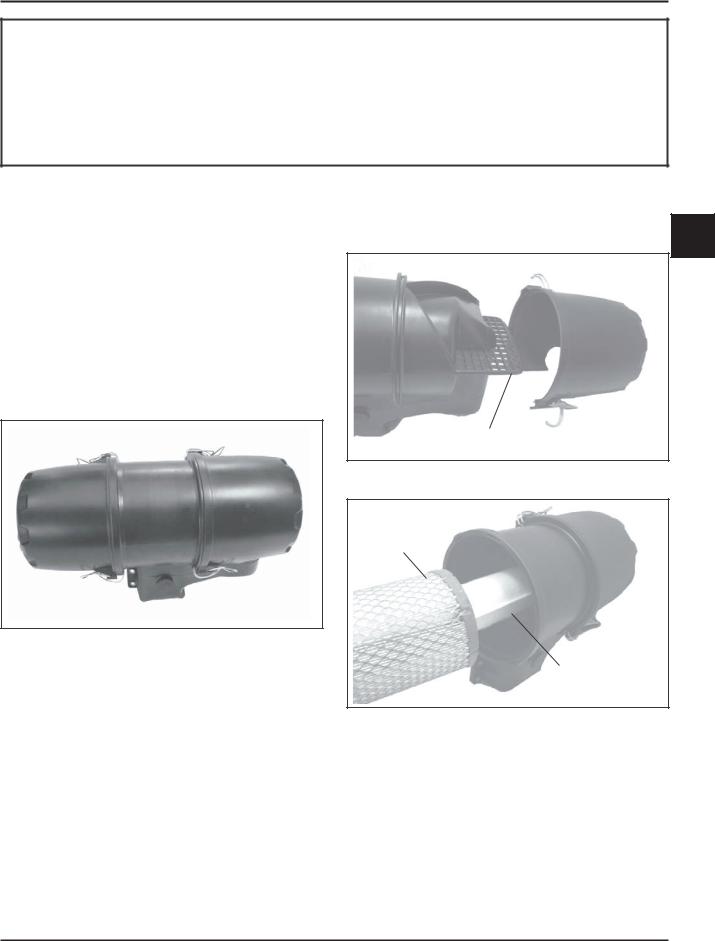
These engines use a heavy-duty style air cleaner as shown in Figure 4-1, consisting of a cylindrical housing attached to the carburetor and intake manifold. The air cleaner housing contains a paper element and inner element, designed for longer service intervals. The system is CARB/EPA certified and the components should not be altered or modified in any way.
Heavy-Duty Style Air Cleaner
Figure 4-1. Heavy-Duty Style Air Cleaner.
Service
Weekly and every 150 hours: Check filter minder (if equipped), unhook the two retaining clips on each end and remove the end caps. Perform inspection of the paper element and inlet screen area.
Seasonally or every 300 hours of operation (more often under extremely dusty or dirty conditions), replace the paper element and check the inner element. Follow these steps.
1.Unhook the two retaining clips on each end and remove the end caps from the air cleaner housing.
2.Check and clean the screen area on the inlet side. Pull the air cleaner paper element out of the housing on opposite side. See Figures 4-2 and 4-3.
4
Inlet Screen
Figure 4-2. Accessing Inlet Screen.
Paper Element
Inner
Element
Figure 4-3. Removing Elements.
3.After the paper element is removed, check the condition of the inner element. It should be replaced whenever it appears dirty, typically every other time the paper element is replaced or every 600 hours. Clean the area around the base of the inner element before removing it, so dirt does not get into the engine.
4.1
Section 4
Air Cleaner and Air Intake System
4.Do not wash the paper element and inner element or use compressed air, this will damage the elements. Replace dirty, bent, or damaged elements with new genuine Kohler elements as required. Handle the new elements carefully; do not use if the sealing surfaces are bent or damaged.
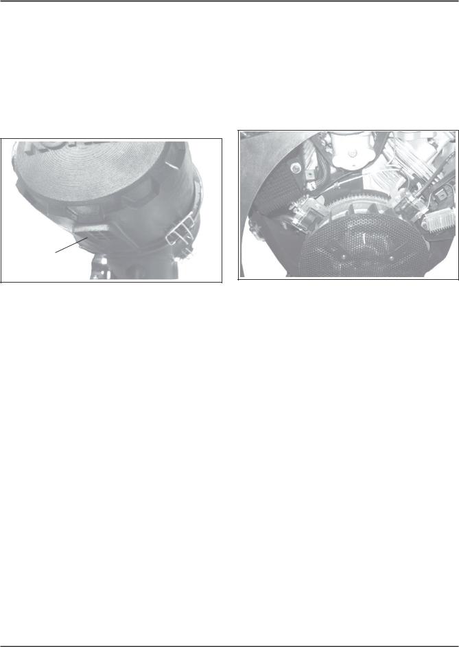
5.Check all parts for wear, cracks, or damage, and that ejector area is clean. See Figure 4-4. Replace any damaged components.
Ejector
Area
Figure 4-4. Ejector Area.
6.Install the new inner element, followed by the paper element. Slide each fully into place in the air cleaner housing.
7.Reinstall the end caps and secure with the retaining clips. See Figure 4-1.
Air Cleaner Components
Whenever the air cleaner cover is removed, or the paper element or inner element are serviced, check the following:
Air Cleaner Housing - Make sure the housing is not damaged or broken and properly secured.
Air Cleaner Inlet - Make sure the air cleaner inlet is secured tightly to the carburetor and not cracked or damaged.
Breather Tube - Make sure the tube is attached to the air cleaner base and the breather cover.
NOTE: Damaged, worn or loose air cleaner components can allow unfiltered air into the engine causing premature wear and failure. Tighten or replace all loose or damaged components.
Air Intake/Cooling System
To ensure proper cooling, make sure the grass screen, cooling fan fins, and external surfaces of the engine are kept clean at all times.
Seasonally or every 150 hours of operation (more often under extremely dusty or dirty conditions), remove the cylinder shrouds and blower housing. Clean the cooling fins and external surfaces as necessary. Make sure all shrouds are reinstalled.
Cylinder
Shroud
Figure 4-5. Removing Shrouds for Cleaning.
4.2

Section 5
Fuel System and Governor
Section 5
Fuel System and Governor
Description
This section covers the standard carbureted fuel system used on these engines. The governor system used is covered at the end of this section.
WARNING: Explosive Fuel!
Gasoline is extremely flammable and its vapors can explode if ignited. Store gasoline only in approved containers, in well ventilated, unoccupied buildings, away from sparks or flames. Do not fill the fuel tank while the engine is hot or running, since spilled fuel could ignite if it comes in contact with hot partsorsparksfromignition.Donotstarttheenginenear spilled fuel. Never use gasoline as a cleaning agent.
Fuel System Components
The typical carbureted fuel system and related components include the following:
•Fuel Tank and Valve
•Fuel Lines
•In-line Fuel Filter
•Fuel Pump
•Carburetor
Operation
The fuel from the tank is moved through the in-line filter and fuel lines by the fuel pump. On engines not equipped with a fuel pump, the fuel tank outlet is located above the carburetor inlet allowing gravity to feed fuel to the carburetor.
Fuel then enters the carburetor float bowl and is drawn into the carburetor body. There, the fuel is mixed with air. This fuel-air mixture is then burned in the engine combustion chamber.
Fuel Recommendations
General Recommendations
Purchase gasoline in small quantities that can be used within 30 days and store only in clean, approved containers. Do not use gasoline left over from the previous season, unless treated with a fuel stabilizer (see Storage in Section 1), to minimize gum deposits and ensure easy starting. Do not use gasoline containing Methanol, or add oil to the gasoline.
Do not overfill the fuel tank. Leave room for the fuel to expand.
Fuel Type
For best results, use only clean, fresh, unleaded gasoline with a pump sticker octane rating of 87 or
higher. In countries using the Research fuel rating 5 method, it should be 90 octane minimum.
Unleaded gasoline is recommended as it leaves less combustion chamber deposits and reduces harmful exhaust emissions. Leaded gasoline is not recommended .
Gasoline/Alcohol blends
Gasohol (up to 10% ethyl alcohol, 90% unleaded gasoline by volume) is approved as a fuel for Kohler engines. Other gasoline/alcohol blends including E20 and E85 are not to be used and not approved. Any failures resulting from use of these fuels will not be warranted.
Gasoline/Ether blends
Methyl Tertiary Butyl Ether (MTBE) and unleaded gasoline blends (up to a maximum of 15% MTBE by volume) are approved as a fuel for Kohler engines. Other gasoline/ether blends are not approved.
Fuel Filter
Most engines are equipped with an in-line fuel filter. Periodically inspect the filter and replace with a genuine Kohler filter seasonally or every 150 operating hours.
Fuel Line
These engines use Low Permeation SAE 30 R7 rated fuel line; certified to meet emission requirements. Standard fuel line may not be used. Order replacement hose by part number through a Kohler Engine Service Dealer.
5.1
Section 5
Fuel System and Governor
Fuel System Tests
When the engine starts hard, or turns over but will not start, it is possible that the problem is in the fuel system. To find out if the fuel system is causing the problem, perform the following tests.
Troubleshooting – Fuel System Related Causes
|
Test |
Conclusion |
1. Check the following: |
|
|
a. |
Make sure the fuel tank contains clean, fresh, |
|
|
proper fuel. |
|
b. |
Make sure the vent in fuel tank cap is open. |
|
c. |
Make sure the fuel valve is open. |
|
d. |
Make sure the fuel lines to fuel pump are |
|
|
secured and in good condition. |
|
|
|
|
2. Check for fuel in the combustion chamber. |
2. If there is fuel at the tip of the spark plug, fuel is |
|
a. |
Disconnect and ground spark plug leads. |
reaching the combustion chamber. |
b. |
Close the choke on the carburetor. |
|
c. |
Crank the engine several times. |
If there is no fuel at the tip of the spark plug, check |
d. |
Remove the spark plug and check for fuel at |
for fuel flow from the fuel tank (Test 3). |
|
the tip. |
|
|
|
|
3. Check for fuel flow from the tank to the fuel pump. |
3. If fuel does flow from the line, check for faulty |
|
a. |
Remove the fuel line from the inlet fitting of |
fuel pump (Test 4). |
|
the fuel pump. |
|
b. |
Hold the line below the bottom of the tank. |
If fuel does not flow from the line, check the fuel |
|
Open the shut-off valve (if so equipped) and |
tank cap vent, fuel pickup screen, in-line filter, |
|
observe flow. |
shut-off valve, and fuel line. Correct any |
|
|
observed problem and reconnect the line. |
|
|
|
4. Check the operation of the fuel pump. |
4. If fuel does flow from the line, check for faulty |
|
a. |
Remove the fuel line from the inlet fitting of |
carburetor. (Refer to the Carburetor portions of |
|
the carburetor. |
this section.) |
b. |
Crank the engine several times and observe |
|
|
flow. |
If fuel does not flow from the line, check for a |
|
|
clogged fuel line. If the fuel line is unobstructed, |
|
|
check for overfilled crankcase and/or oil in pulse |
|
|
line. If none of the checks reveal the cause of the |
|
|
problem, replace the pump. |
|
|
|
Fuel Pump
General
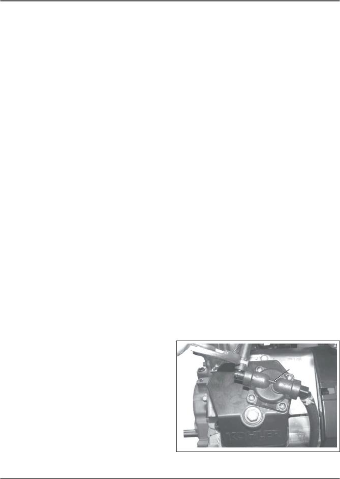
These engines use either a mechanical fuel pump, or optional remote-mounted electric fuel pump assembly. See Figures 5-1 and 5-2. Operation of the mechanical fuel pump occurs by direct lever/pump actuation off rocker arm movement. The pumping action causes the diaphragm on the inside of the pump to pull fuel in on its downward stroke and to push it into the carburetor on its upward stroke, internal check valves prevent fuel from going backward through the pump.
Fuel
Pump
Figure 5-1. Mechanical Fuel Pump.
5.2

Section 5
Fuel System and Governor
Figure 5-2. Optional Electric Fuel Pump.
Fuel Pump - Replacement
Replacing the Mechanical Fuel Pump
The mechanical fuel pump is an integral part of the valve cover assembly and not serviced separately. See Figure 5-1.
1.Disconnect the fuel lines from the inlet and outlet fittings. Note orientation.
2.Follow the procedure for replacing the valve cover (see Sections 8 and 10).
3.Reconnect the fuel lines to the inlet and outlet fittings and secure with the clamps.
Carburetor
General
Engines in this series are equipped with a Keihin BK two-barrel, side-draft carburetor with fixed main jets on a matching intake manifold. The carburetor features a self-relieving choke, serviceable slow jets, main jets, bowl drain and a fuel shutdown solenoid. See Figure 5-3.
WARNING: Explosive Fuel
Gasoline is extremely flammable and its vapors can explode if ignited. Store gasoline only in approved containers, in well ventilated, unoccupied buildings, away from sparks or flames. Do not fill the fuel tank while the engine is hot or running, since spilled fuel could ignite if it comes in contact with hot partsorsparksfromignition.Donotstarttheenginenear spilled fuel. Never use gasoline as a cleaning agent.
Self-Relieving |
Low Idle Fuel |
Choke |
Adjustments |
|
(With Limiters) |
|
Slow Jets |
|
Bowl Vent |
|
Fuel Shut-Off |
|
||
|
Solenoid |
|
||
|
|
|||
|
Figure 5-3. Keihin Two-Barrel Carburetor. |
|
|
|
Troubleshooting Checklist |
|
|||
5 |
||||
When the engine starts hard, runs roughly, or stalls |
||||
at low idle speed, check the following areas before |
||||
|
||||
adjusting or disassembling the carburetor. |
|
|||
•Make sure the fuel tank is filled with clean, fresh gasoline.
•Make sure the fuel tank cap vent is not blocked and that it is operating properly.
•Make sure fuel is reaching the carburetor. This includes checking the fuel shut-off valve, fuel tank filter screen, in-line fuel filter, fuel lines and fuel pump for restrictions or faulty components as necessary.
•Make sure the air cleaner base and carburetor are securely fastened to the engine using gaskets in good condition.
•Make sure the air cleaner element (including precleaner if equipped) is clean and all air cleaner components are fastened securely.
•Make sure the ignition system, governor system, exhaust system, and throttle and choke controls are operating properly.
If the engine is hard-starting, runs roughly, or stalls at low idle speed, it may be necessary to adjust or service the carburetor.
5.3
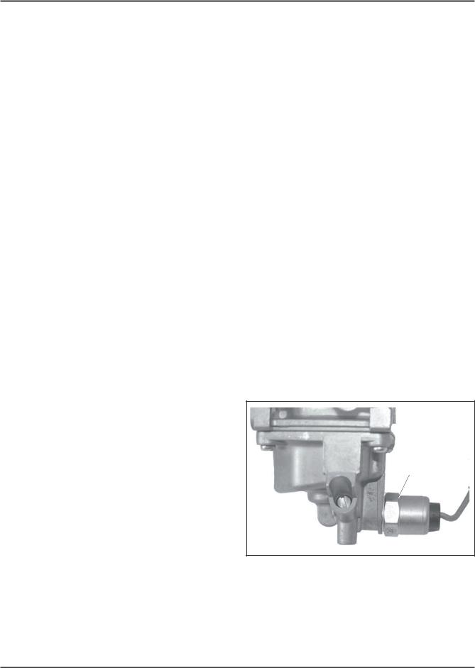
Section 5
Fuel System and Governor
Troubleshooting – Carburetor Related Causes
Condition |
|
Possible Cause/Probable Remedy |
1. Engine starts hard, runs roughly, |
1. |
Low idle fuel mixture (some models)/speed improperly adjusted. |
or stalls at idle speed. |
|
Adjust the low idle speed tab, then adjust the low idle fuel needle. |
|
|
|
2. Engine runs rich (indicated by |
2a. |
Clogged air cleaner. Clean or replace. |
black, sooty exhaust smoke, |
b. |
Choke partially closed during operation. Check the choke lever/ |
misfiring, loss of speed and power, |
|
linkage to ensure choke is operating properly. |
governor hunting, or excessive |
c. |
Low idle fuel mixture is improperly adjusted. Adjust low idle |
throttle opening). |
|
fuel needle (some models). |
|
d. |
Float level is set too high. Adjust float according to Float |
|
|
Replacement Procedure. |
|
e. |
Dirt under the fuel inlet needle. Remove needle; clean needle and |
|
|
seat and blow with compressed air. |
|
f. |
Bowl vent or air bleeds plugged. Remove low idle fuel adjusting |
|
|
needle. Clean vent, ports, and air bleeds. Blow out all passages |
|
|
with compressed air. |
|
g. |
Leaky, cracked or damaged float. Submerge float to check for |
|
|
leaks. |
|
|
|
3. Engine runs lean (indicated by |
3a. |
Low idle fuel mixture is improperly adjusted. Adjust low idle |
misfiring, loss of speed and power, |
|
fuel needle (some models). |
governor hunting, or excessive |
b. |
Float level is set too low. Adjust float according to Float |
throttle opening). |
|
Replacement Procedure. |
|
c. |
Idle holes plugged; dirt in fuel delivery channels. Remove low |
|
|
idle fuel adjusting needle. Clean main fuel jet and all passages; |
|
|
blow out with compressed air. |
|
|
|
4. Fuel leaks from carburetor. |
4a. |
Float level set too high. See Remedy 2d. |
|
b. |
Dirt under fuel inlet needle. See Remedy 2e. |
|
c. |
Bowl vents plugged. Blow out with compressed air. |
|
d. |
Carburetor bowl gasket leaks. Replace gasket. |
|
|
|
High Altitude Operation
When operating the engine at altitudes of 1500 m (5000 ft.) and above, the fuel mixture tends to get over-rich. This can cause conditions such as black, sooty exhaust smoke, misfiring, loss of speed and power, poor fuel economy, and poor or slow governor response.
To compensate for the effects of high altitude, special high altitude jet kits are available. The kits include new main jets, slow jets (where applicable), necessary gaskets, and O-Rings. Refer to the parts manual for the correct kit number.
Fuel Shut-off Solenoid
Most carburetors are equipped with a fuel shut-off solenoid. The solenoid is attached to the fuel bowl. See Figure 5-4. The solenoid has a spring-loaded pin that retracts when 12 volts is applied to the lead, allowing fuel flow to the main jets. When current is removed the pin extends blocking the fuel flow.
Fuel Shut-Off
Solenoid
Figure 5-4. Fuel Shut-off Solenoid.
Below is a simple test, made with the engine off, that can determine if the solenoid is functioning properly:
1.Shut off fuel and remove the solenoid from the carburetor. When the solenoid is loosened and removed, gas will leak out of the carburetor.
5.4

Section 5
Fuel System and Governor
Have a container ready to catch the fuel.
2.Wipe the tip of the solenoid with a shop towel or blow it off with compressed air, to remove any remaining fuel. Take the solenoid to a location with good ventilation and no fuel vapors present. You will also need a 12 volt power source that can be switched on and off.
3.Be sure the power source is switched off. Connect the positive power source lead to the red lead of the solenoid. Connect the negative power source lead to the solenoid body.
4.Turn the power source on and observe the pin in the center of the solenoid. The pin should retract with the power on and return to its original position with the power off. Test several times to verify operation.
Carburetor Details
The Keihin BK two-barrel carburetor is a side-draft design. The circuits within the carburetor function as described following:
Float Circuit:
The fuel level in the bowl is maintained by the float and fuel inlet needle. The buoyant force of the float stops fuel flow when the engine is at rest. When fuel is being consumed, the float will drop and fuel pressure will push the inlet needle away from the seat, allowing more fuel to enter the bowl. When demand ceases, the buoyant force of the float will again overcome the fuel pressure, rising to the predetermined setting and stop the flow.
Slow & Mid-Range Circuit:
At low speeds the engine operates only on the slow circuit. As a metered amount of air is drawn through the slow air bleed jets, fuel is drawn through the two main jets and further metered through the slow jets. Air and fuel are mixed in the body of the slow jet and exit to the transfer port. From the transfer port the air fuel mixture is delivered to the idle progression chamber. From the idle progression chamber the air fuel mixture is metered through the idle port passages. At low idle when the vacuum signal is weak, the air/fuel mixture is controlled by the setting of the idle fuel adjusting screws. This mixture is then mixed with the main body of air and delivered to the engine. As the throttle plate opening increases, greater amounts of air/fuel mixture are drawn in through the fixed and metered idle progression holes. As the throttle plate opens further the vacuum signal becomes great enough so the main circuit begins to work.
Main (High-Speed) Circuit:
At high speeds/loads the engine operates on the main circuit. As a metered amount of air is drawn through the four air jets, fuel is drawn through the main jets. The air and fuel are mixed in the main nozzles and then enter the main body of airflow, where further mixing of the fuel and air occurs. This mixture is then delivered to the combustion chamber. The carburetor has a fixed main circuit; no adjustment is possible.
Carburetor Adjustments
Adjustment
NOTE: Carburetor adjustments should be made only after the engine has warmed up.
The carburetor is designed to deliver the correct fuel- to-air mixture to the engine under all operating 5 conditions. The main fuel jet is calibrated at the
factory and is not adjustable*. The idle fuel adjusting needles are also set at the factory and normally do not need adjustment.
*NOTE: Engines operating at altitudes above approximately 1500 m (5000 ft.) may require a special high altitude main jet. Refer to High Altitude Operation later in this section.
If, however, the engine is hard-starting or does not operate properly, it may be necessary to adjust or service the carburetor.
Low Idle Speed (RPM) Adjustment
1.Low Idle Speed (RPM) Setting: Place the throttle control in the idle or slow position. Set the low idle speed approximately 300 RPM* less than the intended or specified Governed Idle Speed, by turning the low idle speed adjusting screw in or out. Check the speed using a tachometer.
IMPORTANT: The Governed Idle Speed Adjustment must follow any resetting of the Low Idle Speed.
*NOTE: The actual low idle speed depends on the application. Refer to the equipment manufacturer’s recommendations. The low idle speed for basic engines is 1200 RPM. To ensure best results when setting the low idle fuel needle, the low idle speed should be 1200 RPM (± 75 RPM).
5.5
 Loading...