


Operation
Residential/Commercial Generator Sets
Models:
8/10/12RESV
8/10/12RESVL
Controllers:
RDC2
DC2
TP-6880 10/14a
California Proposition 65
WARNING
Engine exhaust from this product contains chemicals known to the State of California to cause cancer, birth defects, or other reproductive harm.
Product Identification Information
Product identification numbers determine service parts. Record the product identification numbers in the spaces below immediately after unpacking the products so that the numbers are readily available for future reference. Record field-installed kit numbers after installing the kits.
Generator Set Identification Numbers
Record the product identification numbers from the generator set nameplate(s).
Model Designation
Specification Number
Serial Number
Accessory Number |
|
Accessory Description |
|
|
|
|
|
|
|
|
|
|
|
|
|
|
|
|
|
|
|
|
|
|
|
|
|
|
|
|
|
|
|
|
|
|
|
|
|
|
|
|
|
|
|
|
|
|
|
|
|
|
|
|
|
|
Controller Identification
Record the controller description from the generator set operation manual, spec sheet, or sales invoice.
Controller Description
Engine Identification
Record the product identification information from the engine nameplate.
Manufacturer Model Designation Serial Number

|
Table of Contents |
Safety Precautions and Instructions . . . . . . . . . . . . . . . . . . . . . . . . . . . . . . . . . . . . . . . |
. . . . . . . . . . . . . . . . . . 5 |
Introduction . . . . . . . . . . . . . . . . . . . . . . . . . . . . . . . . . . . . . . . . . . . . . . . . . . . . . . . . . . . . . |
. . . . . . . . . . . . . . . . . . 9 |
Service Assistance . . . . . . . . . . . . . . . . . . . . . . . . . . . . . . . . . . . . . . . . . . . . . . . . . . . . . . . . |
. . . . . . . . . . . . . . . . . 11 |
Section 1 Descriptions and Service Views . . . . . . . . . . . . . . . . . . . . . . . . . . . . . . . . . . |
. . . . . . . . . . . . . . . . . 13 |
1.1 Introduction . . . . . . . . . . . . . . . . . . . . . . . . . . . . . . . . . . . . . . . . . . . . . . . . . . . . . . . . . . . 13
1.2 Engine . . . . . . . . . . . . . . . . . . . . . . . . . . . . . . . . . . . . . . . . . . . . . . . . . . . . . . . . . . . . . . . 13
1.3 Generator Set Enclosure . . . . . . . . . . . . . . . . . . . . . . . . . . . . . . . . . . . . . . . . . . . . . . . 13
1.4 Alternator . . . . . . . . . . . . . . . . . . . . . . . . . . . . . . . . . . . . . . . . . . . . . . . . . . . . . . . . . . . . . 13
1.5 Transfer Switch . . . . . . . . . . . . . . . . . . . . . . . . . . . . . . . . . . . . . . . . . . . . . . . . . . . . . . . . 13
1.6 Controllers . . . . . . . . . . . . . . . . . . . . . . . . . . . . . . . . . . . . . . . . . . . . . . . . . . . . . . . . . . . . 13
1.7 OnCue Plus Generator Management System . . . . . . . . . . . . . . . . . . . . . . . . . . . . . . 15
1.8 Accessories . . . . . . . . . . . . . . . . . . . . . . . . . . . . . . . . . . . . . . . . . . . . . . . . . . . . . . . . . . . 16
1.8.1 Carburetor Heater . . . . . . . . . . . . . . . . . . . . . . . . . . . . . . . . . . . . . . . . . . . . . 16
1.8.2 Programmable Interface Module (PIM) . . . . . . . . . . . . . . . . . . . . . . . . . . . 16
1.8.3 Load Control Module (LCM) . . . . . . . . . . . . . . . . . . . . . . . . . . . . . . . . . . . . . 16
1.8.4 Load Shed Kit . . . . . . . . . . . . . . . . . . . . . . . . . . . . . . . . . . . . . . . . . . . . . . . . . 16
1.9 Service Views . . . . . . . . . . . . . . . . . . . . . . . . . . . . . . . . . . . . . . . . . . . . . . . . . . . . . . . . . 17
Section 2 Generator Set Operation . . . . . . . . . . . . . . . . . . . . . . . . . . . . . . . . . . . . . . . . . . . . . . . . . . . . . . . . . . |
19 |
||
2.1 |
Prestart Checklist . . . . . . . . . . . . . . . . . . . . . . . . . . . . . . . . . . . . . . . . . . . . . . . . . . . . . . |
19 |
|
2.2 |
Exercising the Generator Set . . . . . . . . . . . . . . . . . . . . . . . . . . . . . . . . . . . . . . . . . . . . |
21 |
|
2.3 |
Generator Set Operation . . . . . . . . . . . . . . . . . . . . . . . . . . . . . . . . . . . . . . . . . . . . . . . . |
21 |
|
|
2.3.1 |
Local Starting and Stopping . . . . . . . . . . . . . . . . . . . . . . . . . . . . . . . . . . . . . |
21 |
|
2.3.2 |
Automatic Starting and Stopping . . . . . . . . . . . . . . . . . . . . . . . . . . . . . . . . . |
21 |
|
2.3.3 |
Remote Starting and Stopping . . . . . . . . . . . . . . . . . . . . . . . . . . . . . . . . . . . |
21 |
|
2.3.4 |
Engine Start Crank Cycle . . . . . . . . . . . . . . . . . . . . . . . . . . . . . . . . . . . . . . . |
21 |
|
2.3.5 |
Engine Cooldown . . . . . . . . . . . . . . . . . . . . . . . . . . . . . . . . . . . . . . . . . . . . . . |
21 |
|
2.3.6 |
Automatic Operation with Model RXT Transfer Switch . . . . . . . . . . . . . . |
21 |
|
2.3.7 |
Automatic Operation with Other Transfer Switches . . . . . . . . . . . . . . . . . |
22 |
2.4 |
Exercise |
. . . . . . . . . . . . . . . . . . . . . . . . . . . . . . . . . . . . . . . . . . . . . . . . . . . . . . . . . . . . . . |
22 |
|
2.4.1 |
Setting the Exerciser . . . . . . . . . . . . . . . . . . . . . . . . . . . . . . . . . . . . . . . . . . . |
22 |
|
2.4.2 |
Unloaded Cycle Exercise with Complete System Diagnostics . . . . . . . . |
22 |
|
2.4.3 |
Unloaded Full-Speed Exercise . . . . . . . . . . . . . . . . . . . . . . . . . . . . . . . . . . |
23 |
|
2.4.4 |
Loaded Full-Speed Exercise (with RXT only) . . . . . . . . . . . . . . . . . . . . . . |
23 |
|
2.4.5 |
Power Failure During Exercise Cycle . . . . . . . . . . . . . . . . . . . . . . . . . . . . . |
23 |
2.5 |
Faults . . |
. . . . . . . . . . . . . . . . . . . . . . . . . . . . . . . . . . . . . . . . . . . . . . . . . . . . . . . . . . . . . . |
24 |
|
2.5.1 |
Warnings . . . . . . . . . . . . . . . . . . . . . . . . . . . . . . . . . . . . . . . . . . . . . . . . . . . . . |
24 |
|
2.5.2 |
Shutdowns . . . . . . . . . . . . . . . . . . . . . . . . . . . . . . . . . . . . . . . . . . . . . . . . . . . . |
24 |
|
2.5.3 |
ATS Communication Errors . . . . . . . . . . . . . . . . . . . . . . . . . . . . . . . . . . . . . |
24 |
|
2.5.4 |
Resetting the Controller after a Fault Shutdown . . . . . . . . . . . . . . . . . . . . |
24 |
2.6 |
Generator Enclosure Thermostat . . . . . . . . . . . . . . . . . . . . . . . . . . . . . . . . . . . . . . . . |
27 |
|
Section 3 RDC2 Controller Operation . . . . . . . . . . . . . . . . . . . . . . . . . . . . . . . . . . . . . . . . . . . . . . . . . . . . . . . |
29 |
||
3.1 |
RDC2 Generator Set/ Transfer Switch Controller . . . . . . . . . . . . . . . . . . . . . . . . . . . |
29 |
|
3.2 |
Controls and Indicators . . . . . . . . . . . . . . . . . . . . . . . . . . . . . . . . . . . . . . . . . . . . . . . . . |
29 |
|
|
3.2.1 |
Controller Keypad . . . . . . . . . . . . . . . . . . . . . . . . . . . . . . . . . . . . . . . . . . . . . |
30 |
|
3.2.2 |
LED Indicators . . . . . . . . . . . . . . . . . . . . . . . . . . . . . . . . . . . . . . . . . . . . . . . . |
30 |
|
3.2.3 |
LCD Display . . . . . . . . . . . . . . . . . . . . . . . . . . . . . . . . . . . . . . . . . . . . . . . . . . |
31 |
3.3 |
Controller Power . . . . . . . . . . . . . . . . . . . . . . . . . . . . . . . . . . . . . . . . . . . . . . . . . . . . . . . |
32 |
|
3.4 |
Battery Charging . . . . . . . . . . . . . . . . . . . . . . . . . . . . . . . . . . . . . . . . . . . . . . . . . . . . . . |
32 |
|
3.5 |
Changing Settings . . . . . . . . . . . . . . . . . . . . . . . . . . . . . . . . . . . . . . . . . . . . . . . . . . . . . |
32 |
|
3.6 |
Setting the Exerciser . . . . . . . . . . . . . . . . . . . . . . . . . . . . . . . . . . . . . . . . . . . . . . . . . . . |
34 |
|
|
3.6.1 Setting the Exerciser at Controller Power-up . . . . . . . . . . . . . . . . . . . . . . |
34 |
|
|
3.6.2 Changing the Exercise Settings . . . . . . . . . . . . . . . . . . . . . . . . . . . . . . . . . . |
34 |
|
3.7 |
RDC2 Controller Menus . . . . . . . . . . . . . . . . . . . . . . . . . . . . . . . . . . . . . . . . . . . . . . . . |
36 |
|
3.8 |
Main Menu . . . . . . . . . . . . . . . . . . . . . . . . . . . . . . . . . . . . . . . . . . . . . . . . . . . . . . . . . . . . |
36 |
|
3.9 |
Overview Menu . . . . . . . . . . . . . . . . . . . . . . . . . . . . . . . . . . . . . . . . . . . . . . . . . . . . . . . . |
37 |
|
3.10 |
Engine Metering Menu . . . . . . . . . . . . . . . . . . . . . . . . . . . . . . . . . . . . . . . . . . . . . . . . . |
37 |
|
3.11 |
Generator Metering Menu . . . . . . . . . . . . . . . . . . . . . . . . . . . . . . . . . . . . . . . . . . . . . . . |
38 |
|
3.12 |
Generator Set Information Menu . . . . . . . . . . . . . . . . . . . . . . . . . . . . . . . . . . . . . . . . . |
39 |
|
3.13 |
Genset Run Time Menu . . . . . . . . . . . . . . . . . . . . . . . . . . . . . . . . . . . . . . . . . . . . . . . . |
39 |
|
TP-6880 10/14 |
Table of Contents |

Table of Contents, continued
3.14 |
Genset System Menu . . . . . . . . . . . . . . . . . . . . . . . . . . . . . . . . . . . . . . . . . . . . . . . . . . |
40 |
|
3.15 |
ATS Status Menu . . . . . . . . . . . . . . . . . . . . . . . . . . . . . . . . . . . . . . . . . . . . . . . . . . . . . . |
41 |
|
3.16 |
ATS Configuration Menu . . . . . . . . . . . . . . . . . . . . . . . . . . . . . . . . . . . . . . . . . . . . . . . . |
42 |
|
3.17 |
Date and Time Menu . . . . . . . . . . . . . . . . . . . . . . . . . . . . . . . . . . . . . . . . . . . . . . . . . . . |
43 |
|
3.18 |
Networking Information Menus . . . . . . . . . . . . . . . . . . . . . . . . . . . . . . . . . . . . . . . . . . |
43 |
|
|
3.18.1 |
Networking Status Submenu . . . . . . . . . . . . . . . . . . . . . . . . . . . . . . . . . . . . |
44 |
|
3.18.2 |
Networking Configuration Submenu (OnCue Plus Password) . . . . . . . . |
45 |
|
3.18.3 |
RBUS Information . . . . . . . . . . . . . . . . . . . . . . . . . . . . . . . . . . . . . . . . . . . . . |
47 |
|
3.18.4 |
Remote Devices Submenu . . . . . . . . . . . . . . . . . . . . . . . . . . . . . . . . . . . . . . |
48 |
3.19 |
Programmable Interface Module (PIM) Status Menu . . . . . . . . . . . . . . . . . . . . . . . . |
49 |
|
3.20 |
Load Control Module (LCM) or Load Shed Kit Menus . . . . . . . . . . . . . . . . . . . . . . . |
50 |
|
3.21 |
Event Log . . . . . . . . . . . . . . . . . . . . . . . . . . . . . . . . . . . . . . . . . . . . . . . . . . . . . . . . . . . . |
51 |
|
Section 4 DC2 Controller Operation . . . . . . . . . . . . . . . . . . . . . . . . . . . . . . . . . . . . . . . . . . . . . . . . . . . . . . . . . |
53 |
||
4.1 |
DC2 Generator Set/ Transfer Switch Controller . . . . . . . . . . . . . . . . . . . . . . . . . . . . |
53 |
|
4.2 |
Controls and Indicators . . . . . . . . . . . . . . . . . . . . . . . . . . . . . . . . . . . . . . . . . . . . . . . . . |
53 |
|
|
4.2.1 |
Controller Keypad . . . . . . . . . . . . . . . . . . . . . . . . . . . . . . . . . . . . . . . . . . . . . |
54 |
|
4.2.2 |
LED Indicators . . . . . . . . . . . . . . . . . . . . . . . . . . . . . . . . . . . . . . . . . . . . . . . . |
54 |
|
4.2.3 |
LCD Display . . . . . . . . . . . . . . . . . . . . . . . . . . . . . . . . . . . . . . . . . . . . . . . . . . |
55 |
4.3 |
Controller Power . . . . . . . . . . . . . . . . . . . . . . . . . . . . . . . . . . . . . . . . . . . . . . . . . . . . . . . |
55 |
|
4.4 |
Battery Charging . . . . . . . . . . . . . . . . . . . . . . . . . . . . . . . . . . . . . . . . . . . . . . . . . . . . . . |
55 |
|
4.5 |
Exercise |
. . . . . . . . . . . . . . . . . . . . . . . . . . . . . . . . . . . . . . . . . . . . . . . . . . . . . . . . . . . . . . |
56 |
|
4.5.1 |
Exercise Modes . . . . . . . . . . . . . . . . . . . . . . . . . . . . . . . . . . . . . . . . . . . . . . . |
56 |
|
4.5.2 |
Setting the Exerciser . . . . . . . . . . . . . . . . . . . . . . . . . . . . . . . . . . . . . . . . . . . |
56 |
|
4.5.3 |
Exerciser Reset . . . . . . . . . . . . . . . . . . . . . . . . . . . . . . . . . . . . . . . . . . . . . . . |
56 |
4.6 |
Event Log . . . . . . . . . . . . . . . . . . . . . . . . . . . . . . . . . . . . . . . . . . . . . . . . . . . . . . . . . . . . |
56 |
|
4.7 |
Maintenance Timer . . . . . . . . . . . . . . . . . . . . . . . . . . . . . . . . . . . . . . . . . . . . . . . . . . . . |
57 |
|
4.8 |
OnCue Plus Password . . . . . . . . . . . . . . . . . . . . . . . . . . . . . . . . . . . . . . . . . . . . . . . . . |
57 |
|
Section 5 Scheduled Maintenance . . . . . . . . . . . . . . . . . . . . . . . . . . . . . . . . . . . . . . . . . . . . . . . . . . . . . . . . . . |
59 |
||
5.1 |
Scheduled Maintenance . . . . . . . . . . . . . . . . . . . . . . . . . . . . . . . . . . . . . . . . . . . . . . . . |
60 |
|
|
5.1.1 |
Service Schedule . . . . . . . . . . . . . . . . . . . . . . . . . . . . . . . . . . . . . . . . . . . . . . |
61 |
5.2 |
Lubrication System . . . . . . . . . . . . . . . . . . . . . . . . . . . . . . . . . . . . . . . . . . . . . . . . . . . . |
62 |
|
|
5.2.1 |
Low Oil Pressure Shutdown . . . . . . . . . . . . . . . . . . . . . . . . . . . . . . . . . . . . . |
62 |
|
5.2.2 |
Oil Check . . . . . . . . . . . . . . . . . . . . . . . . . . . . . . . . . . . . . . . . . . . . . . . . . . . . . |
62 |
|
5.2.3 |
Engine Oil Recommendation . . . . . . . . . . . . . . . . . . . . . . . . . . . . . . . . . . . . |
62 |
|
5.2.4 |
Oil Change Procedure . . . . . . . . . . . . . . . . . . . . . . . . . . . . . . . . . . . . . . . . . . |
62 |
|
5.2.5 |
Resetting the Maintenance Timer . . . . . . . . . . . . . . . . . . . . . . . . . . . . . . . . |
64 |
5.3 |
Spark Plugs . . . . . . . . . . . . . . . . . . . . . . . . . . . . . . . . . . . . . . . . . . . . . . . . . . . . . . . . . . . |
64 |
|
5.4 |
Air Cleaner Service . . . . . . . . . . . . . . . . . . . . . . . . . . . . . . . . . . . . . . . . . . . . . . . . . . . . |
65 |
|
|
5.4.1 |
Air Cleaner, 8RESV/RESVL Models . . . . . . . . . . . . . . . . . . . . . . . . . . . . . . |
65 |
|
5.4.2 |
Air Cleaner, 10/12RESV/RESVL Models . . . . . . . . . . . . . . . . . . . . . . . . . . |
66 |
5.5 |
Cooling System . . . . . . . . . . . . . . . . . . . . . . . . . . . . . . . . . . . . . . . . . . . . . . . . . . . . . . . |
66 |
|
5.6 |
Exhaust System . . . . . . . . . . . . . . . . . . . . . . . . . . . . . . . . . . . . . . . . . . . . . . . . . . . . . . . |
67 |
|
5.7 |
Battery . |
. . . . . . . . . . . . . . . . . . . . . . . . . . . . . . . . . . . . . . . . . . . . . . . . . . . . . . . . . . . . . . |
68 |
5.8 |
Storage Procedure . . . . . . . . . . . . . . . . . . . . . . . . . . . . . . . . . . . . . . . . . . . . . . . . . . . . . |
69 |
|
|
5.8.1 |
Lubricating System . . . . . . . . . . . . . . . . . . . . . . . . . . . . . . . . . . . . . . . . . . . . |
69 |
|
5.8.2 |
Fuel System . . . . . . . . . . . . . . . . . . . . . . . . . . . . . . . . . . . . . . . . . . . . . . . . . . |
69 |
|
5.8.3 |
Cylinder Lubrication . . . . . . . . . . . . . . . . . . . . . . . . . . . . . . . . . . . . . . . . . . . . |
69 |
|
5.8.4 |
Exterior Preparation . . . . . . . . . . . . . . . . . . . . . . . . . . . . . . . . . . . . . . . . . . . . |
69 |
|
5.8.5 |
Battery . . . . . . . . . . . . . . . . . . . . . . . . . . . . . . . . . . . . . . . . . . . . . . . . . . . . . . . |
69 |
Section 6 Troubleshooting . . . |
. . . . . . . . . . . . . . . . . . . . . . . . . . . . . . . . . . . . . . . . . . . . . . . . . . . . . . . . . . . . . . |
71 |
|
6.1 |
Introduction . . . . . . . . . . . . . . . . . . . . . . . . . . . . . . . . . . . . . . . . . . . . . . . . . . . . . . . . . . . |
71 |
|
6.2 |
USB Port . . . . . . . . . . . . . . . . . . . . . . . . . . . . . . . . . . . . . . . . . . . . . . . . . . . . . . . . . . . . . |
71 |
|
6.3 |
Fault Messages . . . . . . . . . . . . . . . . . . . . . . . . . . . . . . . . . . . . . . . . . . . . . . . . . . . . . . . |
71 |
|
6.4 |
Circuit Protection . . . . . . . . . . . . . . . . . . . . . . . . . . . . . . . . . . . . . . . . . . . . . . . . . . . . . . |
71 |
|
|
6.4.1 |
Controller Internal Circuit Protection . . . . . . . . . . . . . . . . . . . . . . . . . . . . . . |
71 |
|
6.4.2 |
Line Circuit Breaker . . . . . . . . . . . . . . . . . . . . . . . . . . . . . . . . . . . . . . . . . . . . |
71 |
|
6.4.3 |
Auxiliary Winding Circuit Breaker . . . . . . . . . . . . . . . . . . . . . . . . . . . . . . . . |
71 |
6.5 |
Troubleshooting . . . . . . . . . . . . . . . . . . . . . . . . . . . . . . . . . . . . . . . . . . . . . . . . . . . . . . . |
72 |
|
Appendix A Abbreviations . . . . . . |
. . . . . . . . . . . . . . . . . . . . . . . . . . . . . . . . . . . . . . . . . . . . . . . . . . . . . . . . . . . . . |
73 |
|
Table of Contents |
TP-6880 10/14 |
Safety Precautions and Instructions
IMPORTANT SAFETY INSTRUCTIONS.
Electromechanical equipment, including generator sets, transfer switches, switchgear, and accessories, can cause bodily harm and pose life-threatening danger when improperly installed, operated, or maintained. To prevent accidents be aware of potential dangers and act safely. Read and follow all safety precautions and instructions. SAVE THESE INSTRUCTIONS.
This manual has several types of safety precautions and instructions: Danger, Warning, Caution, and Notice.
DANGER
Danger indicates the presence of a hazard that will cause severe personal injury, death, or substantial property damage.
WARNING
Warning indicates the presence of a hazard that can cause severe personal injury, death, or substantial property damage.
CAUTION
Caution indicates the presence of a hazard that will or can cause minor personal injury or property damage.
NOTICE
Notice communicates installation, operation, or maintenance information that is safety related but not hazard related.
Safety decals affixed to the equipment in prominent places alert the operator or service technician to potential hazards and explain how to act safely. The decals are shown throughout this publication to improve operator recognition. Replace missing or damaged decals.
Accidental Starting
WARNING
Accidental starting.
Can cause severe injury or death.
Disconnect the battery cables before working on the generator set. Remove the negative (--) lead first when disconnecting the battery. Reconnect the negative (--) lead last when reconnecting the battery.
Disabling the generator set. Accidental starting can cause severe injury or death. Before working on the generator set or equipment connected to the set, disable the generator set as follows:
(1)Press the generator set off/reset button to shut down the generator set.
(2)Disconnect the power to the battery charger, if equipped. (3) Remove the battery cables, negative (--) lead first. Reconnect the negative (--) lead last when reconnecting the battery. Follow these precautions to prevent the starting of the generator set by the remote start/stop switch.
Battery
WARNING
Sulfuric acid in batteries.
Can cause severe injury or death.
Wear protective goggles and clothing. Battery acid may cause blindness and burn skin.
WARNING
Explosion.
Can cause severe injury or death. Relays in the battery charger cause arcs or sparks.
Locate the battery in a well-ventilated area. Isolate the battery charger from explosive fumes.
Battery electrolyte is a diluted sulfuric acid. Battery acid can cause severe injury or death. Battery acid can cause blindness and burn skin. Always wear splashproof safety goggles, rubber gloves, and boots when servicing the battery. Do not open a sealed battery or mutilate the battery case. If battery acid splashes in the eyes or on the skin, immediately flush the affected area for 15 minutes with large quantities of clean water. Seek immediate medical aid in the case of eye contact. Never add acid to a battery after placing the battery in service, as this may result in hazardous spattering of battery acid.
Battery acid cleanup. Battery acid can cause severe injury or death.
Battery acid is electrically conductive and corrosive. Add 500 g (1 lb.) of bicarbonate of soda (baking soda) to a container with 4 L (1 gal.) of water and mix the neutralizing solution. Pour the neutralizing solution on the spilled battery acid and continue to add the neutralizing solution to the spilled battery acid until all evidence of a chemical reaction (foaming) has ceased. Flush the resulting liquid with water and dry the area.
TP-6880 10/14 |
Safety Precautions and Instructions |
5 |
Battery gases. Explosion can cause severe injury or death. Battery gases can cause an explosion. Do not smoke or permit flames or sparks to occur near a battery at any time, particularly when it is charging. Do not dispose of a battery in a fire. To prevent burns and sparks that could cause an explosion, avoid touching the battery terminals with tools or other metal objects. Remove all jewelry before servicing the equipment. Discharge static electricity from your body before touching batteries by first touching a grounded metal surface away from the battery. To avoid sparks, do not disturb the battery charger connections while the battery is charging. Always turn the battery charger off before disconnecting the battery connections. Ventilate the compartments containing batteries to prevent accumulation of explosive gases.
Battery short circuits. Explosion can cause severe injury or death.
Short circuits can cause bodily injury and/or equipment damage. Disconnect the battery before generator set installation or maintenance. Remove all jewelry before servicing the equipment. Use tools with insulated handles. Remove the negative (--) lead first when disconnecting the battery. Reconnect the negative (--) lead last when reconnecting the battery. Never connect the negative (--) battery cable to the positive (+) connection terminal of the starter solenoid. Do not test the battery condition by shorting the terminals together.
Engine Backfire/Flash
Fire
WARNING
Fire.
Can cause severe injury or death.
Do not smoke or permit flames or sparks near fuels or the fuel system.
Servicing the air cleaner. A sudden backfire can cause severe injury or death. Do not operate the generator set with the air cleaner removed.
Servicing the fuel system. A flash fire can cause severe injury or death.
Do not smoke or permit flames or sparks near the carburetor, fuel line, fuel filter, fuel pump, or other potential sources of spilled fuels or fuel vapors. Catch fuels in an approved container when removing the fuel line or carburetor.
Combustible materials. A fire can cause severe injury or death.
Generator set engine fuels and fuel vapors are flammable and explosive. Handle these materials carefully to minimize the risk of fire or explosion. Equip the compartment or nearby area with a fully charged fire extinguisher. Select a fire extinguisher rated ABC or BC for electrical fires or as recommended by the local fire code or an authorized agency. Train all personnel on fire extinguisher operation and fire prevention procedures.
Exhaust System
WARNING
Carbon monoxide.
Can cause severe nausea, fainting, or death.
The exhaust system must be leakproof and routinely inspected.
Generator set operation. Carbon monoxide can cause severe nausea, fainting, or death. Carbon monoxide is an odorless, colorless, tasteless, nonirritating gas that can cause death if inhaled for even a short time. Avoid breathing exhaust fumes when working on or near the generator set. Never operate the generator set inside a building. Never operate the generator set where exhaust gas could seep inside or be drawn into a potentially occupied building through windows, air intake vents, or other openings.
Carbon monoxide detectors. Carbon monoxide can cause severe nausea, fainting, or death. Install carbon monoxide detectors on each level of any building adjacent to the generator set. Locate the detectors to adequately warn the building’s occupants of the presence of carbon monoxide. Keep the detectors operational at all times. Periodically test and replace the carbon monoxide detectors according to the manufacturer’s instructions.
Carbon monoxide symptoms. Carbon monoxide can cause severe nausea, fainting, or death. Carbon monoxide is a poisonous gas present in exhaust gases. Carbon monoxide is an odorless, colorless, tasteless, nonirritating gas that can cause death if inhaled for even a short time. Carbon monoxide poisoning symptoms include but are not limited to the following:
D Light-headedness, dizziness D Physical fatigue, weakness in
joints and muscles
DSleepiness, mental fatigue, inability to concentrate
or speak clearly, blurred vision D Stomachache, vomiting, nausea
If experiencing any of these symptoms and carbon monoxide poisoning is possible, seek fresh air immediately and remain active. Do not sit, lie down, or fall asleep. Alert others to the possibility of carbon monoxide poisoning. Seek medical attention if the condition of affected persons does not improve within minutes of breathing fresh air.
6 |
Safety Precautions and Instructions |
TP-6880 10/14 |
Fuel System |
Hazardous Noise |
|||||||||||||||||||||||||||||||||||||||||||||||||
|
|
|
|
|
|
|
|
|
|
|
|
|
|
|
|
|
|
|
|
|
|
|
|
|
|
|
|
|
|
|
|
|
|
|
|
|
|
|
|
|
|
|
|
|
|
|
|
|
|
|
|
|
|
|
|
WARNING |
|
CAUTION |
|||||||||||||||||||||||||||||||||||||||||||
|
|
|
|
|
|
|
|
|
|
|
|
|
|
|
|
|
|
|
|
|
|
|
|
|
|
|
|
|
|
|
|
|
|
|
|
|
|
|
|
|
|
|
|
|
|
|
|
|
|
|
|
|
|
|
|
|
|
|
|
|
|
|
|
|
|
|
|
|
|
|
|
|
|
|
|
|
|
|
|
|
|
|
|
|
|
|
|
|
|
|
|
|
|
|
|
|
|
|
|
|
|
Explosive fuel vapors.
Can cause severe injury or death.
Use extreme care when handling, storing, and using fuels.
The fuel system. Explosive fuel vapors can cause severe injury or death. Vaporized fuels are highly explosive. Use extreme care when handling and storing fuels. Store fuels in a well-ventilated area away from spark-producing equipment and out of the reach of children. Never add fuel to the tank while the engine is running because spilled fuel may ignite on contact with hot parts or from sparks. Do not smoke or permit flames or sparks to occur near sources of spilled fuel or fuel vapors. Keep the fuel lines and connections tight and in good condition. Do not replace flexible fuel lines with rigid lines. Use flexible sections to avoid fuel line breakage caused by vibration. Do not operate the generator set in the presence of fuel leaks, fuel accumulation, or sparks. Repair fuel systems before resuming generator set operation.
Gas fuel leaks. Explosive fuel vapors can cause severe injury or death. Fuel leakage can cause an explosion. Check the LP vapor gas or natural gas fuel system for leakage by using a soap and water solution with the fuel system test pressurized to 6--8 ounces per square inch (10--14 inches water column). Do not use a soap solution containing either ammonia or chlorine because both prevent bubble formation. A successful test depends on the ability of the solution to bubble.
Hazardous noise.
Can cause hearing loss.
Never operate the generator set without a muffler or with a faulty exhaust system.
Engine noise. Hazardous noise can cause hearing loss. Generator sets not equipped with sound enclosures can produce noise levels greater than 105 dBA. Prolonged exposure to noise levels greater than 85 dBA can cause permanent hearing loss. Wear hearing protection when near an operating generator set.
Hazardous Voltage/
Moving Parts
DANGER
Hazardous voltage.
Will cause severe injury or death.
This equipment must be installed and serviced by qualified electrical personnel.
WARNING
Hazardous voltage. Moving parts. Can cause severe injury or death.
Operate the generator set only when all guards and electrical enclosures are in place.
WARNING
Hazardous voltage.
Backfeed to the utility system can cause property damage, severe injury, or death.
If the generator set is used for standby power, install an automatic transfer switch to prevent inadvertent interconnection of standby and normal sources of supply.
CAUTION
Welding the generator set.
Can cause severe electrical equipment damage.
Never weld components of the generator set without first disconnecting the battery, controller wiring harness, and engine electronic control module (ECM).
Grounding electrical equipment. Hazardous voltage can cause severe injury or death. Electrocution is possible whenever electricity is present. Ensure you comply with all applicable codes and standards. Electrically ground the generator set, transfer switch, and related equipment and electrical circuits. Turn off the main circuit breakers of all power sources before servicing the equipment. Never contact electrical leads or appliances when standing in water or on wet ground because these conditions increase the risk of electrocution.
TP-6880 10/14 |
Safety Precautions and Instructions |
7 |

Welding on the generator set. Can cause severe electrical equipment damage. Before welding on the generator set perform the following steps: (1) Remove the battery cables, negative (--) lead first. (2) Disconnect all engine electronic control module (ECM) connectors. (3) Disconnect all generator set controller and voltage regulator circuit board connectors.
(4) Disconnect the engine batterycharging alternator connections.
(5) Attach the weld ground connection close to the weld location.
Connecting the battery and the battery charger. Hazardous voltage can cause severe injury or death.
Reconnect the battery correctly, positive to positive and negative to negative, to avoid electrical shock and damage to the battery charger and battery(ies). Have a qualified electrician install the battery(ies).
Short circuits. Hazardous voltage/current can cause severe injury or death. Short circuits can cause bodily injury and/or equipment damage. Do not contact electrical connections with tools or jewelry while making adjustments or repairs. Remove all jewelry before servicing the equipment.
Electrical backfeed to the utility. Hazardous backfeed voltage can cause severe injury or death. Install a transfer switch in standby power installations to prevent the connection of standby and other sources of power. Electrical backfeed into a utility electrical system can cause severe injury or death to utility personnel working on power lines.
Heavy Equipment
WARNING
Unbalanced weight.
Improper lifting can cause severe injury or death and equipment damage.
Do not use lifting eyes.
Lift the generator set using lifting bars inserted through the lifting holes on the skid.
Hot Parts
WARNING
Hot engine and exhaust system. Can cause severe injury or death.
Do not work on the generator set until it cools.
Servicing the exhaust system. Hot parts can cause severe injury or death. Do not touch hot engine parts. The engine and exhaust system components become extremely hot during operation.
Servicing the engine heater. Hot parts can cause minor personal injury or property damage. Install the heater before connecting it to power. Operating the heater before installation can cause burns and component damage. Disconnect power to the heater and allow it to cool before servicing the heater or nearby parts.
Notice
NOTICE
Canadian installations only. For standby service connect the output of the generator set to a suitably rated transfer switch in accordance with Canadian Electrical Code, Part 1.
8 |
Safety Precautions and Instructions |
TP-6880 10/14 |

Introduction
This manual provides operation and maintenance instructions for residential/commercial model 8/10/12RESV and RESVL generator sets equipped with Kohler RDC2 or DC2 generator set/transfer switch controllers. See Figure 1. The RDC2 and DC2 controllers control the generator set and the optional Model RXT transfer switch.
This generator set is approved for use in stationary applications in locations served by a reliable utility power source. Have the generator set installed by an authorized distributor/dealer or service technician. Refer to TP-6879, Installation Manual, for installation instructions.
Information in this publication represents data available at the time of print. Kohler Co. reserves the right to change this publication and the products represented without notice and without any obligation or liability whatsoever.
Read this manual and carefully follow all procedures and safety precautions to ensure proper equipment operation and to avoid bodily injury. Read and follow the Safety Precautions and Instructions section at the beginning of this manual. Keep this manual with the equipment for future reference.
The equipment service requirements are very important to safe and efficient operation. Inspect the parts often and perform required service at the prescribed intervals. Obtain service from an authorized service distributor/ dealer to keep equipment in top condition.
Figure 1 RESV/RESVL Generator Set
List of Related Literature
Figure 2 identifies related literature available for the generator sets covered in this manual. Only trained and qualified personnel should install or service the generator set.
Generator Set Literature |
Part Number |
|
|
Installation Manual, Model |
|
8/10/12RESV/RESVL Generator Set |
TP-6879 |
|
|
Transfer Switch Literature |
|
|
|
Operation/Installation Manual, Model |
|
RXT Automatic Transfer Switch |
TP-6807 |
|
|
Operation/Installation Manual, Model |
|
RDT Automatic Transfer Switch |
TP-6345 |
|
|
Installation Manual, Model RSB |
|
Automatic Transfer Switch |
TP-6486 |
|
|
Operation Manual, Model RSB |
|
Automatic Transfer Switch |
TP-6487 |
|
|
Accessory Literature |
|
|
|
Operation Manual, OnCuer Plus |
|
Software |
TP-6928 |
|
|
Operation Manual, SiteTecht Software |
TP-6701 |
|
|
Installation Instructions, Load Control |
|
Module (LCM) |
TT-1574 |
|
|
Installation Instructions, Programmable |
|
Interface Module (PIM) |
TT-1584 |
|
|
Instructions, Firmware Update Using |
|
USB Utility |
TT-1636 |
|
|
Instructions, Load Shed Kit |
TT-1609 |
Figure 2 Related Literature
TP-6880 10/14 |
Introduction |
9 |

Nameplate
The following illustration shows a typical generator set nameplate. Copy the model, serial, and specification numbers from the nameplate into the spaces provided in the product information section on the inside front cover of this manual. See the service views in Section 1.9 for the nameplate location.
Refer to the certification label for engine displacement.
The exhaust emission control system for the SV620 engines (8RESV/RESVL) is EM for U.S. EPA, California, and Europe.
The exhaust emission control system for the KT725 engine (10RESV/RESVL and 12RESV/RESVL) is EM for U.S. EPA, California, and Europe.
GM12070
Emission Information
The Kohlerr Model SV620 engine used on the 8RESV/RESVL generator set is certified to operate using natural gas or propane fuel.
The Kohlerr Model KT725 engine used on the 10RESV/RESVL and 12RESV/RESVL generator set is certified to operate using natural gas or propane fuel.
The Emission Compliance Period referred to on the Emission Control or Air Index label indicates the number of operating hours for which the engine has been shown to meet CARB or EPA emission requirements. Figure 3 provides the engine compliance period (in hours) associated with the category descriptor, which may be found on the certification label.
Emission Compliance Period
EPA |
Category C |
Category B |
Category A |
|
250 hours |
500 hours |
1000 hours |
||
|
||||
|
|
|
|
|
CARB |
Moderate |
Intermediate |
Extended |
|
125 hours |
250 hours |
500 hours |
||
|
Figure 3 Emission Compliance Period
Generator Set Application
Kohlerr Power Systems (KPS) ensures that all Kohlerr generator sets are certified to applicable standards for their intended application. It is the owner/operator’s responsibility to operate Kohlerr generator sets exclusively according to the directions provided in the accompanying operation manuals.
Kohlerr generator sets designated as Stationary Standby, Emergency or Emergency Standby may only be operated for emergency power generation and for maintenance/testing. Emergency power generation is limited to power production when electric power from a local utility (or the normal power source, if the facility runs on its own power production) is interrupted.
The US Clean Air Act explicitly prohibits using Emergency Standby generators as a primary electric power source regardless of whether a site is connected to the electrical grid. Emergency Standby generators may NOT be used to power sites which are not connected to an electric utility. The U.S. Clean Air Act authorizes owner/operator fines of up to $3,750 per day of operation in violation of the generator set’s certification.
Owners/operators should familiarize themselves with and perform all testing, maintenance, notification, reporting and record keeping as required by the Clean Air Act. In most cases, performance testing is not required if the generator is operated and maintained according to the operation manual. However, owners/operators must retain maintenance records.
10 Introduction |
TP-6880 10/14 |
Service Assistance
For professional advice on generator set power requirements and conscientious service, please contact your nearest Kohler distributor or dealer.
D Consult the Yellow Pages under the heading Generators—Electric.
D Visit the Kohler Power Systems website at KOHLERPower.com.
DLook at the labels and stickers on your Kohler product or review the appropriate literature or documents included with the product.
D Call toll free in the US and Canada 1-800-544-2444.
DOutside the US and Canada, call the nearest regional office.
Headquarters Europe, Middle East, Africa
(EMEA)
Kohler Power Systems Netherlands B.V. Kristallaan 1
4761 ZC Zevenbergen The Netherlands Phone: (31) 168 331630 Fax: (31) 168 331631
Asia Pacific
Power Systems Asia Pacific Regional Office Singapore, Republic of Singapore
Phone: (65) 6264-6422 Fax: (65) 6264-6455
China
North China Regional Office, Beijing
Phone: (86) 10 6518 7950
(86) 10 6518 7951
(86) 10 6518 7952
Fax: (86) 10 6518 7955
East China Regional Office, Shanghai
Phone: (86) 21 6288 0500
Fax: (86) 21 6288 0550
India, Bangladesh, Sri Lanka
India Regional Office
Bangalore, India
Phone: (91) 80 3366208
(91) 80 3366231
Fax: (91) 80 3315972
Japan, Korea
North Asia Regional Office
Tokyo, Japan
Phone: (813) 3440-4515
Fax: (813) 3440-2727
Latin America
Latin America Regional Office
Lakeland, Florida, USA
Phone: (863) 619-7568
Fax: (863) 701-7131
TP-6880 10/14 |
Service Assistance 11 |
Notes
12 Service Assistance |
TP-6880 10/14 |

Section 1 Descriptions and Service Views
1.1 Introduction
The generator set specification sheets provide specific generator and engine information. Refer to the spec sheet for data not supplied in this manual. Consult the generator set service manual, engine operation manual, and engine service manual for additional specifications. Obtain copies of the latest spec sheets, manuals, diagrams, and drawings from your local distributor/ dealer.
1.2 Engine
The 8RESV generator set has a four-cycle, single cylinder, air-cooled Kohlerr engine and 10/12RESV generator sets have a four-cycle, twin cylinder, air-cooled Kohlerr engine. The engines operate on clean-burning natural gas or LPG. Engine features include:
D Efficient overhead valve design and full pressure lubrication for maximum power, torque, and reliability under all operating conditions.
D Dependable, maintenance-free electronic ignition.
DPrecision-formulated cast iron construction of parts subjected to the most wear and tear.
DField-convertible multi-fuel systems that allow fuel changeover from natural gas to LPG (and viceversa) while maintaining EPA emission certification.
1.3 Generator Set Enclosure
The generator set is housed in a steel enclosure which is dipped in e-coat for extra corrosion protection and painted with a durable powder coat finish. The enclosure has a hinged, locking roof that allows easy access to the generator set controller when required, but locks securely to prevent unauthorized access.
To open the roof, insert the tool provided with the enclosure and turn counterclockwise 1/4 turn. Then just raise the roof. The roof stays open until you are ready to close it.
Be sure to close and lock the enclosure, and keep the tool in a secure location.
1.4 Alternator
The generator uses Kohler’s unique PowerBoostt voltage regulation system, which provides instant response to load changes.
PowerBoostt ensures reliable motor starting and consistent voltage levels. PowerBoostt utilizes a voltage excitation system that employs a winding independent of the main output windings to provide excitation voltage.
1.5 Transfer Switch
The RDC2 and DC2 controllers are designed to interface with and control the Kohler Model RXT Automatic Transfer Switch (ATS). Do not use the Kohler Model RRT transfer switch with the RDC2 or DC2 controller.
If the power system uses a different model transfer switch, the RDC2 and DC2 controllers will not control the transfer switch. An ATS other than the Model RXT must be equipped with a transfer switch controller and engine start contacts that connect to the remote engine start terminals on the generator set.
1.6 Controllers
RESV models are equipped with the RDC2. RESVL models use the DC2. See Figure 1-1.
The controller provides integrated control for the generator set, Kohlerr Model RXT transfer switch, programmable interface module (PIM), and load control module (LCM) or load shed kit.
The controller’s 2-line LCD screen displays status messages and system settings that are clear and easy to read, even in direct sunlight or low light.
RDC2 (RESV) |
DC2 (RESVL) |
Figure 1-1 Controllers
TP-6880 10/14 |
Section 1 Descriptions and Service Views 13 |
RDC2 Controller Features
DSix-button keypad
d OFF, AUTO, and RUN pushbuttons
dSelect and arrow buttons for access to system configuration and adjustment menus
D LED indicators for OFF, AUTO, and RUN modes
DLED indicators for utility power and generator set source availability and ATS position (Model RXT transfer switch required)
DLCD display
d Two lines x 16 characters per line
d Backlit display with adjustable contrast for excellent visibility in all lighting conditions
DScrolling system status display
d Generator set status d Voltage and frequency d Engine temperature
d Oil pressure
d Battery voltage
d Engine runtime hours
D Date and time displays
D Smart engine cooldown senses engine temperature
D Digital isochronous governor to maintain steady-state speed at all loads
DDigital voltage regulation: ±0.5% RMS no-load to full-load
D Automatic start with programmed cranking cycle
D Programmable exerciser can be set to start automatically on any future day and time, and run every week or every two weeks
DExercise modes
d Unloaded weekly exercise with complete system diagnostics
d Unloaded full-speed exercise
dLoaded full-speed exercise (Model RXT ATS required)
DFront-access mini USB connector for SiteTecht connection or the Kohler USB utility
DIntegral Ethernet connector for Kohlerr OnCuer Plus
D Built-in 2.5 amp battery charger
D Remote two-wire start/stop capability for optional connection of Model RDT or RSB transfer switches
D Diagnostic messages
dDisplays diagnostic messages for the engine, generator, Model RXT transfer switch, programmable interface module (PIM), and load control module (LCM) or load shed kit
d Over 70 diagnostic messages can be displayed
D Maintenance reminders
DSystem settings
d System voltage, frequency, and phase d Voltage adjustment
d Measurement system, English or metric
DATS status (Model RXT ATS required)
d Source availability
d ATS position (normal/utility or emergency/generator)
d Source voltage and frequency
DATS control (Model RXT ATS required)
d Source voltage and frequency settings d Engine start time delay
d Transfer time delays d Voltage calibration
d Fixed pickup and dropout settings
D Programmable Interface Module (PIM) status displays
d Input status (active/inactive) d Output status (active/inactive)
DLoad control module (LCM) or load shed kit menus
d Load status d Test function
14 Section 1 Descriptions and Service Views |
TP-6880 10/14 |
DC2 Controller Features
D Four-button keypad: OFF, AUTO, RUN, and EXERCISE pushbuttons
D LED indicators for OFF, AUTO, and RUN modes
DLCD display:
d Two lines x 16 characters per line
d Backlit display with adjustable contrast for excellent visibility
DScrolling system status display
d Generator set status d Voltage and frequency d Engine temperature
d Oil pressure
d Battery voltage
d Engine runtime hours d Maintenance reminders
d OnCuer Plus status (connected/disconnected)
D Date and time displays
D Smart engine cooldown senses engine temperature
D Digital isochronous governor to maintain steady-state speed at all loads
DDigital voltage regulation: ±0.5% RMS no-load to full-load
D Automatic start with programmed cranking cycle
DExercise modes
d Unloaded weekly exercise with complete system diagnostics
d Unloaded full-speed exercise
dLoaded full-speed exercise (Model RXT ATS required)
DFront-access mini USB connector for SiteTecht connection or the Kohler USB utility
D Integral Ethernet connector for Kohlerr OnCuer Plus
D Built-in 2.5 amp battery charger
D Remote two-wire start/stop capability for optional connection of Model RDT or RSB transfer switches
DDiagnostic messages
d Displays diagnostic messages for the engine, generator set, model RXT transfer switch, and optional programmable interface module (PIM) and load control module (LCM) or load shed kit d Over 70 diagnostic messages can be displayed
DA laptop computer and Kohlerr SiteTech software can be used to change system settings
DA laptop computer and Kohlerr SiteTech software or Kohler USB Utility software can be used to update controller firmware
See the generator set Installation manual for more information.
1.7OnCue Plus Generator Management System
The OnCuer Plus Generator Management System comes included with your generator and allows monitoring and control of your generator set from a personal computer, smart phone, or tablet. OnCuer Plus can be configured to send email or text message notifications in the event of a generator set fault. See TP-6928, OnCuer Plus Software Operation Manual, for software instructions.
TP-6880 10/14 |
Section 1 Descriptions and Service Views 15 |
1.8 Accessories
The following optional accessories are offered for the RESV and RESVL generator sets.
1.8.1Carburetor Heater
An optional carburetor heater is recommended for improved cold starting in locations where the ambient temperature drops below 0_C (32_F). The carburetor heater prevents condensation and carburetor icing. The heater requires a continuous source of 120 VAC power.
1.8.2Programmable Interface Module (PIM)
The optional Programmable Interface Module (PIM) provides two programmable inputs and six programmable dry contact outputs for connection to customer-supplied equipment. The outputs are controlled by the RDC2 controller, and can also be controlled remotely using the OnCuer Plus program.
The PIM is mounted in a NEMA 3R aluminum enclosure, which can be mounted indoors or outdoors. See the installation instructions provided with the PIM.
1.8.3Load Control Module (LCM)
The optional Load Control Module (LCM) provides an automatic load management system to comply with Section 702.5 of NEC 2008. The installer is responsible for ensuring that the power system installation complies with all applicable state and local codes.
The LCM automatically manages up to six residential loads. Four power relays are provided for management of non-essential secondary loads, and two relays are available to control two independent air conditioner loads.
The LCM is controlled by the RDC2/DC2 controller. The load on the generator set is monitored, and loads are added or shed in the order of their priority. See specification sheet G6-120 and the LCM installation instructions for more information.
1.8.4Load Shed Kit
The optional Load Shed Kit functions in a similar fashion as the Load Control Module (LCM) and provides an automatic load management system to comply with Section 702.5 of NEC 2008. The installer is responsible for ensuring that the power system installation complies with all applicable state and local codes.
The Load Shed Kit automatically manages up to six residential loads, four customer-supplied power relays and two relays to control two independent air conditioner loads.
The Load Shed Kit is controlled by the RDC2/DC2 controller. The load on the generator set is monitored, and loads are added or shed in the order of their priority. See specification sheet G11-124 and installation instructions TT-1609 for more information.
Either a Model RDT or Model RXT transfer switch is required for the load shed kit installation. The load shed kit mounts inside the Model RDT or Model RXT transfer switch enclosure and is available for single-phase generators sets only.
Note: Do not install both a load shed kit and a load control module (LCM) on the same system.
16 Section 1 Descriptions and Service Views |
TP-6880 10/14 |

1.9 Service Views
1
13
15
12 |
14 |
2
16
11 


10
9
17
8
7 |
18 |
6 |
|
|
19 |
|
3 |
|
4 |
|
5 |
ADV-8539
1.Hinged roof
2.Air cleaner
3.Nameplate location
4.Thermostat
5.Engine starting battery location (battery purchased separately)
6.Gas regulator assembly and fuel selector valve
7.Fuel solenoid valve
8.Fuel inlet
9.Field-connection terminal block and 20 amp resettable circuit breaker (behind panel)
10.Line circuit breaker
11.120 VAC receptacles for optional carburetor heater (not shown)
12.Lock
13.Locking tool, provided with generator set
14.USB port
15.RDC2 or DC2 controller
16.Oil check (dipstick) and oil fill
17.Oil drain valve
18.Oil filter
19.Muffler
Figure 1-2 Service View
TP-6880 10/14 |
Section 1 Descriptions and Service Views 17 |

21 |
|
20 |
22 |
|
20. |
Lifting holes |
22. Exhaust outlet |
21. |
Air intake |
|
Figure 1-3 Service View
18 Section 1 Descriptions and Service Views |
TP-6880 10/14 |
Section 2 Generator Set Operation
2.1 Prestart Checklist |
WARNING |
|
|
WARNING |
|
Accidental starting.
Can cause severe injury or death.
Disconnect the battery cables before working on the generator set. Remove the negative (--) lead first when disconnecting the battery. Reconnect the negative (--) lead last when reconnecting the battery.
Disabling the generator set. Accidental starting can cause severe injury or death. Before working on the generator set or equipment connected to the set, disable the generator set as follows: (1) Press the generator set off/reset button to shut down the generator set. (2) Disconnect the power to the battery charger, if equipped. (3) Remove the battery cables, negative (--) lead first. Reconnect the negative (--) lead last when reconnecting the battery. Follow these precautions to prevent the starting of the generator set by the remote start/stop switch.
Sulfuric acid in batteries.
Can cause severe injury or death.
Wear protective goggles and clothing. Battery acid may cause blindness and burn skin.
WARNING
Explosion.
Can cause severe injury or death. Relays in the battery charger cause arcs or sparks.
Locate the battery in a well-ventilated area. Isolate the battery charger from explosive fumes.
Battery gases. Explosion can cause severe injury or death. Battery gases can cause an explosion. Do not smoke or permit flames or sparks to occur near a battery at any time, particularly when it is charging. Do not dispose of a battery in a fire. To prevent burns and sparks that could cause an explosion, avoid touching the battery terminals with tools or other metal objects. Remove all jewelry before servicing the equipment. Discharge static electricity from your body before touching batteries by first touching a grounded metal surface away from the battery. To avoid sparks, do not disturb the battery charger connections while the battery is charging. Always turn the battery charger off before disconnecting the battery connections. Ventilate the compartments containing batteries to prevent accumulation of explosive gases.
Battery electrolyte is a diluted sulfuric acid. Battery acid can cause severe injury or death. Battery acid can cause blindness and burn skin. Always wear splashproof safety goggles, rubber gloves, and boots when servicing the battery. Do not open a sealed battery or mutilate the battery case. If battery acid splashes in the eyes or on the skin, immediately flush the affected area for 15 minutes with large quantities of clean water. Seek immediate medical aid in the case of eye contact. Never add acid to a battery after placing the battery in service, as this may result in hazardous spattering of battery acid.
TP-6880 10/14 |
Section 2 Generator Set Operation 19 |

WARNING
Carbon monoxide.
Can cause severe nausea, fainting, or death.
The exhaust system must be leakproof and routinely inspected.
Carbon monoxide symptoms. Carbon monoxide can cause severe nausea, fainting, or death. Carbon monoxide is a poisonous gas present in exhaust gases. Carbon monoxide is an odorless, colorless, tasteless, nonirritating gas that can cause death if inhaled for even a short time. Carbon monoxide poisoning symptoms include but are not limited to the following:
D Light-headedness, dizziness D Physical fatigue, weakness in
joints and muscles
DSleepiness, mental fatigue, inability to concentrate
or speak clearly, blurred vision D Stomachache, vomiting, nausea
If experiencing any of these symptoms and carbon monoxide poisoning is possible, seek fresh air immediately and remain active. Do not sit, lie down, or fall asleep. Alert others to the possibility of carbon monoxide poisoning. Seek medical attention if the condition of affected persons does not improve within minutes of breathing fresh air.
Generator set operation. Carbon monoxide can cause severe nausea, fainting, or death. Carbon monoxide is an odorless, colorless, tasteless, nonirritating gas that can cause death if inhaled for even a short time. Avoid breathing exhaust fumes when working on or near the generator set. Never operate the generator set inside a building. Never operate the generator set where exhaust gas could seep inside or be drawn into a potentially occupied building through windows, air intake vents, or other openings.
Carbon monoxide detectors. Carbon monoxide can cause severe nausea, fainting, or death. Install carbon monoxide detectors on each level of any building adjacent to the generator set. Locate the detectors to adequately warn the building’s occupants of the presence of carbon monoxide. Keep the detectors operational at all times. Periodically test and replace the carbon monoxide detectors according to the manufacturer’s instructions.
DANGER
Hazardous voltage.
Will cause severe injury or death.
This equipment must be installed and serviced by qualified electrical personnel.
Grounding electrical equipment. Hazardous voltage can cause severe injury or death. Electrocution is possible whenever electricity is present. Ensure you comply with all applicable codes and standards. Electrically ground the generator set, transfer switch, and related equipment and electrical circuits. Turn off the main circuit breakers of all power sources before servicing the equipment. Never contact electrical leads or appliances when standing in water or on wet ground because these conditions increase the risk of electrocution.
Connecting the battery and the battery charger. Hazardous voltage can cause severe injury or death.
Reconnect the battery correctly, positive to positive and negative to negative, to avoid electrical shock and damage to the battery charger and battery(ies). Have a qualified electrician install the battery(ies).
Short circuits. Hazardous voltage/current can cause severe injury or death. Short circuits can cause bodily injury and/or equipment damage. Do not contact electrical connections with tools or jewelry while making adjustments or repairs. Remove all jewelry before servicing the equipment.
To ensure continued satisfactory operation, perform the following checks or inspections before or at each startup, as designated, and at the intervals specified in the service schedule. In addition, some checks require verification after the unit starts.
Air Cleaner. Check for a clean and installed air cleaner element to prevent unfiltered air from entering the engine.
Air Inlets. Check for clean and unobstructed air inlets.
Battery. Check for tight battery connections. Consult the battery manufacturer’s instructions regarding battery care and maintenance.
Exhaust System. Check for exhaust leaks and blockages. Check the muffler condition.
DInspect the exhaust system components for cracks, leaks, and corrosion. Check for tight exhaust system connections.
DCheck for corroded or broken metal parts and replace them as needed.
D Check that the exhaust outlet is unobstructed.
Oil Level. Check the oil level before starting the generator set and at the intervals given in Section 5, Scheduled Maintenance. Maintain the oil level at or near, not over, the full mark on the dipstick.
Operating Area. Check for obstructions that could block the flow of cooling air. Keep the air intake area clean. Do not leave rags, tools, or debris on or near the generator set.
20 Section 2 Generator Set Operation |
TP-6880 10/14 |
2.2 Exercising the Generator Set
Operate the generator set without load once each week for 20 minutes. See Section 2.4 for information about loaded and unloaded exercise modes. For instructions to set the exerciser, see:
D Section 3.6 for the RDC2 controller
D Section 4.5 for the DC2 controller
2.3 Generator Set Operation
2.3.1Local Starting and Stopping
Start: Press the RUN button to immediately start the generator set.
Stop: Press the OFF button. The engine stops.
Run the generator set with no load for at least 2 minutes to ensure adequate engine cooldown.
2.3.2Automatic Starting and Stopping
An automatic transfer switch monitors the utility power and signals the generator set to start when utility power is lost. The ATS then transfers the load to the generator set.
When utility power is restored, the transfer switch transfers the load back to utility, runs the generator set with no load to cool down the engine, and then stops the generator set.
2.3.3Remote Starting and Stopping
A remote switch connected to terminals 3 and 4 can be used to start and stop the generator set. Close the switch to start and run the generator set. Open the switch to stop the generator set.
Run the generator set with no load for at least 2 minutes to ensure adequate engine cooldown.
2.3.4Engine Start Crank Cycle
The controller attempts to start the generator set three times (three crank cycles, 15 seconds crank and 15 seconds off). If the generator set does not start in three attempts, the system shuts down on an overcrank fault. See Section 2.5.
Cranking 1, 2, and 3 are displayed during the crank cycle. Pressing the OFF button during the crank cycle stops the cranking. No other buttons are acknowledged during the crank cycle.
2.3.5Engine Cooldown
The engine cooldown time delay allows the engine to run after the loads have been removed.
The engine cooldown time delay is set to 5 minutes. The engine stops before the cooldown time delay expires if the temperature drops below the cooled-down temperature level, or if the temperature rises above the high limit during the cooldown cycle.
If a transfer switch other than the Model RXT is used, an additional engine cooldown time delay may be programmed on the transfer switch. To allow the smart engine cooldown on the RDC2/DC2 controller to operate most efficiently, set the cooldown time on the transfer switch controller to zero or the minimum time allowed. Refer to the instructions provided with the transfer switch for more information.
2.3.6Automatic Operation with Model RXT Transfer Switch
The Model RXT transfer switch connects to the RDC2/DC2 controller through the ATS interface board on the transfer switch. Also see the Model RXT Transfer Switch Operation/Installation Manual for more information about transfer switch operation.
The controller must be in AUTO mode for automatic transfer switch operation.
Automatic Start
The RDC2/DC2 controller receives utility source voltage sensing data from the Model RXT transfer switch.
1.If the utility source voltage falls below an acceptable level, the controller starts the engine start time delay.
2.If the utility source is not restored before the time delay expires, the generator set starts.
3.After the Normal-to-Emergency time delay, the ATS is signaled to transfer the load to the emergency source.
Automatic Stop with Engine Cooldown
1.When the utility source is restored, the Emergency-to-Normal time delay starts.
2.When the Emergency-to-Normal time delay expires, the load is transferred to the utility.
3.The generator set runs through the engine cooldown cycle and then stops.
TP-6880 10/14 |
Section 2 Generator Set Operation 21 |
2.3.7Automatic Operation with Other Transfer Switches
If a transfer switch other than the Model RXT (such as a Kohler Model RDT or RSB) is used, the engine start contacts from the ATS must be connected to engine start leads 3 and 4 on the generator set.
The controller must be in AUTO mode to respond to remote start/stop signals from an ATS or remote switch. Press the AUTO button to put the controller into automatic mode.
Automatic Start
The engine start contacts on the ATS close to signal the generator set to start, and remain closed while the generator set is running.
Automatic Stop
The engine start contacts on the ATS open to signal the generator set to stop.
2.4 Exercise
The RDC2 and DC2 controllers can be set to automatically run the generator set at the same time and day each week. Exercising the generator set weekly or every two weeks is required to keep the engine and alternator in good operating condition.
Three exercise modes are available: unloaded cycle, unloaded full speed, and loaded full speed. See Sections 2.4.2 through 2.4.4 for information about the exercise modes. A loaded exercise can be set at the RDC2 controller only if a Model RXT transfer switch is connected.
Note: With transfer switches other than the Model RXT, it is possible to have two exercise settings (one unloaded exercise set at the generator set controller, and another exercise set at the ATS controller). If the exercise times overlap, the ATS exercise setting takes priority.
If a transfer switch other than the Model RXT is used, refer to the instructions provided with the transfer switch to set a loaded exercise at the ATS, if desired.
2.4.1Setting the Exerciser
When power is applied to the RDC2 controller (that is, when the battery is connected), you will be prompted to set the date and time, and then to set the exerciser.
The first setting will flash. Press the Up and Down arrow buttons to change the setting. Press Select to save the setting and move on to the next. See Section 3.5 for
more detailed instructions to change settings on the RDC2. See Section 3.6 for more detailed instructions to set the exerciser or change the exercise settings.
The DC2 controller does not prompt you to set the exerciser. See Section 4.5 for instructions to set the exerciser on the DC2.
2.4.2Unloaded Cycle Exercise with Complete System Diagnostics
An unloaded exercise runs the generator set without signalling the transfer switch to transfer the electrical load from the utility source to the generator set. The Unloaded Cycle exercise with diagnostics is the recommended exercise mode and is the default exercise setting.
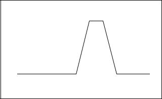
The Unloaded Cycle exercise runs the engine for 20 minutes in the cycle shown in Figure 2-1 and described below.
DRuns at reduced speed for 10 minutes to warm up and exercise the engine.
D Ramps up and runs at full speed for 3 minutes. Engine diagnostics are performed during this full-speed portion of the cycle, which provides the best test of engine and alternator power backup capability. Diagnostic tests at full speed can identify potential problems with the power output and alert the operator before an emergency event.
D Ramps down and runs at reduced speed for 5 minutes to cool down the engine before shutting down automatically.
Speed, RPM |
|
3 min. |
|
|
1 min. |
1 min. |
|
Engine |
10 min. |
|
5 min. |
|
|
||
|
Engine |
Full-Speed |
Cooldown |
|
Exercise |
Diagnostics |
|
Figure 2-1 Unloaded Exercise Cycle
22 Section 2 Generator Set Operation |
TP-6880 10/14 |
System Diagnostics
During the unloaded exercise, the controller monitors the following data. The controller display indicates that the generator set is running, unless a fault is detected as described below.
D ATS connection. The controller verifies that the Model RXT ATS interface board is connected.
DBattery voltage. Battery voltage is checked before exercise to verify engine starting capability. Battery voltage provides a measurement of battery health. If the controller detects low battery voltage, the condition is indicated on the display.
D Communication integrity tests. J1939, RBUS, Ethernet, and USB are monitored for messages indicating that the controller and wiring are reliable.
D Engine speed. Engine speed is measured at reduced speed and full speed. An overspeed or underspeed condition will result in a fault condition and shutdown.
D Generator output frequency and voltage.
Operating the generator at full speed allows the RDC2/DC2 controller to check the output power for correct voltage, frequency, and stability. When the engine is running at full speed, the controller verifies that the voltage and frequency are within acceptable limits. A fault message is displayed if the voltage or frequency is out of range.
D Oil pressure. Oil pressure is verified to ensure proper lubrication of critical engine components. Pressure is monitored at both reduced and full speeds. If the oil pressure is low, the Low Oil Pressure message is displayed and the generator set shuts down.
2.4.3Unloaded Full-Speed Exercise
The unloaded full-speed exercise runs the generator set at full speed for 20 minutes without transferring the load.
To set an unloaded full-speed exercise, follow the procedure in Figure 3-8 and select Exercise Mode: Unloaded Full.
2.4.4Loaded Full-Speed Exercise (with RXT only)
A loaded exercise starts the generator set, ramps up to full speed, and then transfers the electrical load from the utility source to the generator set. After 20 minutes, the load is transferred back to the utility source. The engine runs without load for 5 minutes or until cool, and then shuts down automatically.
Note: With a loaded exercise, power to the building is lost for up to 10 seconds during load transfer.
For a loaded exercise controlled by the RDC2 or DC2 controller, a Model RXT transfer switch must be connected to the generator set. To set a loaded exercise, follow the procedure in Figure 3-8 and select Exercise Type: Loaded.
For a loaded exercise with a transfer switch other than a Kohlerr Model RXT, program the exercise at the transfer switch controller. Refer to the transfer switch operation manual for instructions.
2.4.5Power Failure During Exercise Cycle
If the utility power is lost during an unloaded exercise, the ATS transfers to the emergency source, the exercise is ended and the control remains in the AUTO mode.
If the utility power is lost during a loaded exercise, the exercise is ended. The ATS remains in the emergency position and the control goes into the AUTO mode.
The generator set continues to run and supply power to the load for the duration of the utility power outage. When Utility power is restored, the ATS will re-transfer to the utility source through normal timing sequences.
TP-6880 10/14 |
Section 2 Generator Set Operation 23 |
 Loading...