


 Loading...
Illustrated Parts Manual
Models 10VP 15VP 20VP
3120729
April 29, 2011
REVISION LOG
Note: This manual for use with VP Models built serial number 0130001577 to Present. For machines with serial numbers prior to 0130001577 refer to manual part number 3123001.
September 1997 - Original Issue (Manual edited to Final Assembly 0010548 Rev. 1)
November 1997 - Change 1 (Manual edited to Final Assembly 0010548 Rev. 4)
Pages Effected:
Cover
Effectivity Page a
Section 1 Pages: 1-2 to 1-5, 1-10, 1-11
Section 2 Pages: 3-2, 3-6, 3-10, 3-13
Section 3 Pages: 1-2 to 1-5, 1-10, 1-11
Section 4 Pages: 4-2 to 4-13
Section 6 Pages: 6-3
Section 8 Pages: 8-2 to 8-5
Section 9 Pages: 9-1
Section 10 Pages: 10-1
March 17, 2000 - Revised (Manual edited to Final Assembly 0010548 Rev. 20)
September 12, 2000 - Revised (Manual edited to Final Assembly 0010548 Rev. 25)
March 19, 2003 - Revised (Manual edited to Final Assembly 0010548 Rev. 30)
November 1, 2006 - Revised
April 29, 2011 - Revised
3120729 |
A |
REVISION LOG
B |
3120729 |
TABLE OF CONTENTS
FIGURE NO. |
TITLE |
PAGE NO. |
SECTION 1 - BASE. . . . . . . . . . . . |
. . . . . . . . . . . . . . . . . . . . . . . . . . . . . . . . . . . . . . . . . |
. . .1-1 |
1-1 BASE ASSEMBLY . . . . . . . . . . . . . . . . . . . . . . . . . . . . . . . . . . . . . . . . . . . . . . . . . . . . . .1-2 1-2 REAR DRIVE ASSEMBLY. . . . . . . . . . . . . . . . . . . . . . . . . . . . . . . . . . . . . . . . . . . . . . . . .1-8 1-3 WHEEL DRIVE MOTOR ASSEMBLY . . . . . . . . . . . . . . . . . . . . . . . . . . . . . . . . . . . . . . . .1-12 1-4 JLG POTHOLE PROTECTION INSTALLATION . . . . . . . . . . . . . . . . . . . . . . . . . . . . . . . .1-14
SECTION 2 - CONTROLS . . . . . . . . . . . . . . . . . . . . . . . . . . . . . . . . . . . . . . . . . . . . . . . . . .2-1
2-1 GROUND CONTROL/POWER PACK INSTALLATIONS . . . . . . . . . . . . . . . . . . . . . . . . .2-2 2-2 PLATFORM CONTROLS AND CABLES INSTALLATIONS . . . . . . . . . . . . . . . . . . . . . . .2-6 2-3 BATTERY CHARGER ASSEMBLY . . . . . . . . . . . . . . . . . . . . . . . . . . . . . . . . . . . . . . . . . .2-10 2-4 PUMP/MOTOR/TANK ASSEMBLY. . . . . . . . . . . . . . . . . . . . . . . . . . . . . . . . . . . . . . . . . .2-12 2-5 CONTROL BOX ASSEMBLY . . . . . . . . . . . . . . . . . . . . . . . . . . . . . . . . . . . . . . . . . . . . . .2-14 2-6 OPTION INSTALLATIONS . . . . . . . . . . . . . . . . . . . . . . . . . . . . . . . . . . . . . . . . . . . . . . . .2-16
SECTION 3 - MAST . . . . . . . . . . . . . . . . . . . . . . . . . . . . . . . . . . . . . . . . . . . . . . . . . . . . . . .3-1
3-1 MAST ASSEMBLY - 10VP . . . . . . . . . . . . . . . . . . . . . . . . . . . . . . . . . . . . . . . . . . . . . . . .3-2 3-2 MAST ASSEMBLY - 15VP . . . . . . . . . . . . . . . . . . . . . . . . . . . . . . . . . . . . . . . . . . . . . . . .3-6 3-3 MAST ASSEMBLY - 20VP . . . . . . . . . . . . . . . . . . . . . . . . . . . . . . . . . . . . . . . . . . . . . . . .3-10 3-4 MAST MOUNTED COMPONENTS . . . . . . . . . . . . . . . . . . . . . . . . . . . . . . . . . . . . . . . . .3-14
SECTION 4 - PLATFORM. . . . . . . . . . . . . . . . . . . . . . . . . . . . . . . . . . . . . . . . . . . . . . . . . . .4-1
4-1 MOLDED PLATFORM INSTALLATION (PRIOR TO S/N 02370) . . . . . . . . . . . . . . . . . . .4-2 4-2 MOLDED PLATFORM INSTALLATION (S/N 02370 TO PRESENT) . . . . . . . . . . . . . . . .4-6 4-3 QUICK-CHANGE PLATFORM INSTALLATION WITH SLIDE RAIL ENTRY . . . . . . . . . . .4-10 4-4 QUICK-CHANGE PLATFORM INSTALLATION WITH GULLWING GATE (PRIOR TO
S/N 02256) . . . . . . . . . . . . . . . . . . . . . . . . . . . . . . . . . . . . . . . . . . . . . . . . . . . . . . . . . . .4-12 4-5 QUICK-CHANGE PLATFORM INSTALLATION WITH GULLWING GATE (S/N 02256
TO PRESENT) . . . . . . . . . . . . . . . . . . . . . . . . . . . . . . . . . . . . . . . . . . . . . . . . . . . . . . . . .4-16 4-6 QUICK-CHANGE PLATFORM INSTALLATION WITH EXTENSION (PRIOR TO
S/N 02256) . . . . . . . . . . . . . . . . . . . . . . . . . . . . . . . . . . . . . . . . . . . . . . . . . . . . . . . . . . .4-20 4-7 QUICK-CHANGE PLATFORM INSTALLATION WITH EXTENSION (S/N 02256 TO
PRESENT) . . . . . . . . . . . . . . . . . . . . . . . . . . . . . . . . . . . . . . . . . . . . . . . . . . . . . . . . . . .4-24 4-8 OPTIONAL PLATFORM COMPONENTS INSTALLATION . . . . . . . . . . . . . . . . . . . . . . .4-28
SECTION 5 - CYLINDER . . . . . . . . . . . . . . . . . . . . . . . . . . . . . . . . . . . . . . . . . . . . . . . . . . .5-1
5-1 LIFT CYLINDER ASSEMBLY . . . . . . . . . . . . . . . . . . . . . . . . . . . . . . . . . . . . . . . . . . . . . .5-2
SECTION 6 - HYDRAULICS . . . . . . . . . . . . . . . . . . . . . . . . . . . . . . . . . . . . . . . . . . . . . . . . .6-1
6-1 HYDRAULIC DIAGRAM . . . . . . . . . . . . . . . . . . . . . . . . . . . . . . . . . . . . . . . . . . . . . . . . . .6-2
SECTION 7 - ELECTRICAL . . . . . . . . . . . . . . . . . . . . . . . . . . . . . . . . . . . . . . . . . . . . . . . . .7-1
7-1 |
ELECTRICAL SCHEMATIC (PRIOR TO S/N 01491) . . . . . . . . . . . . . . . . . . . . . . . . . . |
7-2 |
7-2 |
ELECTRICAL SCHEMATIC (S/N 01491 TO PRESENT) . . . . . . . . . . . . . . . . . . . . . . . |
7-3 |
7-3 |
ELECTRICAL SCHEMATIC (UL/EE MACHINES) . . . . . . . . . . . . . . . . . . . . . . . . . . . . . |
7-4 |
7-4 |
HARNESS AND CABLES INSTALLATION (STANDARD MACHINES) . . . . . . . . . . . . . |
7-6 |
7-5 |
HARNESS AND CABLES INSTALLATION (EE MACHINES) (S/N 03094 TO |
|
|
PRESENT) . . . . . . . . . . . . . . . . . . . . . . . . . . . . . . . . . . . . . . . . . . . . . . . . . . . . . . . . . . . |
7-12 |
3120729 |
i |
TABLE OF CONTENTS
FIGURE NO. |
TITLE |
PAGE NO. |
SECTION 8 - DECALS . . . . . . . . . . . . . . . . . . . . . . . . . . . . . . . . . . . . . . . . . . . . . . . . . . |
. . . 8-1 |
|
8-1 |
DECALS INSTALLATION . . . . . . . . . . . . . . . . . . . . . . . . . . . . . . . . . . . . . . . . . . . . . |
. . . . 8-2 |
SECTION 9 - RECOMMENDED SERVICE PARTS STOCK . . . . . . . . . . . . . . . . . . . . . . . . 9-1 SECTION 10 - SPECIAL OPTIONS . . . . . . . . . . . . . . . . . . . . . . . . . . . . . . . . . . . . . . . . . . . 10-1 SECTION 11 - PART NUMBER INDEX . . . . . . . . . . . . . . . . . . . . . . . . . . . . . . . . . . . . . . . . 11-1
ii |
3120729 |
|
|
SECTION 1 BASE |
|
|
|
|
|
|
|
|
S |
|
|
|
|
|
|
|
|
|
|
|
|
|
|
E |
|
|
|
TABLE OF CONTENTS |
|
|
|
|
|
|
|
|
C |
|
|
|
|
|
|
|
|
|
FIGURE |
|
DESCRIPTION |
PAGE |
|
T |
|
|
|
|
|
|||
|
|
|
|
|
I |
|
1-1 |
BASE ASSEMBLY |
|
1-2 |
|
|
|
. . . . . . . . . . . . . . . . . . . . . . . . . . . . . . . . . . . . . . . . . . . . . . . . . . . . |
|
|
|
|||
1-2 |
REAR MOTOR ASSEMBLY . . . . . . . . . . . . . . . . . . . . . . . . . . . . . . . . . . . . . . . . . . . . . . . . . |
. 1-8. . |
|
O |
|
|
1-3 |
WHEEL DRIVE MOTOR ASSEMBLY . . . . . . . . . . . . . . . . . . . . . . . . . . . . . . . . . . . . . . . . . . |
. 1-12. . |
|
|
||
1-4 |
JLG POTHOLE PROTECTION INSTALLATION . . . . . . . . . . . . . . . . . . . . . . . . . . . . . . . . . . |
. 1-14. . |
|
N |
|
|
|
|
|
|
|
1 |
|
|
|
|
|
|
B |
|
|
|
|
|
|
A |
|
|
|
|
|
|
S |
|
|
|
|
|
|
E |
|
|
|
|
|
|
|
|
|
|
|
|
|
|
|
3120729 |
1-1 |
S E C T I O N
1
B A S E
SECTION 1 BASE
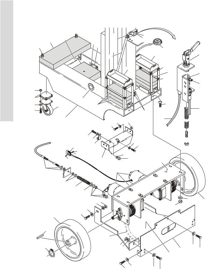
FIGURE 1-1. BASE ASSEMBLY
|
9 |
|
|
|
119 |
|
10 |
31 |
115 |
|
|
9 |
21 |
32 |
103 |
|
120 |
|
121 |
||||
10 |
34 |
33 |
104 |
|
|
35 |
|
30 |
105 |
|
106 |
|
|
|
109 |
|
|
|
|
|
|
22 |
|
|
|
|
102 |
|
|
|
|
|
|
|
|
|
|
|
|
|
11 |
|
|
|
|
2 |
13 |
|
|
|
|
29 |
|
|
|
|
|
|
|
|
|
|
|
|
27 |
|
|
|
|
|
28 |
10 |
|
|
|
|
13 |
|
|
|
|
|
14 |
|
16 |
|
|
|
|
15 |
|
|
|
|
|
|
9 |
5 |
26 |
|
|
|
|
|
|
|
|
|
||
21 |
|
|
|
|
117 |
|
|
|
|
|
|
|
|
|
1 |
|
|
|
104 |
209 |
|
|
104 |
105 |
105 |
||
NOTE: REPLACEMENT DECALS |
|
|||||
103 |
|
116 |
|
|||
MUST BE ORDERED SEPARATELY |
|
|
||||
|
|
118 |
|
|||
|
- SECTION 8. |
111 |
|
|
|
|
|
|
|
|
|
|
|
|
|
112 |
|
|
108 |
|
|
18 |
110 |
|
|
107 |
|
|
37 |
|
112 |
|
|
|
|
|
|
|
|
|
|
|
36 |
|
|
|
|
201 |
|
6 |
|
|
|
|
|
|
6 |
|
|
|
|
|
|
17 |
24 |
|
|
|
|
|
|
|
|
|
|
|
|
|
6 |
|
|
|
|
|
|
910 |
|
|
|
10 |
|
|
9 |
|
|
|
|
|
|
|
|
|
|
|
|
12 |
|
|
|
|
|
|
3 |
|
|
|
|
|
|
23 |
|
|
|
|
|
|
|
|
301 |
|
|
|
|
22 |
|
10 |
9 |
|
|
|
|
|
|
|
|
|
|
|
|
|
|
|
25 |
|
|
|
|
21 |
9 |
9 |
|
|
|
|
|
||
|
|
|
|
|
12 |
|
|
|
|
|
|
|
|
206
202


 204
204
201
208

 203
203


 201
201
9 |
3 |
|
39 |
||
|
9
7 21
1-2 |
3120729 |

SECTION 1 BASE
.
FIGURE 1-1. BASE ASSEMBLY
FIG & ITEM # |
PART NUMBER |
DESCRIPTION |
QTY. |
REV. |
|
|
|
|
|
|
|
BASE ASSEMBLY OPTIONS: |
Ref. |
|
|
0257230 |
10VP (Standard & CSA Machines) |
Ref. |
8 |
|
0257229 |
15VP (Standard Machines) |
Ref. |
8 |
|
0257237 |
15VP (CSA Machines) |
Ref. |
8 |
|
0257228 |
20VP (Standard Machines) |
Ref. |
8 |
|
0257239 |
20VP (CSA Machines) (Prior to S/N 02348) |
Ref. |
4 |
|
0258693 |
20VP (CSA Machines) (S/N 02348 to Present) |
Ref. |
4/B |
1 |
|
Base Weldment Options: |
1 |
|
|
4845561 |
Prior to S/N 02369 |
|
|
|
4845877 |
S/N 02369 to Present |
|
|
2 |
|
Battery Box Weldment Options: |
1 |
|
|
4845258 |
Prior to S/N 02369 |
|
|
|
4845875 |
S/N 02369 to S/N 03094 |
|
|
3 |
4860175 |
Wheel, Rear Assembly |
2 |
|
|
7019659 |
Steel Insert (1 Per Assembly) |
2 |
|
4 |
|
Drive Assembly - Rear (See Figure 1-2 for Breakdown) |
1 |
|
|
|
Options: |
|
|
|
0257241 |
Prior to S/N 02363 |
|
|
|
0258718 |
S/N 02363 to Present |
|
|
5 |
4860177 |
Wheel, Caster Assembly |
2 |
|
|
7019660 |
Axle 1/2” x 3 1/4” (1 Per Assembly) |
2 |
|
|
7019661 |
Wheel, Replacement (1 Per Assembly) |
2 |
|
|
7019662 |
Caster without Wheel (1 Per Assembly) |
2 |
|
|
7019663 |
Bearing, Wheel (1 Per Assembly) |
2 |
|
6 |
1060658 |
Cable, Brake Assembly (See Items for 201-211 |
1 |
|
|
|
Breakdown) |
|
|
7 |
4845474 |
Rear Plate Weldment |
1 |
|
8 |
0630446 |
Bolt 3/8”-16NC x 1” (Carriage) |
4 |
|
9 |
4751600 |
Flatwasher 3/8” Wide |
A/R |
|
10 |
3311605 |
Locknut 3/8”-16NC |
16 |
|
11 |
|
Bolt Options: |
A/R |
|
|
0641406 |
Bolt 1/4”-20NC x 3/4” (Prior to S/N 02369) |
|
|
|
0641508 |
Bolt 5/16”-18NC x 1” (S/N 02369 to S/N 03094) |
|
|
12 |
0641609 |
Bolt 3/8”-16NC x 1 1/8” |
12 |
|
13 |
|
Flatwasher Options: |
A/R |
|
|
4751400 |
Flatwasher 1/4” Wide (Prior to S/N 02369) |
|
|
|
4751500 |
Flatwasher 5/16” Wide (S/N 02369 to S/N 03094) |
|
|
14 |
3539659 |
Plate, Spacer 1/8” |
1 |
|
15 |
3539660 |
Plate, Spacer 5/64” |
1 |
|
16 |
2820086 |
Loom, Wire |
4in/10cm |
|
17 |
4160164 |
Spring, Compression |
2 |
|
18 |
4460648 |
Connector, Terminal |
2 |
|
19 |
3020017 |
Grease, Multi-Purpose (Not Shown) |
A/R |
|
20 |
0100011 |
Compound, Locking (Not Shown) |
A/R |
|
21 |
0641608 |
Bolt 3/8”-16NC x 1” |
5 |
|
|
|
|
|
|
S E C T I O N
1
B A S E
3120729 |
1-3 |

S E C T I O N
1
B A S E
SECTION 1 BASE
FIGURE 1-1. BASE ASSEMBLY (CONTINUED)
FIG & ITEM # |
PART NUMBER |
DESCRIPTION |
QTY. |
REV. |
|
|
|
|
|
22 |
|
Options: |
A/R |
|
|
3760393 |
Ring, Retainer (Prior to S/N 02363) |
2 |
|
|
4845878 |
Battery Box Cover - Right (S/N 02369 to S/N 03094) |
1 |
|
23 |
|
Options: |
A/R |
|
|
2860026 |
Key, Wheel (Prior to S/N 02363) |
2 |
|
|
3311505 |
Locking Nut 5/16”-18NC (S/N 02369 to S/N 03094) |
6 |
|
24 |
|
Options: |
A/R |
|
|
4751000 |
Flatwasher #10 Wide (Prior to S/N 01703) |
2 |
|
|
4740430 |
Flatwasher, Fender (S/N 01703 to Present) |
2 |
|
25 |
3570172 |
Cover, Motor |
1 |
|
26 |
|
Counterweight Weldment Options: |
A/R |
|
|
Not Required |
10VP |
0 |
|
|
4845260 |
15VP (Prior to S/N 02369) |
2 |
|
|
4845879 |
15VP (S/N 02369 to Present) |
2 |
|
|
4845261 |
20VP (Prior to S/N 02369) |
2 |
|
|
4845876 |
20VP (S/N 02369 to Present) |
2 |
|
27 |
0641408 |
Bolt 1/4”-20NC x 1” (Prior to S/N 02369) |
A/R |
|
28 |
3311405 |
Locknut 1/4”-20NC (Prior to S/N 02369) |
A/R |
|
29 |
|
Counterweight Bracket Options: |
A/R |
|
|
Not Required |
10VP & 20VP |
0 |
|
|
0902256 |
15VP (Standard Machines) |
2 |
|
|
0902256 |
15VP (CSA Machines) (Prior to S/N 02369) |
1 |
|
|
Not Required |
15VP (CSA Machines) (S/N 02369 to Present) |
0 |
|
30 |
|
Counterweight Weldment Options: |
A/R |
|
|
Not Required |
10VP & 15VP |
0 |
|
|
4845291 |
20VP |
1 |
|
31 |
0641810 |
Bolt 1/2”-13NC x 1 1/4” |
A/R |
|
32 |
3311805 |
Locknut 1/2”-13NC |
A/R |
|
33 |
4751800 |
Flatwasher 1/2” |
A/R |
|
34 |
|
Counterweight Bracket Options: |
A/R |
|
|
Not Required |
10VP, 15VP & 20VP (Standard Machines) |
0 |
|
|
Not Required |
10VP & 20VP (CSA Machines) |
0 |
|
|
4845401 |
15VP (CSA Machines) |
1 |
|
35 |
0630512 |
Bolt, Carriage |
A/R |
|
36 |
3910620 |
Screw #6-32NC x (S/N 03094 to Present) |
4 |
|
37 |
3310601 |
Nut #6-32NC (S/N 03094 to Present) |
8 |
|
38 |
4750600 |
Flatwasher #6 (S/N 03094 to Present) |
4 |
|
39 |
4711600 |
Flatwasher 3/8” (Standard Machines) (S/N 03609 to |
8 |
|
|
|
Present) |
|
|
|
|
|
|
|
1-4 |
3120729 |
SECTION 1 BASE
FIGURE 1-1. BASE ASSEMBLY (CONTINUED)
FIG & ITEM # |
PART NUMBER |
DESCRIPTION |
QTY. |
REV. |
|
|
|
|
|
|
|
MAST SUPPORT INSTALLATION OPTIONS: |
Ref. |
|
|
0256197 |
STANDARD MACHINES (Prior to S/N 02289) |
Ref. |
4/C |
|
0258582 |
STANDARD MACHINES (S/N 02289 to Present) |
Ref. |
1/A |
|
0256793 |
CSA MACHINES (Prior to S/N 02289) |
Ref. |
3/C |
|
0258583 |
CSA MACHINES (S/N 02289 to Present) |
Ref. |
2/B |
101 |
|
Channel, Lift Cylinder Mounting Options: |
1 |
|
|
4845478 |
Prior to S/N 02289 |
|
|
|
4845804 |
S/N 02289 to Present |
|
|
102 |
|
Brace, Mast Options: |
2 |
|
|
0880124 |
Standard Machines |
|
|
|
0880125 |
CSA Machines |
|
|
103 |
0641609 |
Bolt 3/8”-16NC x 1 1/8” |
A/R |
|
104 |
4751600 |
Flatwasher 3/8” Wide |
24 |
|
105 |
3311605 |
Locknut 3/8”-16NC |
12 |
|
106 |
2420140 |
Gauge, Level |
1 |
|
107 |
0641505 |
Bolt 5/16”-18NC x 5/8” |
1 |
|
108 |
4711500 |
Flatwasher 5/16” Narrow |
1 |
|
109 |
0641612 |
Bolt 3/8”-16NC x 1 1/2” |
1 |
|
110 |
1320041 |
Clamp |
1 |
|
111 |
0641404 |
Bolt 1/4”-20NC x 1/2” |
1 |
|
112 |
4711400 |
Flatwasher 1/4” Narrow |
2 |
|
113 |
3311401 |
Nut 1/4”-20NC |
1 |
|
114 |
0100011 |
Compound, Locking (Not Shown) |
A/R |
|
115 |
|
Shim - .03 Options: |
A/R |
|
|
Not Required |
Standard Machines |
0 |
|
|
4700952 |
CSA Machines |
1 |
|
116 |
|
Shim - .03 Options: |
A/R |
|
|
Not Required |
Standard Machines |
0 |
|
|
4700953 |
CSA Machines |
2 |
|
117 |
0641612 |
Bolt 3/8”-16NC x 1 1/2” |
2 |
|
118 |
|
Shim - .06 Options: |
A/R |
|
|
Not Required |
Standard Machines |
0 |
|
|
4700954 |
CSA Machines |
6 |
|
119 |
|
Plate, Hood Mount Options: |
A/R |
|
|
Not Required |
Standard Machines |
0 |
|
|
3570094 |
CSA Machines |
1 |
|
120 |
|
Flatwasher 1/4” Options: |
A/R |
|
|
Not Required |
Standard Machines |
0 |
|
|
4751400 |
CSA Machines |
1 |
|
121 |
|
Bolt 1/4”-20NC x 3/4” Options: |
A/R |
|
|
Not Required |
Standard Machines |
0 |
|
|
0641406 |
CSA Machines |
1 |
|
|
|
|
|
|
S E C T I O N
1
B A S E
3120729 |
1-5 |
|
|
|
|
|
SECTION 1 BASE |
|
|
|
S |
|
FIGURE 1-1. BASE ASSEMBLY (CONTINUED) |
|
|
||
|
E |
|
|
|
|
|
|
|
C |
|
FIG & ITEM # |
PART NUMBER |
DESCRIPTION |
QTY. |
REV. |
|
|
|
|||||
|
T |
|
|
|
|
|
|
|
|
|
1060658 |
BRAKE CABLE ASSEMBLY |
Ref. |
3/C |
|
|
|
|
|
||||
|
I |
|
201 |
0641528 |
Bolt 5/16”-18NC x 3 1/2” |
1 |
|
|
O |
|
202 |
3311501 |
Nut 5/16”-18NC |
1 |
|
|
|
|
|
||||
|
N |
|
203 |
4160166 |
Spring, Compression |
1 |
|
|
|
204 |
0561284 |
Bar, Aluminum |
1 |
|
|
|
|
|
205 |
3900248 |
Bolt 1/4”-20NC x 1/4” |
2 |
|
|
1 |
|
206 |
2560150 |
Handle, Brake Cable |
1 |
|
|
|
207 |
3570382 |
Bracket, Brake Cable |
1 |
|
|
|
B |
|
208 |
1060661 |
Cable, Brake |
1 |
|
|
|
209 |
1060662 |
Cable, Brake |
1 |
|
|
|
|
|
|
||||
|
A |
|
210 |
0100019 |
Compound, Locking (Not Shown) |
A/R |
|
|
|
211 |
0100035 |
Compound, Locking (Not Shown) |
A/R |
|
|
|
S |
|
|
|
|
|
|
|
E |
|
|
0270352 |
STATIC STRAP INSTALLATION |
Ref. |
1/A |
|
|
|
|
||||
|
|
|
301 |
0641608 |
Bolt 3/8”-16NC x 1” |
1 |
|
|
|
|
|
3311605 |
Locknut 3/8”-16NC |
1 |
|
|
|
|
|
4751600 |
Flatwasher 3/8” |
2 |
|
|
|
|
|
4240084 |
Strap, Static |
1 |
|
|
|
|
|
|
|
|
|
1-6 |
3120729 |
|
|
SECTION 1 BASE |
|
|
|
S |
|
FIGURE 1-1. BASE ASSEMBLY (CONTINUED) |
|
|
|
|
|||
|
|
|
E |
|
|||
|
|
|
|
|
|
|
|
|
|
|
|
|
|
C |
|
FIG & ITEM # |
PART NUMBER |
DESCRIPTION |
QTY. |
REV. |
|
|
|
|
|
|
|||||
|
|
|
|
|
|
T |
|
|
|
|
|
|
|
|
|
|
|
|
|
|
|
I |
|
|
|
|
|
|
|
O |
|
|
|
|
|
|
|
N |
|
|
|
|
|
|
|
1 |
|
|
|
|
|
|
|
B |
|
|
|
|
|
|
|
A |
|
|
|
|
|
|
|
S |
|
|
|
|
|
|
|
E |
|
|
|
|
|
|
|
|
|
|
|
|
|
|
|
|
|
3120729 |
1-7 |

S E C T I O N
1
B A S E
SECTION 1 BASE
FIGURE 1-2. REAR DRIVE ASSEMBLY
1
|
7 |
|
9 |
|
6 |
|
25 |
|
10 |
26 |
24 |
8 |
23 |
|
20 23
5
11A
12
13
11
5
EXPLODED VIEW RIGHT SIDE
DRIVE MOTOR.
 21
21

 19
19
|
104 |
108 |
|
203 |
|
105 |
107 |
109 |
|
210 |
|
205 |
204 |
||||
106 |
|
|
206 |
|
211 |
|
|
|
|
||
103 |
|
|
208 |
|
|
101 |
|
|
201 |
|
|
102 |
|
|
209 |
|
|
|
|
|
207 |
|
202 |
DETAIL |
|
|
|
||
|
DETAIL |
||||
OF ITEM 4 |
OF ITEM 4 |
||||
(PRIOR TO |
(SEPTEMBER 1999 |
||||
SEPTEMBER 1999) |
TO PRESENT) |
||||
22 |
|
|
10 |
|
|
|
|
4 |
|
|
|
21 |
|
|
|
|
|
|
18 |
|
|
|
|
|
17 |
3 |
|
2 |
(NOT SHOWN) |
1-8 |
3120729 |

SECTION 1 BASE
FIGURE 1-2. REAR DRIVE ASSEMBLY
FIG & ITEM # |
PART NUMBER |
DESCRIPTION |
QTY. |
REV. |
|
|
|
|
|
|
|
REAR DRIVE ASSEMBLY OPTIONS: |
Ref. |
|
|
0257241 |
Prior to S/N 02363 |
Ref. |
3/C |
|
0258718 |
S/N 02363 to Present |
Ref. |
1/B |
1 |
4845473 |
Weldment, Drive |
1 |
|
2 |
3570168 |
Plate, Motor Mount (Left) |
1 |
|
3 |
3570169 |
Plate, Motor Mount (Right) |
1 |
|
4 |
1400126 |
Clutch, Torque Limiting Options: |
2 |
|
|
|
Dalton Brand Clutch, Torque Limiting (See Items |
|
|
|
|
101-109 for Breakdown) (Prior to September 1999) |
|
|
|
|
EPT Brand Clutch, Torque Limiting (See Items |
|
|
|
|
201-211 for Breakdown) (September 1999 to |
|
|
|
|
Present) |
|
|
5 |
|
Wheel Drive Motor Assembly (See Figure 1-3 for |
2 |
|
|
|
Breakdown) Options: |
|
|
|
3160217 |
Prior to S/N 02363 |
|
|
|
3160234 |
S/N 02363 to Present |
|
|
6 |
|
Shaft, Drive Options: |
2 |
|
|
4040259 |
Prior to S/N 02363 |
|
|
|
4040268 |
S/N 02363 to Present |
|
|
7 |
2860027 |
Key, Clutch |
2 |
|
8 |
0741609 |
Bolt 3/8”-16NC x 1 1/8” |
2 |
|
9 |
3440520 |
Pin, Roll |
2 |
|
10 |
0440221 |
Bearing, Flange |
4 |
|
11 |
0256851 |
Brake Assembly |
2 |
|
|
7014117 |
Switch, Micro (1 Per Assembly) |
2 |
|
|
7014118 |
Disc, Friction (1 Per Assembly) |
2 |
|
11A |
7014119 |
Gear (1 Per Assembly) |
2 |
|
|
7014120 |
Setscrew (2 Per Assembly) |
4 |
|
12 |
3930808 |
Bolt #8-32NC x 1/2” |
8 |
|
13 |
4750800 |
Flatwasher #8 |
8 |
|
14 |
0100035 |
Compound, Locking (Not Shown) |
A/R |
|
15 |
0100011 |
Compound, Locking (Not Shown) |
A/R |
|
16 |
0100019 |
Compound, Locking (Not Shown) |
A/R |
|
17 |
3900221 |
Bolt 5/16”-18NC x 3/4” |
6 |
|
18 |
0641610 |
Bolt 3/8”-16NC x 1 1/4” |
2 |
|
19 |
0641609 |
Bolt 3/8”-16NC x 1 1/8” |
4 |
|
20 |
0641711 |
Bolt 7/16”-14NC x 1 3/8” |
8 |
|
21 |
4751600 |
Flatwasher 3/8” |
8 |
|
22 |
3311605 |
Locknut 3/8”-16NC |
2 |
|
23 |
4711700 |
Flatwasher 7/16” |
16 |
|
24 |
3311705 |
Locknut 7/16”-14NC |
8 |
|
25 |
2860029 |
Key, Wheel |
2 |
|
26 |
4740478 |
Washer, Wheel Retainer |
2 |
|
|
|
|
|
|
S E C T I O N
1
B A S E
3120729 |
1-9 |

S E C T I O N
1
B A S E
SECTION 1 BASE
FIGURE 1-2. REAR DRIVE ASSEMBLY (CONTINUED)
FIG & ITEM # |
PART NUMBER |
DESCRIPTION |
QTY. |
REV. |
|
|
|
|
|
|
1400126 |
TORQUE LIMITER CLUTCH ASSEMBLY (DALTON |
Ref. |
A |
|
|
BRAND) (PRIOR TO SEPTEMBER 1999) |
|
|
101 |
7016689 |
Hub |
1 |
|
102 |
7016683 |
Nut, Adjusting |
1 |
|
103 |
7016684 |
Spring |
1 |
|
104 |
7016685 |
Bearing |
1 |
|
105 |
7016691 |
Facing, Friction |
2 |
|
106 |
7016690 |
Plate, Pressure |
1 |
|
107 |
7016686 |
Sprocket |
1 |
|
108 |
7016687 |
Coupling, Chain |
1 |
|
109 |
7016688 |
Sprocket |
1 |
|
|
1400126 |
TORQUE LIMITER CLUTCH ASSEMBLY (EPT |
Ref. |
C |
|
|
BRAND) (SEPTEMBER 1999 TO PRESENT) |
|
|
201 |
7023351 |
Hub |
1 |
|
202 |
7023352 |
Chain |
1 |
|
203 |
7023353 |
Sprocket |
1 |
|
204 |
7023354 |
Bushing |
1 |
|
205 |
7023355 |
Facing, Friction |
2 |
|
206 |
7023356 |
Plate, Pressure |
1 |
|
207 |
7023357 |
Disc, Spring |
3 |
|
208 |
7023358 |
Lockwasher, Tabbed |
1 |
|
209 |
7023359 |
Nut, Adjusting |
1 |
|
210 |
7023360 |
Sprocket |
1 |
|
211 |
7023361 |
Setscrew |
1 |
|
|
|
|
|
|
1-10 |
3120729 |
|
|
SECTION 1 BASE |
|
|
|
S |
|
FIGURE 1-2. REAR DRIVE ASSEMBLY (CONTINUED) |
|
|
|
|
|||
|
|
|
E |
|
|||
|
|
|
|
|
|
|
|
|
|
|
|
|
|
C |
|
FIG & ITEM # |
PART NUMBER |
DESCRIPTION |
QTY. |
REV. |
|
|
|
|
|
|
|||||
|
|
|
|
|
|
T |
|
|
|
|
|
|
|
|
|
|
|
|
|
|
|
I |
|
|
|
|
|
|
|
O |
|
|
|
|
|
|
|
N |
|
|
|
|
|
|
|
1 |
|
|
|
|
|
|
|
B |
|
|
|
|
|
|
|
A |
|
|
|
|
|
|
|
S |
|
|
|
|
|
|
|
E |
|
|
|
|
|
|
|
|
|
|
|
|
|
|
|
|
|
3120729 |
1-11 |
|
SECTION 1 BASE |
S |
FIGURE 1-3. WHEEL DRIVE MOTOR ASSEMBLY |
E |
|
C |
|
T |
|
I |
|
O |
|
N |
|
1 |
|
B |
|
A |
|
S |
|
E |
|
|
|
1-12 |
3120729 |

SECTION 1 BASE
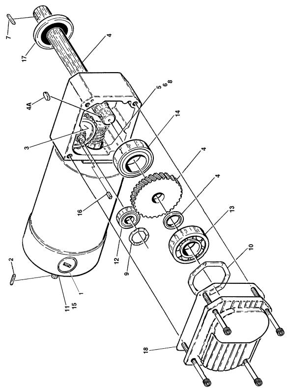
FIGURE 1-3. WHEEL DRIVE MOTOR ASSEMBLY
FIG & ITEM # |
PART NUMBER |
DESCRIPTION |
QTY. |
REV. |
|
|
|
|
|
|
|
DRIVE MOTOR ASSEMBLY OPTIONS: |
Ref. |
|
|
3160217 |
Prior to S/N 02363 |
Ref. |
D |
|
3160234 |
S/N 02363 to Present |
Ref. |
C |
1 |
7018000 |
Brush Kit |
1 |
|
|
7018044 |
Holder, Brush |
1 |
|
2 |
7018001 |
Key, Shaft |
1 |
|
3 |
7018002 |
Gear and Pinion Assembly |
1 |
|
4 |
7018019 |
Gear and Drive Shaft |
1 |
|
4A |
7018007 |
Key, Shaft |
1 |
|
5 |
7018018 |
Seal, Lip |
1 |
|
6 |
7018005 |
Ring, Retaining |
1 |
|
7 |
2860028 |
Shaft, Key |
1 |
|
8 |
7018008 |
Bearing |
2 |
|
9 |
7018009 |
Washer, Wave |
1 |
|
10 |
7018010 |
Washer, Wave |
1 |
|
11 |
7018011 |
Washer, Wave |
1 |
|
12 |
7018012 |
Bearing 32mm x 12mm x 10mm |
2 |
|
13 |
7018013 |
Bearing 47mm x 20mm x 14mm |
1 |
|
14 |
7018014 |
Bearing 47mm x 25mm x 12mm |
1 |
|
15 |
7018027 |
Bearing |
1 |
|
16 |
7018015 |
Shaft, Key |
1 |
|
17 |
7018026 |
Seal, Lip |
1 |
|
18 |
|
O-Ring Options: |
1 |
|
|
Not Required |
Prior to S/N 02363 |
|
|
|
7018028 |
S/N 02363 to Present |
|
|
|
|
|
|
|
S E C T I O N
1
B A S E
3120729 |
1-13 |
S E C T I O N
1
B A S E
SECTION 1 BASE
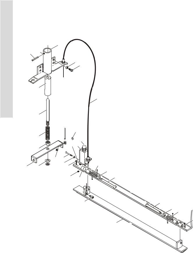
FIGURE 1-4. JLG POTHOLE PROTECTION INSTALLATION
13
2
5
3
11
612


11
1
14


 29 26
29 26 
15 23 9
24 


 25
25 


25 18
14
7
19
22
21
FRAME REF.
20
22
19
24
16 (LEFT SIDE)
17 (RIGHT SIDE)
1-14 |
3120729 |
SECTION 1 BASE
FIGURE 1-4. JLG POTHOLE PROTECTION INSTALLATION
FIG & ITEM # |
PART NUMBER |
DESCRIPTION |
QTY. |
REV. |
|
|
|
|
|
|
0257490 |
JLG POTHOLE PROTECTION INSTALLATION |
Ref. |
2/B |
1 |
4845507 |
Actuator Weldment |
1 |
|
2 |
4567203 |
Tube, Sleeve |
1 |
|
3 |
4160160 |
Spring, Compression |
1 |
|
4 |
3020022 |
Grease, Lithium (with PTFE) (Not Shown) |
A/R |
|
5 |
3841343 |
Rod, Actuator |
1 |
|
6 |
3570230 |
Plate, Cable Attach |
1 |
|
7 |
1060649 |
Cable |
2 |
|
8 |
0641405 |
Bolt 1/4”-20NC x 5/8” |
4 |
|
9 |
4750600 |
Flatwasher #6 |
4 |
|
10 |
4711400 |
Flatwasher 1/4” Narrow |
4 |
|
11 |
3312002 |
Nut, Jam 5/8”-11NC |
2 |
|
12 |
4712000 |
Flatwasher 5/8” Narrow |
1 |
|
13 |
3440418 |
Rollpin 1/8” 1 1/8” |
1 |
|
14 |
3900202 |
Screw, Shoulder 1/4”-20NC x 1/4” |
4 |
|
15 |
3311005 |
Locknut #10-24NC |
2 |
|
16 |
4845508 |
Bar, Pothole (Left Side) |
1 |
|
17 |
4845509 |
Bar, Pothole (Right Side) |
1 |
|
18 |
1100103 |
Cam |
2 |
|
19 |
4160162 |
Spring, Torsion |
4 |
|
20 |
3430630 |
Pin, Clevis 3/8” x 3 3/4” |
2 |
|
21 |
3430638 |
Pin, Clevis 3/8” x 4 3/4” |
2 |
|
22 |
4751600 |
Flatwasher 3/8” |
4 |
|
23 |
3910620 |
Screw #6-32NC x 1 1/4” |
4 |
|
24 |
3450403 |
Pin, Cotter 1/8” x 3/4” |
4 |
|
25 |
3900249 |
Setscrew #10-32NC x 3/16” |
4 |
|
26 |
4360456 |
Switch, Limit |
2 |
|
27 |
0100035 |
Compound, Locking (Not Shown) |
A/R |
|
28 |
0100011 |
Compound, Locking (Not Shown) |
A/R |
|
29 |
4460662 |
Connector, Strain Relief |
2 |
|
|
|
|
|
|
S E C T I O N
1
B A S E
3120729 |
1-15 |
|
|
|
|
|
SECTION 1 BASE |
|
|
|
S |
|
FIGURE 1-4. JLG POTHOLE PROTECTION INSTALLATION (CONTINUED) |
|
|
||
|
E |
|
|
|
|
|
|
|
C |
|
FIG & ITEM # |
PART NUMBER |
DESCRIPTION |
QTY. |
REV. |
|
|
|
|||||
|
T |
|
|
|
|
|
|
|
|
|
|
|
|
|
|
|
I |
|
|
|
|
|
|
|
O |
|
|
|
|
|
|
|
N |
|
|
|
|
|
|
|
1 |
|
|
|
|
|
|
|
B |
|
|
|
|
|
|
|
A |
|
|
|
|
|
|
|
S |
|
|
|
|
|
|
|
E |
|
|
|
|
|
|
|
|
|
|
|
|
|
|
|
|
|
|
|
|
|
|
1-16 |
3120729 |

SECTION 2 CONTROLS
TABLE OF CONTENTS
FIGURE |
DESCRIPTION |
PAGE |
|
|
|
2-1 GROUND CONTROL/POWER PACK INSTALLATIONS. . . . . . . . . . . . . . . . . . . . . . . . . . . . . . . 2-2 2-2 PLATFORM CONTROLS AND CABLES INSTALLATIONS . . . . . . . . . . . . . . . . . . . . . . . . . . . . 2-6 2-3 BATTERY CHARGER ASSEMBLIES . . . . . . . . . . . . . . . . . . . . . . . . . . . . . . . . . . . . . . . . . . . . . 2-10 2-4 PUMP/MOTOR/TANK ASSEMBLY . . . . . . . . . . . . . . . . . . . . . . . . . . . . . . . . . . . . . . . . . . . . . . . 2-12 2-5 CONTROL BOX ASSEMBLY . . . . . . . . . . . . . . . . . . . . . . . . . . . . . . . . . . . . . . . . . . . . . . . . . . . 2-14 2-6 OPTION INSTALLATIONS . . . . . . . . . . . . . . . . . . . . . . . . . . . . . . . . . . . . . . . . . . . . . . . . . . . . . 2-16
S E C T I O N
2
C O N T R O L S
3120729 |
2-1 |
SECTION 2 CONTROLS
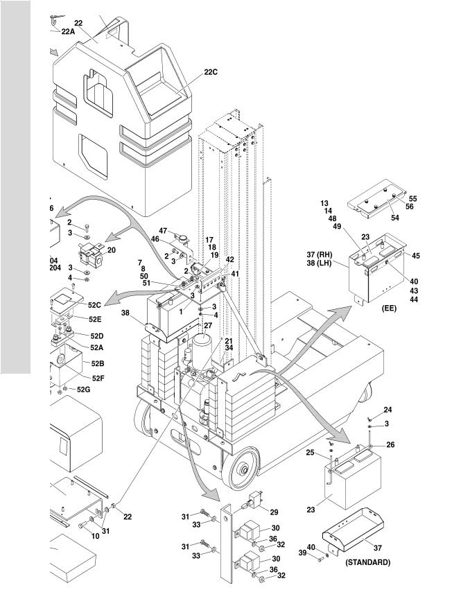
FIGURE 2-1. GROUND CONTROL/POWER PACK INSTALLATIONS
S
E
C
T
I
O
N
2
C
O
N
T
R
O
L
S
2-2 |
3120729 |

SECTION 2 CONTROLS
.
FIGURE 2-1. GROUND CONTROL/POWER PACK INSTALLATIONS
FIG & ITEM # |
PART NUMBER |
DESCRIPTION |
QTY. |
REV. |
|
|
|
|
|
|
|
GROUND CONTROL/POWER PACK INSTALLATIONS |
Ref. |
|
|
0256143 |
Machines With Wet Batteries |
Ref. |
15 |
|
0258008 |
Machines With Dry Batteries |
Ref. |
7 |
|
0256928 |
CSA Spec Machines (Additional Components) |
Ref. |
|
|
0270167 |
(EE) Spec Machines (S/N 03094 to Present) |
Ref. |
5 |
1 |
|
Bracket, Ground Controls Options: |
1 |
|
|
0902248 |
(Standard) (Prior to S/N 03094) |
|
|
|
0902643 |
(Standard) (S/N 03094 to Present) |
|
|
|
0902649 |
(EE) (S/N 03094 to Present) |
|
|
|
3570094 |
Plate, Hood Mounting (CSA Only) (Not Shown - Located on |
1 |
|
|
|
Top of Item #1) |
|
|
2 |
0641406 |
Bolt 1/4”-20NC x 3/4” |
9 |
|
3 |
4751400 |
Flatwasher 1/4” Wide |
19 |
|
4 |
3311405 |
Locknut 1/4”-20NC |
2 |
|
5 |
|
Ground Control Assembly (See Items 101-105 For |
1 |
|
|
|
Breakdown) Options: |
|
|
|
0861039 |
Prior to S/N 02862 |
|
|
|
0861291 |
S/N 02862 to S/N 03094 |
|
|
|
0861355 |
S/N 03094 to S/N 03905 |
|
|
|
0861291 |
S/N 03905 to Present |
|
|
6 |
|
Screw, Machine Options: |
4 |
|
|
3910812 |
Prior to S/N 03094 - #8-32NC x 3/4” |
|
|
|
0721006 |
S/N 03094 to Present - #10-24NC x 3/4” |
|
|
7 |
|
Flatwasher Options: |
A/R |
|
|
4750800 |
Prior to S/N 03094 - Flatwasher #8 |
|
|
|
4751000 |
S/N 03094 to Present - Flatwasher #10 |
|
|
8 |
|
Locknut Options: |
A/R |
|
|
3310805 |
Locknut #8-32NC (Prior to S/N 02315) |
|
|
|
3300392 |
Locknut #8-32NC (Brass) (S/N 02315 to S/N 03094) |
|
|
|
3311005 |
Locknut #10-24NC (S/N 03094 to Present) |
|
|
9 |
Not Used |
|
|
|
10 |
0741407 |
Screw, Flathead 1/4”-20NC x 7/8” |
4 |
|
11 |
0181857 |
Angle, Controller Mount |
1 |
|
12 |
3311601 |
Nut 3/8”-16NC (EE Machines Only) |
2 |
|
13 |
3311501 |
Nut 5/16”-18NC (EE Machines Only) |
2 |
|
14 |
0100011 |
Compound, Locking (Not Shown) |
A/R |
|
15 |
1600238 |
Controller Assembly (Prior to S/N 02996) |
1 |
|
|
2900868 |
Controller Configuration Kit |
1 |
|
|
1600305 |
Controller Assembly (S/N 02996 to Present) |
1 |
|
|
2900868 |
Controller Configuration Kit |
1 |
|
16 |
0902250 |
Bracket, Battery Charger |
1 |
|
17 |
0641608 |
Bolt 3/8”-16NC x 1” |
10 |
|
18 |
4751600 |
Flatwasher 3/8” |
20 |
|
19 |
3311605 |
Locknut 3/8”-16NC |
10 |
|
20 |
|
Relay, 100Amp Options: |
1 |
|
|
3740120 |
Prior to S/N 02315 |
|
|
|
3740130 |
S/N 02315 to Present |
|
|
|
|
|
|
|
S E C T I O N
2
C O N T R O L S
3120729 |
2-3 |

S E C T I O N
2
C O N T R O L S
SECTION 2 CONTROLS
FIGURE 2-1. GROUND CONTROL/POWER PACK INSTALLATIONS
FIG & ITEM # |
PART NUMBER |
DESCRIPTION |
QTY. |
REV. |
|
|
|
|
|
21 |
3539565 |
Plate, Pump Mounting |
1 |
|
22 |
2680432 |
Hood |
1 |
|
22A |
2700080 |
Hook |
2 |
|
22B |
7023342 |
Lid |
1 |
|
22C |
7023341 |
Lid |
1 |
|
23 |
0400122 |
Battery (Wet) |
2 |
|
|
0400144 |
Battery (Dry) |
2 |
|
24 |
3300202 |
Wingnut (Not Required On (EE) Machines) |
4 |
|
25 |
0630504 |
Bolt, Battery Hold Down (Not Required On (EE) Machines) |
4 |
|
26 |
0362658 |
Bar, Battery Hold Down (Not Required On (EE) Machines) |
2 |
|
27 |
Not Used |
|
|
|
28 |
4845266 |
Bracket, Brake Release (Prior to S/N 01577) |
1 |
|
29 |
4360314 |
Switch, Ground |
1 |
|
30 |
3740069 |
Relay, Power 24VDC |
2 |
|
31 |
3911010 |
Screw |
2 |
|
32 |
3311001 |
Nut #10-24NC |
2 |
|
33 |
4751000 |
Flatwasher #10 Wide |
4 |
|
34 |
0741605 |
Screw, Countersunk 3/8”-16NC x 5/8” |
2 |
|
35 |
0100051 |
Grease Battery (Not Shown) |
A/R |
|
36 |
4761000 |
Lockwasher #10 |
2 |
|
37 |
|
Battery Box - Right Options: |
1 |
|
|
4845875 |
Standard Machines (S/N 03094 to Present) |
|
|
|
0270299 |
(EE) Machines (S/N 03094 to Present) |
|
|
|
3572654 |
(EE) Machines (Battery Box Lid) |
|
|
38 |
|
Battery Box - Left Options: |
1 |
|
|
4845878 |
Standard Machines (S/N 03094 to Present) |
|
|
|
0270298 |
(EE) Machines (S/N 03094 to Present) |
|
|
|
3572653 |
(EE) Machines (Battery Box Lid) |
|
|
39 |
0641508 |
Bolt 5/16-18NC x 1” |
6 |
|
40 |
4751500 |
Flatwasher 5/16” |
6 |
|
41 |
3380453 |
Panel, Breaker (EE Machines Only) |
1 |
|
42 |
1704584 |
Decal - Breaker Panel (EE Machines Only) |
1 |
|
43 |
0641512 |
Bolt 5/16”-18NC x 1 1/2” |
2 |
|
44 |
3311505 |
Locknut 5/16”-18NC |
2 |
|
45 |
4568103 |
Bar, Battery Hold Down (EE Machines Only) |
2 |
|
46 |
0902657 |
Bracket, Battery Disconnect (EE Machines Only) |
1 |
|
47 |
4360256 |
Switch, Master Disconnect (EE Machines Only) |
1 |
|
48 |
4761500 |
Lockwasher 5/16” |
2 |
|
49 |
4761600 |
Lockwasher 3/8” |
2 |
|
50 |
2400044 |
Fuse Mounting Block (EE Machines Only) (Prior to S/N |
1 |
|
|
|
03682) |
|
|
51 |
0741008 |
Flathead Screw #10-24NC x 1” (EE Machines Only) (Prior |
2 |
|
|
|
to S/N 03682) |
|
|
52 |
0861381 |
Fuse Box Assembly (EE Machines Only) (S/N 03682 to |
1 |
B |
|
|
Present) |
|
|
52A |
0741006 |
Screw #10-24NC x 3/4” |
2 |
|
52B |
0861380 |
Box, Fuse (EE) |
1 |
|
52C |
1704713 |
Decal - Fuse |
1 |
|
52D |
2400044 |
Fuse Mounting Block |
1 |
|
|
|
|
|
|
2-4 |
3120729 |

SECTION 2 CONTROLS
FIGURE 2-1. GROUND CONTROL/POWER PACK INSTALLATIONS
FIG & ITEM # |
PART NUMBER |
DESCRIPTION |
QTY. |
REV. |
|
|
|
|
|
52E |
2400045 |
Fuse, 80Amp |
1 |
|
52F |
2540040 |
Grommet, Rubber |
2 |
|
52G |
3311005 |
Locknut #10-24NC |
2 |
|
53 |
0641408 |
Bolt 1/4”-20NC x 1” (EE Machines Only) (S/N 03682 to |
2 |
|
|
|
Present) |
|
|
54 |
3572651 |
Plate, Battery Access (EE Machines Only) (S/N 03682 to |
2 |
|
|
|
Present) |
|
|
55 |
1380138 |
Clip, Receptial (EE Machines Only) (S/N 03682 to Present) |
8 |
|
56 |
3900174 |
Screw (EE Machines Only) (S/N 03682 to Present) |
8 |
|
57 |
0962346 |
Bushing, Spacer (EE Machines Only) (S/N 03682 to |
2 |
|
|
|
Present) |
|
|
58 |
1704679 |
Decal - Battery Disconnect (EE Machines Only) (S/N 03887 |
|
|
|
|
to Present) |
|
|
59 |
3820006 |
Pop Rivet (EE Machines Only) (S/N 03887 to Present) |
4 |
|
|
0861039 |
GROUND CONTROL ASSEMBLY (PRIOR TO S/N 02862) |
Ref. |
A |
101 |
7017701 |
Switch, Push-Turn to Reset (Emergency Stop) |
1 |
|
|
7017703 |
Block, Contact - N.C. |
2 |
|
|
7017715 |
Button - Red |
1 |
|
102 |
7017700 |
Switch - Key (Lift) |
1 |
|
|
7017702 |
Block, Contact - N.C. |
2 |
|
102A |
7017704 |
Key, Replacement |
1 set |
|
103 |
|
Strain Relief Connector Options: |
1 |
|
|
7012637 |
Connector, Strain Relief (CG16) |
|
|
|
7017713 |
Connector, Strain Relief (CG20) |
|
|
104 |
7017706 |
Nameplate - Emergency Stop |
1 |
|
105 |
7017705 |
Nameplate - Select |
1 |
|
|
0861291 |
GROUND CONTROL ASSEMBLY (S/N 02862 TO S/N 03094) |
Ref. |
A |
|
0861355 |
GROUND CONTROL ASSEMBLY (S/N 03094 TO S/N 03905) |
Ref. |
A |
|
0861291 |
GROUND CONTROL ASSEMBLY (S/N 03905 TO PRESENT) |
Ref. |
A |
201 |
7020078 |
Switch, Push-Turn to Reset (Emergency Stop) |
1 |
|
202 |
4360471 |
Switch - Key (Lift) |
1 |
|
202A |
7020174 |
Key, Replacement |
1 set |
|
203 |
4460633 |
Strain Relief Connector |
1 |
|
204 |
7020096 |
Nameplate - Emergency Stop |
1 |
|
205 |
7020267 |
Nameplate - Select |
1 |
|
|
|
|
|
|
S E C T I O N
2
C O N T R O L S
3120729 |
2-5 |

SECTION 2 CONTROLS
FIGURE 2-2. PLATFORM CONTROLS AND CABLES INSTALLATIONS
S
E
C
T
I
O
N
2
C
O
N
T
R
O
L
S
2-6 |
3120729 |

SECTION 2 CONTROLS
.
FIGURE 2-2. PLATFORM CONTROLS AND CABLES INSTALLATIONS
FIG & ITEM # |
PART NUMBER |
DESCRIPTION |
QTY. |
REV. |
|
|
|
|
|
|
|
PLATFORM CONTROLS AND CABLES INSTALLATIONS |
Ref. |
|
|
0257619 |
10 VP (Standard) |
Ref. |
9 |
|
0270166 |
10 VP (EE) |
Ref. |
2 |
|
0257618 |
15 VP (Standard) |
Ref. |
9 |
|
0270168 |
15 VP (EE) |
Ref. |
2 |
|
0257617 |
20 VP (Standard) |
Ref. |
10 |
|
0270169 |
20 VP (EE) |
Ref. |
2 |
|
|
Note: For Platform Controls & Cables (Restricted Height) |
|
|
|
|
(See Section 10) |
|
|
1 |
3570680* |
Plate, Control Mounting |
1 |
|
1A |
|
Pad, Rubber Options: |
A/R |
|
|
7020075 |
RH Side Pad |
2 |
|
|
7020076 |
LH Side Pad |
2 |
|
2 |
Not Used |
|
|
|
3 |
|
Platform Console Box Assembly Options (See Figure 2-5 |
1 |
|
|
|
For Breakdown): |
|
|
|
1600267 |
Console Box Assembly (Prior to S/N 02996) |
|
|
|
1600304 |
Console Box Assembly (S/N 02996 to Present) |
|
|
4 |
1060564 |
Cable, Electrical |
A/R |
|
|
|
10 VP |
13.5ft/4m |
|
|
|
15 VP |
19ft/5.8m |
|
|
|
20 VP |
23ft/7m |
|
5 |
|
Platform Harness Assembly Options: (See Section 7 for |
1 |
|
|
|
Breakdown) |
|
|
|
4922027 |
10 VP (Prior to S/N 02445) |
|
|
|
4922201 |
10 VP(S/N 02445 to Present) |
|
|
|
4922028 |
15 VP (Prior to S/N 02445) |
|
|
|
4922202 |
15 VP(S/N 02445 to Present) |
|
|
|
4922029 |
20 VP (Prior to S/N 02445) |
|
|
|
4922203 |
20 VP(S/N 02445 to Present) |
|
|
6 |
3422657* |
Pin, Quick Release |
1 |
|
7 |
1060380* |
Cable, Lanyard |
2 |
|
8 |
1320043* |
Clamp, Cable |
1 |
|
9 |
3310801* |
Nut #8-32NC |
A/R |
|
10 |
4750800* |
Flatwasher #8 Wide |
A/R |
|
11 |
3300416* |
Nut, Acorn #8-32NC |
4 |
|
12 |
0100035 |
Compound, Locking (Not Shown) |
A/R |
|
13 |
4160130 |
Spring, Extension |
1 |
|
14 |
3311605 |
Locknut 3/8”-16NC |
1 |
|
15 |
1320149 |
Clamp |
3 |
|
16 |
0641412 |
Bolt 1/4”-20NC x 1 1/2” |
3 |
|
17 |
0100019 |
Compound, Locking (Not Shown) |
A/R |
|
18 |
3311405 |
Locknut 1/4”-20NC |
7 |
|
19 |
3580231 |
Pulley, Sheave |
A/R |
|
20 |
3900200 |
Screw, Shoulder 5/16”-18NC x 1 1/4” |
A/R |
|
21 |
4751500 |
Flatwasher 5/16” Wide |
A/R |
|
22 |
0641406 |
Bolt 1/4”-20NC x 3/4” |
4 |
|
23 |
4711400 |
Flatwasher 1/4” Narrow |
A/R |
|
|
|
|
|
|
S E C T I O N
2
C O N T R O L S
3120729 |
2-7 |

S E C T I O N
2
C O N T R O L S
SECTION 2 CONTROLS
FIGURE 2-2. PLATFORM CONTROLS AND CABLES INSTALLATIONS (CONTINUED)
FIG & ITEM # |
PART NUMBER |
DESCRIPTION |
QTY. |
REV. |
|
|
|
|
|
24 |
4460566 |
Connector, Strain Relief - 90° |
1 |
|
25 |
3380441 |
Panel, Control |
1 |
|
26 |
0860946 |
Box, Electrical |
1 |
|
27 |
|
Receptacle, Electrical Options: |
1 |
|
|
4460190 |
Standard Machines |
|
|
|
4460347 |
(EE) Machines |
|
|
28 |
4060092 |
Cover, Weatherproof |
1 |
|
29 |
0721005 |
Screw, Machine #10-24NC x 5/8” |
2 |
|
30 |
4761000 |
Lockwasher #10 |
2 |
|
31 |
3311001 |
Nut #10-24NC |
2 |
|
32 |
4460023 |
Connector, Strain Relief |
1 |
|
33 |
|
Clamp, Cable Options: |
A/R |
|
|
1320227 |
Prior to S/N 01966 |
7 |
|
|
1320043 |
S/N 01966 to Present |
4 |
|
34 |
|
Hardware Options: |
A/R |
|
|
1020008 |
Button, Nylon (Prior to S/N 01966) |
7 |
|
|
1380132 |
Clip, Gripper (S/N 01966 to Present) |
4 |
|
35 |
4460549 |
Plug, Electrical |
1 |
|
36 |
0960407 |
Bushing (Prior to S/N 02535) |
1 |
|
37 |
4751000 |
Flatwasher #10 Wide |
A/R |
|
38 |
3300047 |
Nut, Conduit |
1 |
|
39 |
|
Carrier Options: |
A/R |
|
|
Not Required |
10VP & 20VP |
0 |
|
|
1180344 |
15VP |
1 |
|
40 |
|
Plate, Spacer Options: |
A/R |
|
|
Not Required |
10VP & 20VP |
0 |
|
|
3539617 |
15VP |
2 |
|
41 |
0641409 |
Bolt 1/4”-20NC x 1” |
A/R |
|
42 |
0641416 |
Bolt 1/4”-20NC x 2” |
A/R |
|
43 |
0641414 |
Bolt 1/4”-20NC x 1 3/4” |
A/R |
|
44 |
3760170 |
Ring, Split |
1 |
|
45 |
0100048 |
Compound, Silicone #661 (Not Shown) |
A/R |
|
46 |
3570737 |
Bracket, Protector |
1 |
|
47 |
|
Hardware Options: |
4 |
|
|
4750800 |
Flatwasher #8 Wide (Prior to S/N 02535) |
|
|
|
3820024 |
Pop Rivet (S/N 02535 to Present) |
|
|
48 |
4760800 |
Lockwasher #8 (Prior to S/N 02535) |
4 |
|
49 |
3310801 |
Nut #8-32NC (Prior to S/N 02535) |
4 |
|
50 |
3910806 |
Screw #8-32NC x 3/8” (Prior to S/N 02535) |
4 |
|
51 |
4740120 |
Washer, Nylon (S/N 03629 to Present) |
4 |
|
|
2901542 |
Controller Mounting Kit (Includes Items with * asterisk) |
1 |
|
|
|
|
|
|
2-8 |
3120729 |
Loading...