


OPERATORS & SAFETY
Models 10VP 15VP 20VP
3120727
April 20, 2000
AUSTRALIAN OFFICE |
EUROPEAN OFFICE |
CORPORATE OFFICE |
JLG INDUSTRIES, INC. |
JLG INDUSTRIES (EUROPE) |
JLG INDUSTRIES, INC. |
P.O. Box 5119 |
Kilmarting Place, |
1 JLG Drive |
11 Bolwarra Road |
Tannochside Park |
McConnellsburg, PA. |
Port Macquarie, Australia |
Uddingston, Scotland, G71 5PH |
17233-9533 |
Telephone: 065 811111 |
Telephone: 01698 811005 |
USA |
Fax: 065 810122 |
Main Fax: 01698 811055 |
Telephone: (717) 485-5161 |
|
Parts Fax: 01698 811455 |
Fax: (717) 485-6417 |
– JLG Lift –

FOREWORD
The purpose of this manual is to provide users with the operating procedures essential for the promotion of proper machine operation for its intended purpose. It is important to over-stress proper machine usage. All information in this manual should be READ and UNDERSTOOD before any attempt is made to operate the machine. YOUR OPERATING MANUAL IS YOUR MOST IMPORTANT TOOL - Keep it with the machine.
REMEMBER ANY EQUIPMENT IS ONLY AS SAFE AS THE OPERATOR.
BECAUSE THE MANUFACTURER HAS NO DIRECT CONTROL OVER MACHINE APPLICATION AND OPERATION, PROPER SAFETY PRACTICES ARE THE RESPONSIBILITY OF THE USER AND HIS OPERATING PERSONNEL.
ALL INSTRUCTIONS IN THIS MANUAL ARE BASED ON THE USE OF THE MACHINE UNDER PROPER OPERATING CONDITIONS, WITH NO DEVIATIONS FROM THE ORIGINAL DESIGN. ALTERATION AND/ OR MODIFICATION OF THE MACHINE IS STRICTLY FORBIDDEN, WITHOUT WRITTEN APPROVAL FROM JLG INDUSTRIES, PER OSHA REGULATIONS.
THIS "SAFETY ALERT SYMBOL" IS USED TO CALL ATTENTION TO POTENTIAL HAZARDS WHICH MAY LEAD TO SERIOUS INJURY OR DEATH IF IGNORED.
Safety of personnel and proper use of the machine are of primary concern, DANGER, WARNING, CAUTION, IMPORTANT, INSTRUCTIONS and NOTE are inserted throughout this manual to emphasize these areas. They are defined as follows:
DANGER INDICATES AN IMMINENTLY HAZARDOUS SITUATION WHICH, IF NOT AVOIDED WILL RESULT IN SERIOUS INJURY OR DEATH.
CAUTION INDICATES A POTENTIALLY HAZARDOUS SITUATION WHICH, IF NOT AVOIDED, MAY RESULT IN MINOR OR MODERATE INJURY. IT MAY ALSO BE USED TO ALERT AGAINST UNSAFE PRACTICES.
WARNING INDICATES A POTENTIALLY HAZARDOUS SITUATION WHICH, IF NOT AVOIDED COULD RESULT IN SERIOUS INJURY OR DEATH.
IMPORTANT OR INSTRUCTIONS PROCEDURES ESSENTIAL FOR SAFE OPERATION AND WHICH, IF NOT FOLLOWED MAY RESULT IN A MALFUNCTION OR DAMAGE TO THE MACHINE.
Also in this Manual "Notes:" are used to provide information of special interest.
JLG INDUSTRIES, INC. MAY HAVE ISSUED SAFETY RELATED BULLETINS FOR YOUR JLG PRODUCT. CONTACT JLG INDUSTRIES, INC. OR THE LOCAL AUTHORIZED JLG DISTRIBUTOR FOR INFORMATION CONCERNING SAFETY RELATED BULLETINS WHICH MAY HAVE BEEN ISSUED FOR YOUR JLG PRODUCT. ALL ITEMS REQUIRED BY THE SAFETY RELATED BULLETINS MUST BE COMPLETED ON THE AFFECTED JLG PRODUCT.
Due to the continuous product improvements, JLG Industries, Inc. reserves the right to make specification changes without prior notification. Contact JLG Industries, Inc. for updated information.
This page intentionally left blank.

INTRODUCTION - OPERATION/SAFETY PRECAUTIONS
INTRODUCTION - OPERATION/SAFETY PRECAUTIONS
All procedures herein are based on the use of the machine under proper operating conditions, with no deviations from original design intent ... as per OSHA regulations.
READ & HEED!
The ownership, use, service, and/or maintenance of this machine is subject to various federal, state and local laws and regulations. It is the responsibility of the owner/user to be knowledgeable of these laws and regulations and to comply with them. The most prevalent regulations of this type are the Federal OSHA Safety Regulations*. Listed below, in abbreviated form are some of the requirements of Federal OSHA regulations in effect as of the date of publication of this handbook.
The listing of these requirements shall not relieve the owner/user of the responsibility and obligation to determine all applicable laws and regulations and their exact wording and requirements, and to comply with the requirements. Nor shall the listing of these requirements constitute an assumption of responsibility of liability on the part of JLG Industries, Inc.
1.Only trained and authorized operators shall be permitted to operate the aerial lift.
2.A malfunctioning lift shall be shut down until repaired.
3.The controls shall be plainly marked as to their function.
4.The controls shall be tested each day prior to use to determine that they are in safe operating condition.
5.Load limits specified by the manufacturer shall not be exceeded.
6.Instruction and warning placards must be legible.
7.Aerial lifts may be "field modified" for uses other than those intended by the manufacturer only if certified in writing by the manufacturer or an equivalent entity, such as a nationally recognized testing lab, to be in conformity to applicable OSHA safety regulations and to be at least as safe as it was prior to modification.
8.Aerial lifts shall not be used near electric power lines unless the lines have been deenergized or adequate clearance is maintained (see OSHA 29 CFR 1910.67 and 1926.400).
9.Employees using aerial lifts shall be instructed how to recognize and avoid unsafe conditions and hazards.
10.Ground controls shall not be operated unless permission has been obtained from personnel in the platform, except in case of an emergency.
11.Regular inspection of the job site and aerial lift shall be performed by competent persons.
12.Personnel shall always stand on the floor of the platform, not on boxes, planks, railing or other devices for work positioning.
*Applicable Federal OSHA regulations, as of the date of publication of this manual include, but are not limited to, 29 CFR 1910.67, 29 CFR 1926.20, 29 CFR 1926.21, 29 CFR 1926.28, 29 CFR 1926.400 and 29 CFR 1926.453. Consult the current regulations for the exact wording and full text of the requirements and contact the closest Federal OSHA office for specific interpretations.
3120727 |
– JLG Lift – |
a |
INTRODUCTION - MAINTENANCE SAFETY PRECAUTIONS
INTRODUCTION - MAINTENANCE SAFETY PRECAUTIONS
A. GENERAL
This section contains the general safety precautions which must be observed during maintenance of the aerial platform. It is of utmost importance that maintenance personnel pay strict attention to these warnings and precautions to avoid possible injury to themselves or others or damage to the equipment. A maintenance program must be established by a qualified person and must be followed to ensure that the machine is safe to operate.
MODIFICATION OF THE MACHINE WITHOUT CERTIFICATION BY
A RESPONSIBLE AUTHORITY THAT THE MACHINE IS AT LEAST
AS SAFE AS ORIGINALLY MANUFACTURED IS A SAFETY VIOLA-
TION.
The specific precautions to be observed during machine maintenance are inserted at the appropriate point in the manual. These precautions are, for the most part, those that apply when servicing hydraulic and larger machine component parts.
Your safety, and that of others, is the first consideration when engaging in the maintenance of equipment. Always be conscious of component weight and never attempt to move heavy parts without the aid of a mechanical device. Do not allow heavy objects to rest in an unstable position. When raising a portion of the equipment, ensure that adequate support is provided.
SINCE THE MACHINE MANUFACTURER HAS NO DIRECT CONTROL OVER THE FIELD INSPECTION AND MAINTENANCE,
SAFETY IN THIS AREA IS THE RESPONSIBILITY OF THE OWNER/
OPERATOR.
B.HYDRAULIC SYSTEM SAFETY
1.It should be particularly noted that the machines hydraulic systems operate at extremely high and potentially dangerous pressures. Every effort should be made to relieve any system pressure prior to disconnecting or removing any portion of the system.
2.Relieve system pressure by activating the lift DOWN control with the platform completely lowered to direct any line pressure back into the return line to the reservoir. Pressure feed lines to system components can then be disconnected with minimal fluid loss.
C. MAINTENANCE
FAILURE TO COMPLY WITH SAFETY PRECAUTIONS LISTED IN
THIS SECTION COULD RESULT IN MACHINE DAMAGE, PERSON-
NEL INJURY OR DEATH AND IS A SAFETY VIOLATION.
•REMOVE ALL RINGS, WATCHES, AND JEWELRY WHEN PERFORMING ANY MAINTENANCE.
•DO NOT WEAR LONG HAIR UNRESTRAINED, OR LOOSE FITTING CLOTHING AND NECKTIES WHICH ARE APT TO BECOME CAUGHT ON OR ENTANGLED IN EQUIPMENT.
•OBSERVE AND OBEY ALL DANGER, WARNING, CAUTION AND OTHER INSTRUCTIONS ON MACHINE AND IN SERVICE MANUAL.
•KEEP STANDING SURFACES AND HAND HOLDS FREE OF OIL, GREASE, WATER, ETC.
•NEVER WORK UNDER AN ELEVATED PLATFORM UNTIL PLATFORM HAS BEEN SAFELY RESTRAINED FROM ANY MOVEMENT BY BLOCKING OR OVERHEAD SLING.
•BEFORE MAKING ADJUSTMENTS, LUBRICATING OR PERFORMING ANY OTHER MAINTENANCE, SHUT OFF ALL POWER CONTROLS.
•BATTERY SHOULD ALWAYS BE DISCONNECTED DURING REPLACEMENT OF ELECTRICAL COMPONENTS.
•KEEP ALL SUPPORT EQUIPMENT AND ATTACHMENTS STOWED IN THEIR PROPER PLACE.
•USE ONLY APPROVED, NONFLAMMABLE CLEANING SOLVENTS.
b |
– JLG Lift – |
3120727 |

EFFECTIVITY PAGE
EFFECTIVITY CHANGES
September 15, 1997 - Date of Issue
January 20, 2000 - Revised
February 7, 2000 - Revised - Section-2, Page 2-5, (removed lube check requirement for drive wheel gear box).
March 22, 2000 – Revised – Added 20VP UL-EE Option.
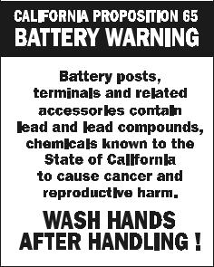
April 20, 2000 – Revised – Added Proposition 65 to front of manual.
3120727 |
– JLG Lift – |
c |

EFFECTIVITY PAGE
This page intentionally left blank.
d |
– JLG Lift – |
3120727 |

TABLE OF CONTENTS
SUBJECT - SECTION, PARAGRAPH |
PAGE NO. |
SECTION INTRODUCTION - - MAINTENANCE SAFETY PRECAUTIONS
A General . . . . . . . . . . . . . . . . . . . . . . . . . . . . . . . . . . . . . . . . . . . . . . . . . . . . . . . . . . . . . . . . . . . . . .b
B Hydraulic System Safety . . . . . . . . . . . . . . . . . . . . . . . . . . . . . . . . . . . . . . . . . . . . . . . . . . . . . . . . .b
C Maintenance . . . . . . . . . . . . . . . . . . . . . . . . . . . . . . . . . . . . . . . . . . . . . . . . . . . . . . . . . . . . . . . . . .b
SECTION 1 - SAFETY PRECAUTIONS
1.1 General . . . . . . . . . . . . . . . . . . . . . . . . . . . . . . . . . . . . . . . . . . . . . . . . . . . . . . . . . . . . . . . . . . . . . .1-1
1.2 Electrocution Hazard. . . . . . . . . . . . . . . . . . . . . . . . . . . . . . . . . . . . . . . . . . . . . . . . . . . . . . . . . . . .1-1
1.3 Transporting Machine . . . . . . . . . . . . . . . . . . . . . . . . . . . . . . . . . . . . . . . . . . . . . . . . . . . . . . . . . . .1-1
1.4 Pre-operational Safety. . . . . . . . . . . . . . . . . . . . . . . . . . . . . . . . . . . . . . . . . . . . . . . . . . . . . . . . . . .1-2
1.5 Operating Safety . . . . . . . . . . . . . . . . . . . . . . . . . . . . . . . . . . . . . . . . . . . . . . . . . . . . . . . . . . . . . . .1-3
SECTION 2 - PREPARATION AND INSPECTION
2.1 General . . . . . . . . . . . . . . . . . . . . . . . . . . . . . . . . . . . . . . . . . . . . . . . . . . . . . . . . . . . . . . . . . . . . . .2-1
2.2 Preparation For Use . . . . . . . . . . . . . . . . . . . . . . . . . . . . . . . . . . . . . . . . . . . . . . . . . . . . . . . . . . . .2-1
2.3 Delivery And Frequent Inspection. . . . . . . . . . . . . . . . . . . . . . . . . . . . . . . . . . . . . . . . . . . . . . . . . .2-1
2.4 Daily Walk-around Inspection . . . . . . . . . . . . . . . . . . . . . . . . . . . . . . . . . . . . . . . . . . . . . . . . . . . . .2-2
2.5 Daily Functional Check . . . . . . . . . . . . . . . . . . . . . . . . . . . . . . . . . . . . . . . . . . . . . . . . . . . . . . . . . .2-3
2.6 Torque Requirements . . . . . . . . . . . . . . . . . . . . . . . . . . . . . . . . . . . . . . . . . . . . . . . . . . . . . . . . . . .2-4
2.7 Battery Charging & Maintenance . . . . . . . . . . . . . . . . . . . . . . . . . . . . . . . . . . . . . . . . . . . . . . . . . .2-5
SECTION 3 - USER RESPONSIBILITIES & MACHINE CONTROLS
3.1 General . . . . . . . . . . . . . . . . . . . . . . . . . . . . . . . . . . . . . . . . . . . . . . . . . . . . . . . . . . . . . . . . . . . . . .3-1
3.2 Personnel Training . . . . . . . . . . . . . . . . . . . . . . . . . . . . . . . . . . . . . . . . . . . . . . . . . . . . . . . . . . . . .3-1
3.3 Operating Characteristics And Limitations . . . . . . . . . . . . . . . . . . . . . . . . . . . . . . . . . . . . . . . . . . .3-2
3.4 Controls And Indicators. . . . . . . . . . . . . . . . . . . . . . . . . . . . . . . . . . . . . . . . . . . . . . . . . . . . . . . . . .3-2
3.5 Jlg Pot-Hole Protection Device . . . . . . . . . . . . . . . . . . . . . . . . . . . . . . . . . . . . . . . . . . . . . . . . . . . .3-5
SECTION 4 - MACHINE OPERATION
4.1 Machine Description . . . . . . . . . . . . . . . . . . . . . . . . . . . . . . . . . . . . . . . . . . . . . . . . . . . . . . . . . . . .4-1
4.2 General . . . . . . . . . . . . . . . . . . . . . . . . . . . . . . . . . . . . . . . . . . . . . . . . . . . . . . . . . . . . . . . . . . . . . .4-1
4.3 Machine Operation . . . . . . . . . . . . . . . . . . . . . . . . . . . . . . . . . . . . . . . . . . . . . . . . . . . . . . . . . . . . .4-2
4.4 Quick-change Platform . . . . . . . . . . . . . . . . . . . . . . . . . . . . . . . . . . . . . . . . . . . . . . . . . . . . . . . . . .4-4
4.5 Transporting, Lifting And Tie Down Procedures. . . . . . . . . . . . . . . . . . . . . . . . . . . . . . . . . . . . . . .4-5
SECTION 5 - OPTIONAL EQUIPMENT
5.1 Optional Equipment . . . . . . . . . . . . . . . . . . . . . . . . . . . . . . . . . . . . . . . . . . . . . . . . . . . . . . . . . . . .5-1
5.2 Extendible Platform Operation . . . . . . . . . . . . . . . . . . . . . . . . . . . . . . . . . . . . . . . . . . . . . . . . . . . .5-2
SECTION 6 - EMERGENCY PROCEDURES
6.1 General Information. . . . . . . . . . . . . . . . . . . . . . . . . . . . . . . . . . . . . . . . . . . . . . . . . . . . . . . . . . . . .6-1
6.2 Emergency Controls And Their Location . . . . . . . . . . . . . . . . . . . . . . . . . . . . . . . . . . . . . . . . . . . .6-1
6.3 Emergency Operation . . . . . . . . . . . . . . . . . . . . . . . . . . . . . . . . . . . . . . . . . . . . . . . . . . . . . . . . . . .6-1
6.4 Incident Notification. . . . . . . . . . . . . . . . . . . . . . . . . . . . . . . . . . . . . . . . . . . . . . . . . . . . . . . . . . . . .6-2
SECTION 7 - INSPECTION AND REPAIR LOG
3120727 |
– JLG Lift – |
i |

TABLE OF CONTENTS (Continued)
LIST OF FIGURES
FIGURE NO. |
TITLE |
PAGE NO. |
2-1. Daily Walk-Around Inspection. . . . . . . . . . . . . . . . . . . . . . . . . . . . . . . . . . . . . . . . . . . . . . . . . . . . .2-3 2-2. Battery Fluid Level. . . . . . . . . . . . . . . . . . . . . . . . . . . . . . . . . . . . . . . . . . . . . . . . . . . . . . . . . . . . . .2-5 2-3. Charger Assembly and Power Cord Storage. . . . . . . . . . . . . . . . . . . . . . . . . . . . . . . . . . . . . . . . .2-5 2-4. Battery Charger Front Panel. . . . . . . . . . . . . . . . . . . . . . . . . . . . . . . . . . . . . . . . . . . . . . . . . . . . . .2-6 2-5. Lubrication Chart. . . . . . . . . . . . . . . . . . . . . . . . . . . . . . . . . . . . . . . . . . . . . . . . . . . . . . . . . . . . . . .2-7 2-6. Torque Chart. . . . . . . . . . . . . . . . . . . . . . . . . . . . . . . . . . . . . . . . . . . . . . . . . . . . . . . . . . . . . . . . . .2-8 3-1. Ground Controls.. . . . . . . . . . . . . . . . . . . . . . . . . . . . . . . . . . . . . . . . . . . . . . . . . . . . . . . . . . . . . . .3-3 3-2. Platform Controller. (OLD STYLE). . . . . . . . . . . . . . . . . . . . . . . . . . . . . . . . . . . . . . . . . . . . . . . . . .3-3 3-3. Platform Controller. (NEW STYLE). . . . . . . . . . . . . . . . . . . . . . . . . . . . . . . . . . . . . . . . . . . . . . . . .3-4 3-4. Brake Release Handle. . . . . . . . . . . . . . . . . . . . . . . . . . . . . . . . . . . . . . . . . . . . . . . . . . . . . . . . . . .3-5 3-5. JLGs Pot-Hole-Protection Device - PHP Bar Operation. . . . . . . . . . . . . . . . . . . . . . . . . . . . . . . . .3-5 3-6. Decal Locations (Front View) . . . . . . . . . . . . . . . . . . . . . . . . . . . . . . . . . . . . . . . . . . . . . . . . . . . . .3-6 3-7. Decal Locations (Rear View) . . . . . . . . . . . . . . . . . . . . . . . . . . . . . . . . . . . . . . . . . . . . . . . . . . . . . .3-7 3-8. Decal Locations (Top View) . . . . . . . . . . . . . . . . . . . . . . . . . . . . . . . . . . . . . . . . . . . . . . . . . . . . . .3-8 3-9. Decal Locations (Right/Left View) . . . . . . . . . . . . . . . . . . . . . . . . . . . . . . . . . . . . . . . . . . . . . . . . . .3-9 3-10. Wheel Load Decals (10/15/20VP) . . . . . . . . . . . . . . . . . . . . . . . . . . . . . . . . . . . . . . . . . . . . . . . . . .3-10 4-1. Quick-Change Platform Mount. . . . . . . . . . . . . . . . . . . . . . . . . . . . . . . . . . . . . . . . . . . . . . . . . . . .4-4 4-2. Forklift Truck Lifting Pockets and Machine Tie Down Bar Locations. . . . . . . . . . . . . . . . . . . . . . .4-5 5-1. Extendible Platform. (Platform shown extended) . . . . . . . . . . . . . . . . . . . . . . . . . . . . . . . . . . . . . .5-2
LIST OF TABLES
TABLE NO. |
TITLE |
PAGE NO. |
1-1 Minimum Safe Approach Distance (to energized power lines or parts) . . . . . . . . . . . . . . . . . . . .1-1 2-1 Lubrication Intervals for Various Components . . . . . . . . . . . . . . . . . . . . . . . . . . . . . . . . . . . . . . . .2-7 4-1 Maximum Rated Load Capacity (for all platforms except Extendible) . . . . . . . . . . . . . . . . . . . . . .4-2 4-2 Maximum Rated Load Capacity (for Extendible Platform*) . . . . . . . . . . . . . . . . . . . . . . . . . . . . . .4-2 4-3 Machine Interlock Switch Operating Conditions. . . . . . . . . . . . . . . . . . . . . . . . . . . . . . . . . . . . . . .4-2 4-4 Machine Gross Weights . . . . . . . . . . . . . . . . . . . . . . . . . . . . . . . . . . . . . . . . . . . . . . . . . . . . . . . . .4-6 7-1 Inspection and Repair Log . . . . . . . . . . . . . . . . . . . . . . . . . . . . . . . . . . . . . . . . . . . . . . . . . . . . . . .7-1
ii |
– JLG Lift – |
3120727 |
SECTION 1 - SAFETY PRECAUTIONS
SECTION 1. SAFETY PRECAUTIONS
1.1GENERAL
This section prescribes the proper and safe practices for major areas of machine usage which have been divided into three basic categories: Transporting, Pre-Operation and Operation. In order to promote proper usage of the machine, it is mandatory that a daily routine be established based on instruction given in this section. A maintenance program must also be established by a qualified person and must be followed to ensure that the machine is safe to operate.
The user/operator of the machine should not accept operating responsibility until this manual has been READ and UNDERSTOOD, and operating instructions of the machine under the supervision of an experienced and qualified operator, has been completed. If there is a question on application and/or operation, JLG Industries Product Safety and Reliability personnel should be consulted.
MODIFICATION OF THE MACHINE WITHOUT APPROVAL OF JLG INDUSTRIES, OR CERTIFICATION BY A NATIONALLY RECOG-
NIZED TESTING LAB TO BE IN CONFORMITY WITH APPLICABLE
OSHA REGULATIONS AND ANSI STANDARDS, AND TO BE AT
LEAST AS SAFE AS BEFORE MODIFICATION, IS PROHIBITED, AND IS A VIOLATION OF OSHA RULES.
1.2ELECTROCUTION HAZARD
Minimum safe approach distances (M.S.A.D.) to energized (exposed or insulated) power lines and parts.
DO NOT MANEUVER MACHINE OR PERSONNEL TO DISTANCE LESS THAN M.S.A.D (SEE TABLE 1-1.). ASSUME ALL ELECTRI-
CAL PARTS AND WIRING ARE ENERGIZED UNLESS KNOWN
OTHERWISE.
THIS MACHINE DOES NOT PROVIDE PROTECTION FROM CONTACT WITH OR PROXIMITY TO AN ELECTRICALLY CHARGED CONDUCTOR. MAINTAIN A CLEARANCE OF AT LEAST 10 FT. (3M) BETWEEN ANY PART OF THE MACHINE AND ANY ELECTRICAL LINE OR APPARATUS CARRYING UP TO 50,000 VOLTS. 1
FT. (0.3M) ADDITIONAL CLEARANCE IS REQUIRED FOR EVERY ADDITIONAL 30,000 VOLTS OR LESS. ALLOW FOR PLATFORM
SWAY, ROCK OR SAG AND ELECTRICAL LINE SWAYING, (SEE FOLLOWING TABLE).
.
Table 1-1. Minimum Safe Approach Distance (to energized power lines or parts)
VOLTAGE RANGE |
MINIMUM SAFE DISTANCE - |
(PHASE TO PHASE) |
Feet [m] |
|
|
0-300V |
Avoid Contact |
|
|
Over 300V to 50KV |
10 ft. [3 m] |
|
|
Over 50KV to 200KV |
15 ft. [4.6 m] |
|
|
Over 200KV to 350KV |
20 ft. [6 m] |
|
|
Over 350KV to 500KV |
25 ft. [7.6 m] |
|
|
Over 500KV to 750KV |
35 ft. [10.6 m] |
|
|
Over 750KV to 1000KV |
45 ft. [13.7 m] |
|
|
1.3TRANSPORTING MACHINE
Before transporting (hauling) the machine the user/ operator must be familiar with the proper procedures for transporting the machine (see Section 4-5), as well as the weight and size of the machine.
The user/operator should be familiar with the surrounding work area and surface before transporting the machine. The work area must be a firm surface capable of supporting the combined weight of the transport vehicle and the machine.
NOTE: Remember that the key to safe and proper usage is common sense and its careful application.
ALWAYS RELEASE THE DRIVE MOTOR BRAKES ON THE
MACHINE WHEN MANUALLY PUSHING, PULLING, OR WHEN
TRANSPORTING MACHINE BY FORK-LIFT TRUCK. THIS WILL ALLOW THE REAR DRIVE WHEELS, GEAR BOX DRIVE SHAFT
AND GEARS TO ROTATE FREELY PREVENTING ANY DAMAGE
TO THE DRIVE SYSTEM.
IF MACHINE IS PLACED ON A TRANSPORT VEHICLE, REENGAGE THE BRAKES IN COMBINATION WITH PROPER MACHINE TIE DOWN, TO RESTRAIN MACHINE FROM ANY MOVEMENT DURING TRANSPORT.
ALWAYS REMEMBER TO RE-ENGAGE THE BRAKE SYSTEM
BEFORE OPERATING MACHINE.
FAILURE TO COMPLY WITH SAFETY PRECAUTIONS LISTED IN THIS SECTION AND ON MACHINE COULD RESULT IN MACHINE
DAMAGE, PERSONAL INJURY OR DEATH AND IS A SAFETY VIOLATION.
3120727 |
– JLG Lift – |
1-1 |

SECTION 1 - SAFETY PRECAUTIONS
LIFT MACHINE AT DESIGNATED
LIFTING POINTS ONLY
1.4PRE-OPERATIONAL SAFETY
•READ YOUR MANUAL. UNDERSTAND WHAT YOU’VE READ - THEN BEGIN OPERATIONS.
•ALLOW ONLY THOSE AUTHORIZED AND QUALIFIED PERSONNEL TO OPERATE MACHINE WHO HAVE DEMONSTRATED THAT THEY UNDERSTAND SAFE AND PROPER OPERATION AND MAINTENANCE OF THE UNIT.
•AN OPERATOR MUST NOT ACCEPT OPERATING RESPONSIBILITIES UNTIL ADEQUATE TRAINING HAS BEEN GIVEN BY COMPETENT AND AUTHORIZED PERSONS.
•BEFORE OPERATION CHECK WORK AREA FOR OVERHEAD ELECTRIC LINES. (SEE ELECTROCUTION HAZARD, SECTION 1-2.)
•STUDY THE WORK AREA FOR AREAS TO AVOID SUCH AS; SURFACE EDGES THAT DROP-OFF, HOLES OR DIPS IN SURFACE, OR ANY UNLEVEL AREAS WHICH COULD CAUSE THE UNIT TO TIP OVER.
•ALSO BEFORE OPERATION CHECK WORK AREA FOR MACHINE TRAFFIC SUCH AS FORKLIFTS, CRANES, AND OTHER CONSTRUCTION EQUIPMENT.
•ENSURE THAT OPERATORS OF OTHER OVERHEAD AND FLOOR LEVEL MACHINES ARE AWARE OF THE AERIAL PLATFORMS PRESENCE. DISCONNECT POWER TO OVERHEAD CRANES. BARRICADE FLOOR AREA IF NECESSARY.
•PRECAUTIONS TO AVOID ALL KNOWN HAZARDS IN THE WORK AREA MUST BE TAKEN BY THE OPERATOR AND HIS SUPERVISOR BEFORE STARTING THE WORK.
•DO NOT OPERATE THIS MACHINE UNLESS IT HAS BEEN SERVICED AND MAINTAINED ACCORDING TO THE MANUFACTURERS SPECIFICATIONS AND SCHEDULE.
•ENSURE DAILY INSPECTION AND FUNCTION CHECK IS PERFORMED PRIOR TO PLACING MACHINE INTO OPERATION. HAVE AUTHORIZED PERSONNEL TAKE ANY NECESSARY CORRECTIVE ACTION BEFORE PLACING MACHINE INTO OPERATION.
•NEVER DISABLE OR MODIFY ANY SAFETY DEVICE. ANY MODIFICATION OF THE MACHINE IS A SAFETY VIOLATION AND IS A VIOLATION OF OSHA AND ANSI RULES.
•DO NOT OPERATE MACHINE WHEN EXPOSED TO HIGH WIND, RAIN OR SNOW.
•NEVER OPERATE OR RAISE PLATFORM WHEN MACHINE IS ON A TRUCK OR OTHER VEHICLE.
•APPROVED HEAD GEAR (I.E. HARD HAT, ETC.) MUST BE WORN WHEN REQUIRED BY ALL OPERATING AND GROUND PERSONNEL.
•READ AND OBEY ALL DANGER, WARNINGS, CAUTIONS AND OPERATING INSTRUCTIONS ON MACHINE AND IN THIS MANUAL.
•BE FAMILIAR WITH LOCATION AND OPERATION OF GROUND CONTROLS AND EMERGENCY CONTROLS.
1-2 |
– JLG Lift – |
3120727 |

SECTION 1 - SAFETY PRECAUTIONS
ALWAYS LOOK IN DIRECTION OF TRAVEL
1.5OPERATING SAFETY
FAILURE TO OBSERVE THE FOLLOWING TIPPING HAZARD INSTRUCTIONS COULD CAUSE THE UNIT TO TIP OVER OR BE
HARD TO CONTROL WHEN BEING MOVED, WHICH COULD
RESULT IN SERIOUS INJURY OR DEATH DUE TO BEING PINNED
OR CRUSHED BY THE UNIT.
Driving Safety
•READ YOUR MANUAL, UNDERSTAND WHAT YOU’VE READ - THEN BEGIN OPERATIONS.
•WATCH FOR OBSTRUCTIONS AROUND MACHINE AND OVERHEAD WHEN MOVING.
•CHECK TRAVEL PATH FOR PERSONS, HOLES, BUMPS, DROP-OFFS, OBSTRUCTIONS, DEBRIS, AND COVERINGS WHICH MAY CONCEAL HOLES AND OTHER HAZARDS, AS TIPPING COULD OCCUR.
•BEFORE MOVING MACHINE ON FLOORS AND OTHER SURFACES, CHECK ALLOWABLE CAPACITY OF SURFACES.
•DO NOT OPERATE MACHINE ON SOFT FOOTING THAT WILL ALLOW THE WHEELS TO SETTLE INTO OR BREAK THROUGH SURFACE, AS TIPPING WILL OCCUR.
•NEVER POSITION THE UNIT SIDEWAYS ON A SLOPE.
•USE CAUTION AND CHECK CLEARANCES WHEN MOVING MACHINE IN RESTRICTED OR CLOSE QUARTERS.
•ALWAYS USE AN ASSISTANT WHEN MOVING MACHINE IN AREAS WHERE VISION IS OBSTRUCTED.
General Operating Safety
•KEEP NON-OPERATING PERSONNEL AT LEAST 6 FEET (1.8 M) AWAY FROM MACHINE DURING OPERATIONS.
•DO NOT OPERATE ANY MACHINE ON WHICH DANGER, WARNING, CAUTION OR INSTRUCTION PLACARDS OR DECALS ARE MISSING OR ILLEGIBLE.
•NEVER EXCEED MANUFACTURERS RATED PLATFORM CAPACITY - REFER TO CAPACITY DECAL ON MACHINE.
•NEVER OPERATE A MALFUNCTIONING MACHINE. IF A MALFUNCTION OCCURS, SHUT DOWN THE MACHINE, RED TAG IT, AND NOTIFY PROPER AUTHORITIES.
NEVER OPERATE ON SOFT
OR UNEVEN SURFACES
3120727 |
– JLG Lift – |
1-3 |
SECTION 1 - SAFETY PRECAUTIONS
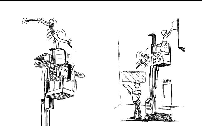
ALWAYS STAND ON PLATFORM FLOOR
NOT ON BOXES, PLANKS OR RAILINGS
•ALL PERSONNEL MUST STAND CLEAR WHEN PLATFORM IS BEING RAISED OR LOWERED. BE SURE TO WATCH FOR OVERHEAD AND OTHER OBSTRUCTIONS.
•CHECK CLEARANCES ABOVE, ON SIDES AND BOTTOM OF PLATFORM WHEN RAISING AND LOWERING PLATFORM.
•NEVER USE THE MAST TO GAIN ACCESS TO OR LEAVE PLATFORM.
•DO NOT ATTACH OVERHANGING LOADS TO THE PLATFORM OR INCREASE THE PLATFORM SIZE WITH UNAUTHORIZED DECK EXTENSIONS OR ATTACHMENTS.
•DO NOT TIE OFF MACHINE TO ANY ADJACENT STRUCTURE. NEVER ATTACH WIRE, CABLE OR ANY SIMILAR ITEMS TO PLATFORM.
•TRANSFERS BETWEEN A STRUCTURE AND THE AERIAL PLATFORM EXPOSE OPERATING PERSONNEL TO FALL POTENTIALS. THIS PRACTICE SHOULD BE DISCOURAGED WHEREVER POSSIBLE. WHERE TRANSFER MUST BE ACCOMPLISHED TO PERFORM THE JOB, AN APPROVED FALL PROTECTION DEVICE AND TWO SAFETY LANYARDS WILL BE USED. ONE LANYARD SHOULD BE ATTACHED TO THE AERIAL PLATFORM. THE OTHER TO THE STRUCTURE. THE SAFETY LANYARD THAT IS ATTACHED TO THE
KEEP EVERYONE CLEAR OF A
WORKING PLATFORM
AERIAL PLATFORM SHOULD NOT BE DISCONNECTED UNTIL SUCH TIME AS THE TRANSFER TO THE STRUCTURE IS COMPLETE. WHEN RE-ENTER- ING THE PLATFORM THIS PROCEDURE MUST BE PERFORMED IN REVERSE. TO AVOID FALLING - USE EXTREME CAUTION WHEN ENTERING OR LEAVING PLATFORM ABOVE GROUND. ENTER OR EXIT THRU GATE ONLY. PLATFORM FLOOR MUST BE WITHIN 1 FOOT (0.3 M) OF ADJACENT - SAFE AND SECURE - STRUCTURE. ALLOW FOR ANY VERTICAL MOVEMENT OF PLATFORM (UP OR DOWN) WHEN ENTERING OR LEAVING PLATFORM.
•NO HORSEPLAY IS PERMITTED IN PLATFORM.
•DO NOT ALLOW PERSONNEL TO TAMPER WITH, SERVICE, OR OPERATE THIS MACHINE FROM THE GROUND WITH PERSONNEL IN PLATFORM EXCEPT IN AN EMERGENCY.
•DURING OPERATION KEEP ALL BODY PARTS INSIDE PLATFORM RAILINGS.
•NEVER POSITION LADDERS, STEPS, OR SIMILAR ITEMS ON UNIT TO PROVIDE ADDITIONAL REACH FOR ANY PURPOSE.
1-4 |
– JLG Lift – |
3120727 |
SECTION 2 - PREPARATION AND INSPECTION
SECTION 2. PREPARATION AND INSPECTION
2.1GENERAL
This section provides the necessary information needed by those personnel that are responsible to place the machine in operation readiness, and lists checks that are performed prior to use of the machine. It is important that the information contained in this section be read and understood before any attempt is made to operate the machine. Ensure that all the necessary inspections have been completed successfully before placing the machine into service. These procedures will aid in obtaining maximum service life and safe operation.
SINCE THE MACHINE MANUFACTURER HAS NO DIRECT CON-
TROL OVER THE FIELD INSPECTION AND MAINTENANCE, THIS
IS THE RESPONSIBILITY OF THE OWNER/OPERATOR.
2.2PREPARATION FOR USE
Before a new machine is put into operation it must be carefully inspected for any evidence of damage resulting from shipment and inspected periodically thereafter, as outlined in Section 2-3, Delivery and Frequent Inspection. The unit should be thoroughly checked for hydraulic leaks during initial start-up and run. A check of all components should be made to assure their security.
All preparation necessary to place the machine in operation readiness status are the responsibility of management personnel. Preparation requires good common sense, (i.e. lift works smoothly) coupled with a series of visual inspections. The mandatory requirements are given in Section 2-4, Daily Walk Around Inspection.
It should be assured that the items appearing in the Delivery and Frequent Inspection and Functional Check are complied with prior to putting the machine into service.
2.3DELIVERY AND FREQUENT INSPECTION
The following check list provides a systematic inspection to assist in detecting defective, damaged, or improperly installed parts. The check list denotes the items to be inspected and conditions to examine. Frequent inspection shall be performed every three (3) months or 150 hours, or more often when required by environment, severity, and frequency of usage.
Platform Assembly
Properly secured; no visible damage; free of dirt and debris. Platform gate functions properly.
Mast
No visible damage, abrasions and/or distortions; no binding; mast sections free of dirt or other foreign material. Sequencing cables properly secured; no visible damage; proper cable tension.
Mast Chains & Cables
No visible damage; proper chain/cable tension; evidence of proper lubrication. Chain/cable sheaves, sheave pins and rollers properly secured; no visible damage.
Platform Controller/(Power) Cable(s)
No visible damage; cable properly tensioned and seated in control cable sheaves; control cable sheaves not damaged and rotating freely.
Lift Cylinder (check w/mast extended)
No rust, nicks, scratches or foreign material on piston rod. No leakage.
Frame
No visible damage; loose or missing hardware (top and underside).
Drive Wheels and Front Casters
Casters free rolling; no loose or missing parts; no visible damage. Drive wheel hub retainer ring secure; no damage to wheel tread; electric drive motors secure; no loose or missing wires.
Hydraulic Oil Supply
Check the hydraulic oil level of the hydraulic fluid reservoir located in the lower access hole on the rear cover. Maintain an oil level to the “Fill To Line” indicator on the side of reservoir.
If fluid level is low, see Table 2-1. “Lubrication Interval Chart” for information on hydraulic oil.
3120727 |
– JLG Lift – |
2-1 |

SECTION 2 - PREPARATION AND INSPECTION
Controls - (Platform and Ground)
Controls operable; no visible damage; placards secure and legible.
Batteries
Proper electrolyte level; cable connections tight; no visible damage; no corrosion at battery cable connections.
Pump Motor/Hydraulic Pump/Valves andLines
No leakage; units secure.
Placards
No visible damage; placards secure and legible.
2.4DAILY WALK-AROUND INSPECTION
It is the user/operator’s responsibility to inspect the machine before the start of each work day. It is recommended that each user/operator inspect the machine before operation, even if the machine has already been put into service under another user/operator. This Daily Walk-Around Inspection is the preferred method of inspection.
General
Begin the “Walk-Around Inspection” at item one listed following. Continue around machine checking each item in sequence for the conditions listed in the “Walk-Around Inspection Check list”.
TO AVOID INJURY DO NOT OPERATE MACHINE UNTIL ALL MAL-
FUNCTIONS HAVE BEEN CORRECTED. USE OF A MALFUNC-
TIONING MACHINE IS A SAFETY VIOLATION.
TO AVOID POSSIBLE INJURY, BE SURE MACHINE POWER IS
“OFF” DURING “WALK-AROUND INSPECTION”.
NOTE: Do not overlook visual inspection of the base frame underside. Check this area for objects or debris which could cause extensive machine damage.
1.Drive and Caster Wheels - Properly secured and lubricated. Check for any visible damage or debris, stuck to or around wheels.
2.Base Frame - No visible damage; drive wheel motor components properly secured; JLG’s Pot-Hole-Pro- tection System components secure; no loose wires or cables dangling below the base; bubble level in place and functioning properly.
3.Battery/Battery Charger - Proper battery electrolyte level, cables secure, no damage or corrosion.
4.Motor/Pump/Reservoir Unit - Properly secured, no visible damage, no evidence of hydraulic leaks. Hydraulic oil level should be filled level with the full line, (“Fill To Line”) on the side of the hydraulic reservoir. Also check that reservoir cap is properly secured.
5.Ground Controls - Properly secured, no loose or missing parts, no visible damage; key switch operable, no visible damage; placards secure and legible; emergency stop switch, no visible damage and properly set for operation.
6.Mast Assembly - Mast sections properly secured, no visible damage to mast sections, no loose or missing parts, slide pads properly secured. Mast chains/cables properly secured and lubricated. Sequencing cables properly secured and undamaged. Platform control and power cables (on side of mast), no visible damage; cables properly tensioned and seated in sheaves; cable sheaves not damaged and rotating freely. Elevation/Speed Limit switch (top inside of mast section 1) secure and working properly.
7.Manual Brake Release Control - Handle secure and undamaged; cables attached properly; control in working order.
8.Platform Assembly - Secure to mast; All railings securely attached; no loose or missing parts, no visible damage; sliding entry bar in proper working order. Platform gate working properly, no visible sign of damage (if so equipped).
9.Platform Controls - Platform up/down, function enable and horn buttons on faceplate no loose or missing parts, no visible damage. Joystick control secure. Placards secure and legible, emergency shut-off button set for operation. Control markings legible; Operators manual enclosed in manual storage box.
In addition to the Daily Walk-Around Inspection, be sure to include the following as part of the daily inspection:
Batteries Charged
Start each day with fully charged batteries. (See Section 2- 7. “Battery Charging & Maintenance”)
Overall Cleanliness
Keep oil, grease, water, etc. wiped from standing surfaces and hand holds.
Placards
Keep all information and operating placards clean and unobstructed. Cover areas where placards are present when using the machine for spraying paint or any material which could cover these surfaces and reduce legibility.
2-2 |
– JLG Lift – |
3120727 |
 Loading...