


Integrated Device Technology Inc IDT49C465PQFB, IDT49C465AG, IDT49C465AGB, IDT49C465APQF, IDT49C465APQFB Datasheet
...
|
|
|
|
|
|
|
|
|
|
|
|
|
|
|
|
|
|
32-BIT FLOW-THRU |
IDT49C465 |
|
|
|
|
|
|
|
|
|
|
|
|
|
|
|
|
|
|
ERROR DETECTION |
IDT49C465A |
|
|
|
|
|
|
|
|
|
|
|
|
|
|
|
|
|
|
AND CORRECTION UNIT |
|
Integrated Device Technology, Inc. |
|
|
|||||||||||||||||
|
|
|
|||||||||||||||||
|
|
|
|
|
|
|
|
|
|
|
|
|
|
|
|
|
|
|
|
|
|
|
|
|
|
|
|
|
|
|
|
|
|
|
|
|
|
|
|
FEATURES
•32-bit wide Flow-thruEDC™ unit, cascadable to 64 bits
•Single-chip 64-bit Generate Mode
•Separate system and memory buses
•On-chip pipeline latch with external control
•Supports bidirectional and common I/O memories
•Corrects all single-bit errors
•Detects all double-bit errors, some multiple-bit errors
•Error Detection Time — 12ns
•Error Correction Time — 14ns
•On chip diagnostic registers.
•Parity generation and checking on system data bus
•Low power CMOS — 100mA typical at 20MH Z
•144-pin PGA and PQFP packages
•Military product compliant to MIL-STD 883, Class B
DESCRIPTION
The IDT49C465/A is a 32-bit, two-data bus, Flow-thruEDC unit. The chip provides single-error correction and two and three bit error detection of both hard and soft memory errors. It can be expanded to 64-bit widths by cascading 2 units, without the need for additional external logic. The FlowthruEDC has been optimized for speed and simplicity of control.
The EDC unit has been designed to be used in either of two configurations in an error correcting memory system. The bidirectional configuration is most appropriate for systems using bidirectional memory buses. A second system configuration utilizes external octal buffers, and is well suited for systems using memory with separate I/O buses.
The IDT49C465/A supports partial word writes, pipelining and error diagnostics. It also provides parity protection for data on the system side.
SIMPLIFIED FUNCTIONAL BLOCK DIAGRAM
MD0–31 |
|
|
|
|
MD |
|
|
|
Latch |
Memory |
|
|
|
||
|
|
Checkbit |
|
|
|
Generator |
|
MLE |
|
|
|
CBI0–7 |
Checkbit |
Mux |
|
Latch |
|||
|
|||
PCBI0–7 |
|
CONTROL |
|
|
Pipeline Latch |
||
SD0–31 |
|
||
|
|
||
|
SD |
Byte |
|
|
Mux |
||
|
Latch |
||
|
|
||
SLE |
|
|
|
PLE |
|
CONTROL |
|
|
|
The IDT logo is a registered trademark and Flow-thruEDC is a trademarkof Integrated Device Technology Inc.
MILITARY AND COMMERCIAL TEMPERATURE RANGES
©1995 Integrated Device Technology, Inc. |
11.7 |
Correct
Logic
Syndrome Generator |
|
|
|
|
|
|
|
ERR |
|
|
|
|
|
|
|
||
|
|
Expansion Logic |
|
|
|
|
||
|
|
|
|
|
|
|
|
|
|
|
|
|
|
Detect |
|
|
|
|
|
|
|
|
|
Logic |
|
MERR |
|
|
|
|
|
|
|
|
|
|
|
|
|
|
|
|
|
|
|
|
|
|
|
|
|
|
|
|
CONTROL |
|
|
|
|
|||
|
|
|
|
|
|
|
|
|
|
|
|
|
|
|
|
|
|
System |
|
|
|
Mux |
|
CBO0–7 |
||
Checkbit |
|
|
|
|
||||
|
|
|
|
|
||||
Generator |
|
|
|
|
|
|
||
|
|
|
|
|
|
|
|
2552 drw 01 |
|
|
|
|
|
|
|
|
|
|
|
|
|
|
|
|
|
|
|
|
|
|
|
CONTROL |
|
||
AUGUST 1995
DSC-9028/7
1
IDT49C465/A |
|
|
|
32-BIT FLOW-THRU ERROR DETECTION AND CORRECTION UNIT |
MILITARY AND COMMERCIAL TEMPERATURE RANGES |
||
|
|
|
|
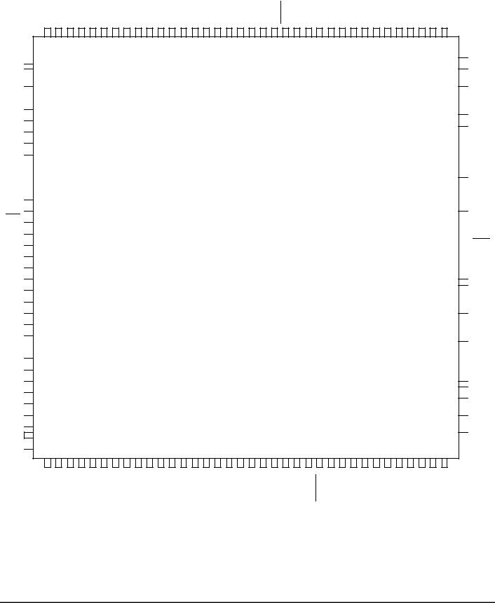
PIN CONFIGURATION |
|
|
|
VCC SD4 BE0 SD3 SD2 SD1 SD0 |
PCBI7 PCBI6 PCBI5 PCBI4 PCBI3 PCBI2 PCBI1 |
PCBI0 CODE ID 1 CODE ID 0 GND GND MODE 1 MODE 0 |
MERR ERR SYO7 SYO6 SY05 SY04 GND SY03 SYO2 SYO1 SYO0 MD0 MD1 MD2 VCC |
72 VCC 
 73
73
SD5 
SD6 

SD7 
SD8 

SD9 
SD10 

SD11 
GND 

BE1 
SD12 

SD13 
SD14 

SD15 
SLE 

PLE 
SOE 

GND 
SD16 

SD17 
SD18 

SD19 
BE2 

SD20 
SD21 

SD22 
GND 

SD23 
SD24 

SD25 
SD26 

SD27 
BE3 

SD28 
VCC
VCC  108
108
109
49C465Y
PQ144-2
37
36
 VCC
VCC
 VCC
VCC
 MD3
MD3
 MD4
MD4
 MD5
MD5
 MD6
MD6
 MD7
MD7
 MD8
MD8
 MD9
MD9
 GND
GND
 MD10
MD10
 MD11
MD11
 MD12
MD12
 MD13
MD13
 MD14
MD14
 MD15
MD15
 MLE
MLE
 MOE
MOE
 GND
GND
 MD16
MD16
 MD17
MD17
 MD18
MD18
 MD19
MD19
 MD20
MD20
 MD21
MD21
 MD22
MD22
 MD23
MD23
 GND
GND
 MD24
MD24
 MD25
MD25
 MD26
MD26
 MD27
MD27
 MD28
MD28
 MD29
MD29
 MD30
MD30
1
 VCC
VCC
144
VCC |
SD29 SD30 SD31 |
CBO0 |
CBO1 CBO2 |
CBO3 |
CBOE CBO4 CBO5 |
CBO6 |
CBO7 PSEL |
PERR P3 |
P2 |
GND GND P1 |
P0 |
MODE 2 |
SYNCLK SCLKEN CLEAR CBI0 |
CBI1 |
CBI2 |
CBI3 |
GND CBI4 |
CBI5 CBI6 |
CBI7 MD31 VCC |
2552 drw 02
PQFP
TOP VIEW
11.7 |
2 |

IDT49C465/A |
|
32-BIT FLOW-THRU ERROR DETECTION AND CORRECTION UNIT |
MILITARY AND COMMERCIAL TEMPERATURE RANGES |
PIN CONFIGURATION
15 |
VCC |
SD 2 |
PCBI 6 PCBI 5 PCBI 3 |
CODE CODE MODE |
MERR ERR |
SYO 5 SYO 3 SYO 1 |
MD 1 |
VCC |
||
ID 1 |
ID0 |
1 |
||||||||
14 |
SD 6 |
SD 4 |
|
SD 1 |
PCBI 7 PCBI 4 PCBI 1 PCBI 0 MODE SYO 6 SYO 4 SYO 2 |
|
MD 0 |
MD 2 |
VCC |
MD 5 |
|||||||||||||||
|
|
|
|
|
0 |
|
|
|
|
|
|
|
|
|
|
|
|
|
|||||||
13 |
SD 9 |
SD 5 |
|
BE 0 |
|
SD 3 |
|
SD 0 |
|
PCBI 2 |
GND |
GND |
|
SYO 7 |
|
GND |
|
SYO 0 |
|
VCC |
|
MD 3 |
MD 6 |
MD 9 |
|
|
|
|
|
|
|
|
|
|
|
|
|
|
|
|
|
|
|
|
|
|
|
|
|
|
|
12 |
SD 11 |
SD 7 |
|
VCC |
|
|
|
|
|
|
|
|
|
|
|
|
|
|
|
|
|
MD 4 |
MD 8 |
GND |
|
|
|
|
|
|
|
|
|
|
|
|
|
|
|
|
|
|
|
|
|
|
|
|
|
|
|
11 |
SD 12 |
SD 10 |
|
SD 8 |
|
|
|
|
|
|
|
|
|
|
|
|
|
|
|
|
|
MD 7 |
MD 10 |
MD 11 |
|
|
|
|
|
|
|
|
|
|
|
|
|
|
|
|
|
|
|
|
|
|
|
|
|
|
|
10 |
SD 15 |
BE 1 |
|
GND |
|
|
|
|
|
|
|
|
|
|
|
|
|
|
|
|
|
MD 12 |
MD 13 |
MD 15 |
|
|
|
|
|
|
|
|
|
|
|
|
|
|
|
|
|
|
|
|
|
|
|
|
|
|
|
9 |
SLE |
SD 13 |
|
SD 14 |
|
|
|
|
|
|
|
|
|
|
|
|
|
|
|
|
|
MOE |
MD 14 |
MLE |
|
|
|
|
|
|
|
|
|
|
|
|
G144-2 |
|
|
|
|
|
|
|
|||||||
8 |
SOE |
PLE |
|
GND |
|
|
|
|
|
|
|
|
|
GND |
MD 17 |
MD 16 |
|
||||||||
|
|
|
|
|
|
|
|
|
|
|
|
|
|
|
|
|
|
|
|||||||
|
|
|
|
|
|
|
|
|
|
|
|
|
|
|
|
|
|
|
|
|
|
|
|
|
|
7 |
SD 17 |
SD 19 |
|
SD 16 |
|
|
|
|
|
|
|
|
|
|
|
|
|
|
|
|
|
MD 20 |
MD 21 |
MD 18 |
|
|
|
|
|
|
|
|
|
|
|
|
|
|
|
|
|
|
|
|
|
|
|
|
|
|
|
6 |
SD 18 |
BE 2 |
|
SD 20 |
|
|
|
|
|
|
|
|
|
|
|
|
|
|
|
|
|
GND |
MD 23 |
MD 19 |
|
|
|
|
|
|
|
|
|
|
|
|
|
|
|
|
|
|
|
|
|
|
|
|
|
|
|
5 |
SD 21 |
SD 22 |
|
SD 25 |
|
|
|
|
|
|
|
|
|
|
|
|
|
|
|
|
|
MD 27 |
MD 25 |
MD 22 |
|
|
|
|
|
|
|
|
|
|
|
|
|
|
|
|
|
|
|
|
|
|
|
|
|
|
|
4 |
GND |
SD 24 |
BE 3 |
NC* |
|
|
|
|
|
|
|
|
VCC |
MD 28 |
MD 24 |
|
|
|
|
|
|
|
|
|
|
||||||
3 |
SD 23 |
SD 26 |
SD 28 |
VCC |
CB0 0 |
CBOE CB0 7 |
GND |
GND |
SCLK |
GND |
CB1 6 |
CB1 7 |
MD 30 |
MD 26 |
|
|
|
|
|
|
|
|
|
|
|
EN |
|
|
|
|
|
2 |
SD 27 |
VCC |
SD 29 |
SD 31 |
CB0 2 |
CB0 4 |
CB0 6 |
P3 |
MODE SYN- |
CB1 0 |
CB1 3 |
CB1 4 |
MD 31 |
MD 29 |
|
|
|
|
|
|
|
|
|
|
2 |
CLK |
|
|
|
|
|
1 |
VCC |
SD 30 |
CB0 1 |
CB0 3 |
CB0 5 |
PSEL PERR |
P2 |
P1 |
P0 |
CLEAR CB1 1 |
CB1 2 |
CB1 5 |
VCC |
||
|
A |
B |
C |
D |
E |
F |
G |
H |
J |
K |
L M |
N |
P |
R |
|
*Tied to Vcc internally
PGA (CAVITY UP)
TOP VIEW
2552 drw 03
11.7 |
3 |

7.11
4
ERR 

MERR 
SYO0–7 

PLE 
SOE 
BE0–3 
SD0–31 
SLE 
PSEL 
4
P0–3
4
PERR 
/ERR
SYNCLK 
SCLKEN 
CLEAR 
ERROR |
|
INTERNAL 8 |
|
DETECT |
|
||
MUX |
FINAL |
||
8 |
|
SYNDRO |
|
ME |
|
8 |
8 |
MUX |
|
8
4
1 OF 4 |
PIPE |
BYTES |
|
|
LATCH |
SD
LATCH
PCBI 0–7
SYNDROME GENERATOR
MUX
Dashed Line = Diagnostic path
|
|
8 |
|
8 |
MUX |
CHECK |
|
|
|
BIT |
8 MUX |
|
|
LATCH |
|
8
MD
CHECKBIT 
 GENERATOR
8
MD
ERROR LATCH CORRECT
ERROR DATA LATCH

|
CLEAR |
DIAGNOSTIC |
INTERNAL SYNCLK |
LATCHES |
BYTE MUX
BE 0–3 4
4 PARITY GEN
GEN 
PARITY CHECK
CHECK
MUX

SD 8
CHECKBIT
GENERATOR
|
SD |
|
CHECKBIT |
8 |
GENERATOR |
MUX

8
8
8
INTERNAL SYNCLK
CODE ID 0,1 |
2 |
CONTROL |
|
||
MODE0–2 |
3 |
LOGIC |
|
|
|
04 drw 2552 |
|
|
8
CBI0–7
 MLE
MLE
MD0–31
MOE
CBO0–7
CBOE
PCBI0–7
DIAGRAM BLOCK FUNCTIONAL DETAILED |
IDT49C465/A UNIT CORRECTION AND DETECTION ERROR THRU-FLOW BIT-32 |
RANGES TEMPERATURE COMMERCIAL AND MILITARY

IDT49C465/A |
|
32-BIT FLOW-THRU ERROR DETECTION AND CORRECTION UNIT |
MILITARY AND COMMERCIAL TEMPERATURE RANGES |
SYSTEM CONFIGURATIONS
The IDT49C465 EDC unit can be used in various configurations in an EDC system. The basic configurations are shown below.
Figure 1 illustrates a bidirectional configuration, which is most appropriate for systems using bidirectional memory buses. It is the simplest configuration to understand and use. During a correction cycle, the corrected data word can be simultaneously output on both the system bus and memory bus. Logically, no other parts are required for the correction function. During partial-word-write operations, the new bytes are internally combined with the corrected old bytes for checkbit generation and writing to memory.
CPU |
SD |
MD |
MEMORY |
|
I/O |
I/O |
|||
|
|
EDC
CBI
CHECKBITS
CBO 
2552 drw 05
Figure 1. Common I/O Configuration
Figure 3 illustrates a third configuration which utilizes external buffers and is also well suited for systems using memory with separate I/O buses. Since data from memory does not need to pass through the part on every cycle, the EDC system may operate in “bus-watch” mode. As in the separate I/O configuration, corrected data is output on the SD outputs.
MEMORY |
CHECKBIT |
MEMORY |
||
INPUT BUS |
OUTPUT BUS |
|||
|
I/O |
|||
|
|
|
||
|
CBO |
CBI |
|
|
|
SD |
MD |
|
|
|
|
EDC |
|
|
EXT. BUFFER |
|
|
EXT. BUFFER |
|
EXT.BUFFER |
|
|
|
|
|
CPU BUS |
|
||
|
|
|
2552 drw 07 |
|
Figure 3. Bypassed Separate I/O Configuration |
||||
Figure 2 illustrates a separate I/O configuration. This is appropriate for systems using separate I/O memory buses. This configuration allows separate input and output memory buses to be used. Corrected data is output on the SD outputs for the system and for re-write to memory. Partial word-write bytes are combined externally for writing and checkbit generation.
Figure 4 illustrates the single-chip generate-only mode for very fast 64-bit checkbit generation in systems that use separate checkbit-generate and detect-correct units. If this is not desired, 64-bit checkbit generation and correction can be done with just 2 EDC units. 64-bit correction is also straightforward, fast and requires no extra hardware for the expansion.
CPU
|
|
|
|
|
|
.EXT |
|
|
MEMORY |
||
|
|
|
|
|
|
|
|||||
|
|
|
|
|
|
BUFFER |
|||||
|
|
|
|
|
|
INPUTS |
|||||
|
|
|
|
|
|
|
|
|
|
|
|
|
|
|
|
|
|
|
|
|
|
|
|
SD
MEMORY
MD OUTPUTS
EDC
CBI
CHECKBITS
CBO
2552 drw 06
Figure 2. Separate I/O Configuration
|
|
CHECK |
|
CHECK |
|
|
|
||
|
|
BITS OUT |
|
BITS IN |
MEMORY |
|
|||
|
|
|
|
|
|
|
OUTPUT BUS |
|
|
MEMORY |
|
MEMORY |
|
|
|
||||
INPUT BUS |
|
INPUT BUS |
|
|
|
||||
|
|
|
|
|
|
|
|
|
|
|
|
CBO |
|
|
|
|
CBI |
|
|
|
|
|
|
|
|
|
|
|
|
|
|
64-BIT |
|
|
|
|
LOWER |
UPPER |
|
|
|
GEN. |
|
|
|
|
|
||
|
|
ONLY |
|
|
|
|
DATA |
DATA |
|
|
|
EDC |
|
|
|
|
EDC |
EDC |
|
|
|
|
|
|
|
|
|
|
|
|
|
|
|
|
|
|
|
|
|
BUFFER |
|
|
|
BUFFER |
|
|
BUFFER |
BUFFER |
|
|
|
|
|
|
|
|
|
|
|
CPU BUS |
2552 drw 08 |
|
Figure 4. Separate Generate/Correction Units
with 64-Bit Checkbit Generation
11.7 |
5 |

IDT49C465/A |
|
32-BIT FLOW-THRU ERROR DETECTION AND CORRECTION UNIT |
MILITARY AND COMMERCIAL TEMPERATURE RANGES |
FUNCTIONAL DESCRIPTION
The error detection/correction codes consist of a modified
Hamming code; it is identical to that used in the IDT49C460.
32-BIT MODE (CODE ID 1,0=00)
VCC 
8 |
CHECKBITS–OUT |
|
|
PCBI |
CBO |
CBI7 |
7 |
|
|
CHECKBITS–IN |
SYO |
CBI0–6 |
|
7 |
7 SYNDROME–OUT |
EDC
2552 drw 09
Figure 5. 32-Bit Mode
64-BIT MODE (CODE ID 1,0=10 & 11)
The expansion bus topology is shown in Figure 6. This topology allows the syndrome bits used by the correction logic to be generated simultaneously in both parts used in the expansion. During a 64-bit detection or correction operation,
“Partial-Checkbit” data and “Partial-Syndrome” data is simultaneously exchanged between the two EDC units in opposite directions on dedicated expansion buses. This results in very short 64-bit detection and correction times.
8PARTIAL–CHECKBITS–OUT (11) (CORRECTION ONLY)
|
PCBI |
CBO |
8 |
PARTIAL–CHECKBITS–OUT (10) |
PCBI |
CBO |
|
8 |
FINAL |
||||
|
|
|
|
|
|
|
|||||||
|
|
|
|
(GENERATE ONLY) |
|
|
|
|
|
|
CHECKBITS–OUT |
||
CHECKBITS–IN 8 |
CBI |
SYO |
8 |
PARTIAL–SYNDROME |
|
CBI |
SYO |
|
|
|
|||
|
|
|
|
|
|
|
|
|
|||||
|
|
|
|
(DETECT/CORRECT ONLY) |
|
|
|
|
|
|
|
||
|
|
|
|
|
|
|
|
|
|
ERR |
|
(DETECT AND CORRECT) |
|
|
LOWER EDC |
|
|
|
|
|
UPPER EDC |
|
|||||
|
|
|
|
|
|
|
|
|
|||||
(CODE ID 1,0 = 10) |
|
|
|
(CODE ID 1,0 = 11) |
|
2552 drw 10 |
|||||||
|
|
|
|
|
|
|
|
|
|
|
|
|
|
|
|
Figure 6. 64-Bit Mode — 2 Cascaded IDT49C465 Devices |
|
|
|
|
|||||||
64-BIT GENERATE-ONLY MODE (CODE ID 1,0=01) |
|
|
|
|
|
|
|
|
|||||
If the Identity pins CODE ID 1,0 = 01, a single EDC is placed |
device on the SD0-31 inputs. This provides the device with the |
||||||||||||
in the 64-bit “Generate-only” mode. In this mode, the lower 32 |
full 64-bit word from |
memory. The |
resultant generated |
||||||||||
bits of the 64-bit data word enter the device on the MD0-31 |
checkbits are output on the CBO0-7 outputs. The generate |
||||||||||||
inputs and the upper 32-bits of the 64 bit data word enter the |
time is less than that resulting from using a 2-chip cascade. |
||||||||||||
|
|
|
|
|
|
|
|
|
|
|
|||
LOWER 32 BITS (0–31) |
|
|
|
MD0–31 |
CBO |
|
|
|
|
||||
|
|
|
|
32 |
|
|
|
|
|
8 |
|
CHECKBITS–OUT |
|
|
|
|
|
|
|
|
|
|
|
|
|
||
UPPER 32 BITS (32–63) |
|
|
|
SD0–31 |
|
|
|
|
|
|
|
||
|
|
|
|
32 |
|
|
|
|
|
|
|
|
|
EDC
2552 drw 11
Figure 7. 64-Bit "Generate-Only" Mode (Single Chip)
11.7 |
6 |

IDT49C465/A |
|
32-BIT FLOW-THRU ERROR DETECTION AND CORRECTION UNIT |
MILITARY AND COMMERCIAL TEMPERATURE RANGES |
PIN DESCRIPTIONS
Symbol |
I/O |
|
|
|
Name and Function |
|
||
I/O Buses and Controls |
|
|
|
|
|
|
||
|
|
|
|
|
|
|
||
SD0-7 |
I/O |
|
System Data Bus: Data from |
MD0-31 appears |
at these pins |
corrected if MODE 2-0 = x11, or uncor- |
||
SD8-15 |
|
|
rected in the other modes. The BEn inputs must be high and the SOE pin must be low to enable the SD |
|||||
SD16-23 |
|
|
output buffers during a read cycle. (Also, see diagnostic section.) |
|||||
SD24-31 |
|
|
Separate I/O memory systems: In a write or partial-write cycle, the byte not-to-be-modified is output on |
|||||
|
|
|
SDn to n+7 for re-writing to memory, if BEn is high and SOE is low. The new bytes to be written to memory |
|||||
|
|
|
are input on the SDn pins, for writing checkbits to memory, if BEn is low. |
|||||
|
|
|
Bi-directional memory systems: In a write or partial-write cycle, the byte not-to-be-modified is re-directed |
|||||
|
|
|
to the MD I/O pins, if BEn is high, for checkbit generation and rewriting to memory via the MD I/O pins. SOE |
|||||
|
|
|
must be high to avoid enabling the output drivers to the system bus in this mode. The new bytes to be written |
|||||
|
|
|
are input on the SDn pins for checkbit generation and writing to memory. BEn must be low to direct input |
|||||
|
|
|
data from the System Data bus to the MD I/O pins for checkbit generation and writing to the checkbit memory. |
|||||
SLE |
I |
|
System Latch Enable: SLE is an input used to latch data at the SD inputs. The latch is transparent when |
|||||
|
|
|
SLE is high; the data is latched when SLE is low. |
|
|
|
||
PLE |
I |
|
Pipeline Latch Enable: PLE is an input which controls a pipeline latch, which controls data to be output on |
|||||
|
|
|
the SD bus and the MD bus during byte merges. Use of this latch is optional. The latch is transparent when |
|||||
|
|
|
PLE is low; the data is latched when PLE is high. |
|
|
|
||
SOE |
I |
|
System Output Enable: When low, enables System output drivers and Parity output drivers if correspond- |
|||||
|
|
|
ing Byte Enable inputs are high. |
|
|
|
||
BE0-3 |
I |
|
Byte Enables: In systems using separate I/O memory buses, |
BEn is used to enable the SD and Parity |
||||
|
|
|
outputs for byte n. The BEn pins also control the “Byte mux”. When BEn is high, the corrected or uncorrected |
|||||
|
|
|
data from the Memory Data latch is directed to the MD I/O pins and used for checkbit generation for byte |
|||||
|
|
|
n. This is used in partial-word-write operations or during correction cycles. When BEn is low, the data from |
|||||
|
|
|
the System Data latch is directed to the MD I/O pins and used for checkbit generation for byte n. |
|||||
|
|
|
|
BE0 controls SD0-7 |
BE2 controls SD16-23 |
|||
|
|
|
|
BE1 controls SD8-15 |
BE3 controls SD24-31 |
|||
|
|
|
|
|||||
MD0-31 |
I/O |
|
Memory Data Bus: These I/O pins accept a 32-bit data word from main memory for error detection and/ |
|||||
|
|
|
or correction. They also output corrected old data or new data to be written to main memory when the EDC |
|||||
|
|
|
unit is used in a bi-directional configuration. |
|
|
|
||
MLE |
I |
|
Memory Latch Enable: MLE is used to latch data from the MD inputs and checkbits from the CBI inputs. |
|||||
|
|
|
The latch is transparent when MLE is high; data is latched when MLE is low. When identified as the upper |
|||||
|
|
|
slice in a 64-bit cascade, the checkbit latch is bypassed. |
|
|
|||
MOE |
I |
|
Memory Output Enable: MOE enables Memory Data Bus output drivers when low. |
|||||
|
|
|
|
|||||
P0-3 |
I/O |
|
Parity I/O: The parity I/O pins for Bytes 0 to 3. These pins output the parity of their respective bytes when |
|||||
|
|
|
that byte is being output on the SD bus. These pins also serve as parity inputs and are used in generating |
|||||
|
|
|
the Parity ERRor (PERR) signal under certain conditions (see Byte Enable definition). The parity is odd or |
|||||
|
|
|
even depending on the state of the Parity SELect pin (PSEL). |
|
||||
PSEL |
I |
|
Parity SELect: If the Parity SELect pin is low, the parity is even. |
|||||
|
|
|
|
If the Parity SELect pin is high, the parity is odd. |
||||
|
|
|
|
|
|
|
|
|
Inputs |
|
|
|
|
|
|
|
|
|
|
|
|
|
|
|||
CBI0-7 |
I |
|
CheckBits-In (00) |
CheckBits-In-1 (10) |
|
Partial-Syndrome-In (11): |
||
|
|
|
In a single EDC system or in the lower slice of a cascaded EDC system, these inputs accept the checkbits |
|||||
|
|
|
from the checkbit memory. In the upper slice in a cascaded EDC system, these inputs accept the “Partial- |
|||||
|
|
|
Syndrome” from the lower slice (Detect/Correct path). |
|
|
|||
PCBI 0-7 |
I |
|
Partial-CheckBits-In (10) |
Partial-CheckBits-In (11): |
|
|||
|
|
|
In a single EDC system, these inputs are unused but should not be allowed to float. In a cascaded EDC |
|||||
|
|
|
system, the “Partial-Checkbits” used by the lower slice are accepted by these inputs (Correction path only). |
|||||
|
|
|
In the upper slice of a cascaded EDC system, “Partial-Checkbits” generated by the lower slice are accepted |
|||||
|
|
|
by these inputs (Generate path). |
|
|
|
||
CODE ID1,0 |
I |
|
CODE IDentity: Inputs which identify the slice position/ functional mode of the IDT49C465. |
|||||
|
|
|
(00) |
Single 32-bit EDC unit |
|
(10) |
Lower slice of a 64-bit cascade |
|
|
|
|
(01) |
64-bit “Checkbit-generate-only” unit |
(11) |
Upper slice of a 64-bit cascade |
||
|
|
|
|
|
|
|
|
|
2552 tbl 01
11.7 |
7 |

IDT49C465/A |
|
32-BIT FLOW-THRU ERROR DETECTION AND CORRECTION UNIT |
MILITARY AND COMMERCIAL TEMPERATURE RANGES |
PIN DESCRIPTIONS (Con’t.)
Symbol |
I/O |
|
Name and Function |
|
|
|
|
Inputs (Con’t.) |
|
||
MODE 2-0 |
I |
MODE select: Selects one of four operating modes. |
|
|
|
(x11) |
“Normal” Mode: Normal EDC operation (Flow-thru correction and generation). |
|
|
(x10) “Generate-Detect” Mode: In this mode, error correction is disabled. Error generation and detection are |
|
|
|
|
normal. |
(000)“Error-Data-Output” Mode: Allows the uncorrected data captured from an error event by the Error-Data Register to be read by the system for diagnostic purposes. The Error-Data Register is cleared by toggling CLEAR low. The Syndrome Register and Error-Data Register record the syndrome and uncorrected data from the first error that occurs after they are reset by the CLEAR pin. The Syndrome Register and Error-Data
Register are updated when there is a positive edge on SYNCLK, an error condition is indicated (ERR = low), and the Error Counter indicates zero.
All-Zero-Data Source: In Error-Data-Output Mode, clearing the Error-Data Register provides a source of all-zero-data for hardware initialization of memory, if this desired.
(x01) Diagnostic-Output Mode: In this mode, the contents of the Syndrome Register , Error Counter and ErrorType Register are output on the SD bus. This allows the syndrome bytes for an indicated error to be read by the system for error-logging purposes. The Syndrome Register and the Error-Data Register are updated when there is a positive edge on SYNCLK, an error condition is indicated and the Error Counter indicates zero errors. Thus, the Syndrome Register saves the syndrome that was present when the first error occurred after the Error Counter was cleared. The Syndrome Register and the Error Counter are cleared by toggling CLEAR low. The Error Counter lets the system tell if more than one error has occurred since the last time the Syndrome Register or Error-Data Register was read.
(100)Checkbit-Injection Mode: In the “Checkbit-Injection” Mode, diagnostic checkbits may be input on System Data Bus bits 0-7 (see Diagnostic Features - Detailed Description).
CLEAR |
I |
CLEAR: When the CLEAR pin is taken low, the Error-Data Register, the Syndrome Register, the Error |
|||
|
|
|
Counter and the Error-Type Register are cleared. |
|
|
SYNCLK |
I |
SYNdrome CLocK: If ERR is low, and the Error Counter indicates zero errors, syndrome bits are clocked |
|||
|
|
|
into the Syndrome Register and data from the outputs of the Memory Data input latch are clocked into the |
||
|
|
|
Error-Data Register on the low-to-high edge of SYNCLK. If ERR is low, the Error Counter will increment on |
||
|
|
|
the low-to-high edge of SYNCLK, unless the Error Counter indicates fifteen errors. |
||
SCLKEN |
I |
SynCLK ENable: The SCLKEN enables the SYNCLK signal. SYNCLK is ignored if SCLKEN is high. |
|||
|
|
|
|
|
|
Outputs and Enables |
|
|
|
||
|
|
|
|
|
|
CBO0-7 |
O |
|
CheckBits-Out (00, 01) |
Partial-CheckBits-Out (10) |
Checkbits-Out (11): |
|
|
|
In a single EDC system, the checkbits are output to the checkbit memory on these outputs. In the lower slice |
||
|
|
|
in a cascaded EDC system, the “Partial-checkbits” used by the upper slice are output by these outputs |
||
|
|
|
(Generate path only). In the upper slice in a cascade, the “Final-Checkbits” appear at these outputs |
||
|
|
|
(Generate path only). |
|
|
CBOE |
I |
|
CheckBits Out Enable: Enables CheckBit Output drivers when low. |
|
|
SYO0-7 |
O |
|
SYndrome-Out (00) |
Partial-SYndrome-Out (10) |
Partial-Checkbits-Out (11): |
|
|
|
In a 32-bit EDC system, the syndrome bits are output on these pins. In the lower slice in a 64-bit cascaded |
||
|
|
|
system, the “Partial-Syndrome” bits appear at these outputs (Detect/ Correct path). In the upper slice in a |
||
|
|
|
cascaded EDC system, the “Partial-Checkbits” appear at these outputs (Correct path only). In a 64-bit |
||
|
|
|
cascaded system, the “Final-Syndrome” may be accessed in the “Diagnostic-Output” Mode from either the |
||
|
|
|
lower or the upper slice since the final syndrome is contained in both. |
|
|
ERR |
O |
|
ERROR: When in “Normal” and “Detect only” modes, a low on this pin indicates that one or more errors have |
||
|
|
|
been detected. ERR is not gated or latched internally. |
|
|
MERR |
O |
|
Multiple ERRor: When in “Normal” and “Detect only” modes, a low on this pin indicates that two or more |
||
|
|
|
errors have been detected. MERR is not gated or latched internally. |
|
|
PERR |
O |
|
Parity ERRor: A low on this pin indicates a parity error which has resulted from the active bytes defined by |
||
|
|
|
the 4 Byte Enable pins. Parity ERRor (PERR) is not gated or latched internally (see Byte Enable definition). |
||
Power Supply Pins |
|
|
|
||
|
|
|
|
|
|
Vcc 1- 10 |
P |
|
+5 Volts |
|
|
GND1-12 |
P |
|
Ground |
|
|
|
|
|
|
|
|
2552 tbl 02
11.7 |
8 |

IDT49C465/A |
|
32-BIT FLOW-THRU ERROR DETECTION AND CORRECTION UNIT |
MILITARY AND COMMERCIAL TEMPERATURE RANGES |
DIAGNOSTIC DATA FORMAT (SYSTEM BUS)
|
|
|
|
Latched Data |
|
|
Data Out (Unlatched) |
|||
|
|
|
|
|
|
|
|
|
|
|
Error |
Re- |
|
Error |
|
|
|
|
|
|
|
Type |
served |
Counter |
Syndrome bits |
|
|
Partial Checkbits |
|
Checkbits |
||
|
|
|
|
|
|
|
|
|
|
|
|
|
Byte 3 |
|
Byte 2 |
|
|
Byte 1 |
Byte 0 |
||
S M - - 23 2 2 21 20 |
7 6 5 4 3 2 1 0 7 6 5 4 3 2 1 0 7 6 5 4 3 2 1 0 |
|||||||||
31 |
30 |
|
27 |
24 23 |
16 15 |
8 7 |
0 |
|||
2552 drw 12
DIAGNOSTIC FEATURES — DETAILED DESCRIPTION
Mode 2-0
x11 “NORMAL” Mode
In this mode, operation is “Normal” or non-diagnostic.
x10 “GENERATE-DETECT” Mode
When the EDC unit is in the “Generate-Detect” Mode, data is not corrected or altered by the error correction network. (Also referred to as the “Detect-only” Mode.)
000“ERROR-DATA-OUTPUT” Mode
In this mode, the 32-bit data from the Error-Data Register is output on the SD bus.
Error Data Register: The uncorrected data from the Memory Data bus input latch is stored in the Error-Data Register if the error counter contents indicates “0” and there is a positive transition on the SYNCLK input when the ERR signal is low. Thus, the Error-Data Register contains memory data corresponding to the first error to occur since the register was cleared. This register is cleared by pulling the CLEAR input low. The register is read via the System Data bus by entering the “Error-Data-Output” Mode and enabling the System Data bus output drivers.
All-Zero-Data: The Error-Data Register can be used as an “all-zero-data” data source for memory initialization in systems where the initialization process is to be done entirely by hardware.
x01 “DIAGNOSTIC-OUTPUT” Mode
In this mode, data from the diagnostic registers, the PCBI bus and the CBI bus is output on the SD bus.
Direct Checkbit Readback: Internal data paths allow both the “Partial-CheckBit-Input” bus and the data in the “CheckBitInput” latch to be read directly by the system bus for diagnostic purposes. Both the Checkbit Input Bus and the Partial Checkbit Input Bus are read via the System Data bus by entering the “Diagnostic-Output” Mode and enabling the System Data bus output drivers. The checkbits are output on System Data bus bits 0-7; the Partial Checkbits are output on bits 8-15.
Syndrome Register: After an error has been detected, the syndrome bits generated are clocked into the internal Syndrome Register if the error counter contents indicates “0” and there is a positive transition on the SYNCLK input when the ERR signal is low. This register is cleared by pulling the CLEAR input low. The register is read via the System Data bus by entering the “Diagnostic-Output” Mode and enabling the System Data bus outputs. This data is output on SD bits 16-23.
Error Counter: The 4-bit on-board error counter is incremented if the error counter contents do not indicate FF HEX, which corresponds to a count of 15, and there is a positive transition on the SYNCLK input when the ERR signal is low. This counter is cleared by pulling the CLEAR input low. The counter is read via the System Data bus by entering the “Diagnostic-Output” Mode and enabling the System Data bus output drivers. This data is output on System Data bus bits 24-27.
Test Register: These 2 bits are reserved for factory diagnostics only and must not be used by system software. This data is output on System Data bus bits 28-29.
Error-Type Register: The Error-Type Register, clocked by the SYNCLK input, saves 2 bits which indicate whether a recorded error was a single or a multiple-bit error. This register holds only the first error type to occur after the last Clear operation. This data is output on System Data bus bits 30-31.
100Direct Read-Path Checkbit Injection: In the “Checkbit-Injection” Mode, bits 0-7 of the System Data input latch are presented to the inputs of the Checkbit Input latch. If MLE is strobed, the checkbit latch will be loaded with this value in place of the checkbits from memory. By inserting various checkbit values, operation of the correction function of the EDC can be verified “on-board”. Except for the “Checkbit-Injection” function, operation in this mode is identical to “Normal” Mode operation.
2552 tbl 03
11.7 |
9 |

IDT49C465/A |
|
32-BIT FLOW-THRU ERROR DETECTION AND CORRECTION UNIT |
MILITARY AND COMMERCIAL TEMPERATURE RANGES |
OPERATING MODE CHARTS
SLICE IDENTIFICATION
CODE ID 1 |
CODE ID 0 |
Slice Definition |
|
|
|
0 |
0 |
32-bit Flow-Thru EDC |
0 |
1 |
64-bit GENERATE Only EDC |
1 |
0 |
64-bit EDCLower 32 bits (0-31) |
1 |
1 |
64-bit EDCUpper 32 bits (32-63) |
|
|
|
2552 tbl 04
SLICE POSITION CONTROL
|
|
|
|
|
|
|
|
|
Checkbit Buses |
|
|
|
|
|
|
|
Slice Position/ |
|
|
|
|
|
|
|
|
|
|
|
|
CODE |
Functional Operation |
|
|
|
|
|
PCBI |
CBI |
CBO |
SYO |
P |
|
|
|
|
|
|
|
|
|
|
|
PCBI |
CBI |
CBO |
SYO |
P |
|
|
ID |
|
SOE |
SD Bus |
MOE |
MD Bus |
|
Bus |
Bus |
Bus |
Bus |
Bus |
PERR |
||
1 |
0 |
Width = |
|
32 |
|
32 |
8 |
8 |
8 |
8 |
4 |
|
1 |
|
|
|
|
|
|
|
|
|
|
|
|
|
|
|
|
0 |
0 |
Single 32-bit EDC unit |
|
|
|
|
|
|
|
|
|
|
|
|
|
|
Generate(1) |
1 |
Sys. 0–31 |
0 |
Sys. Byte Mux |
|
— |
— |
CBs out |
— |
P in |
active |
|
|
|
Detect/Correct(2) |
0 |
Pipe. latch |
1 |
MD 0–31 |
|
— |
CBs in |
— |
Syn. out |
P out |
— |
|
0 |
1 |
“64-bit Generate-only” |
1 |
Sys. 32–63 |
1 |
Sys. 0–31 |
|
— |
— |
CBs out |
— |
— |
— |
|
|
|
|
|
|
|
|
|
|
|
|
|
|
|
|
1 |
0 |
Lower word, 64-bit bus |
|
|
|
|
|
|
|
|
|
|
|
|
|
|
Generate(1) |
1 |
Sys. 0–31 |
0 |
MD 0–31 |
|
— |
— |
PCBs out |
— |
P in |
active |
|
|
|
Detect/Correct(2) |
0 |
Pipe. latch |
1 |
MD 0–31 |
U-SYOout |
CBs in |
— |
Par.Synd |
P out |
— |
||
1 |
1 |
Upper word, 64-bit bus |
|
|
|
|
|
|
|
|
|
|
|
|
|
|
Generate(1) |
1 |
Sys. 32–63 |
0 |
MD 32–63 |
L-CBOout |
— |
F.CBs out |
— |
P in |
active |
||
|
|
Detect/Correct(2) |
0 |
Pipe. latch |
1 |
MD 32–63 |
|
— |
L-SYOout |
— |
Par.Cbits |
P out |
— |
|
|
|
|
|
|
|
|
|
|
|
|
|
|
|
|
NOTES: |
|
|
|
|
|
|
|
|
|
|
|
|
2552 tbl 05 |
|
1.Checkbits generated from the data in the SD Latch.
2.Corrected data residing in the Pipe Latch.
FUNCTIONAL MODE CONTROL
|
|
|
|
|
|
|
|
|
Checkbit Buses |
|
|
|
|
|
|
|
Functional Mode |
|
|
|
|
|
|
|
|
|
|
|
|
|
of SD Bus |
|
|
|
|
PCBI |
CBI |
CBO |
SYO |
P |
|
MODE |
|
SOE |
SD Bus |
MOE |
MD Bus |
Bus |
Bus |
Bus |
Bus |
Bus |
PERR |
||
2 |
1 |
0 |
Width = |
|
32 |
|
32 |
8 |
8 |
8 |
8 |
4 |
1 |
x |
1 |
1 |
“Normal” |
|
|
|
|
|
|
|
|
|
|
|
|
|
Generate |
1 |
CPU Data |
0 |
Pipe. latch |
— |
— |
CB out |
— |
P in |
active |
|
|
|
Correct |
0 |
Pipe. latch |
1 |
RAM Data |
— |
CB in |
— |
— |
P out |
— |
|
|
|
|
|
|
|
|
|
|
|
|
|
|
x |
1 |
0 |
“Generate-Detect” |
|
|
|
|
|
|
|
|
|
|
|
|
|
Generate |
1 |
CPU Data |
0 |
Pipe. latch |
— |
— |
CB out |
— |
P in |
active |
|
|
|
Detect |
0 |
Pipe. latch |
1 |
RAM Data |
— |
CB in |
— |
— |
P out |
— |
|
|
|
|
|
|
|
|
|
|
|
|
|
|
0 |
0 |
0 |
“Error-Data-Output” |
0 |
Err. D. latch |
— |
— |
— |
— |
— |
— |
— |
— |
|
|
|
|
|
|
|
|
|
|
|
|
|
|
x |
0 |
1 |
“Diagnostic-Output” |
0 |
CBin latch |
— |
— |
PCBI in |
CB in |
— |
— |
— |
— |
|
|
|
|
|
PCBIin bus |
|
|
|
|
|
|
|
|
|
|
|
|
|
Syn. register |
|
|
|
|
|
|
|
|
|
|
|
|
|
Err. counter |
|
|
|
|
|
|
|
|
|
|
|
|
|
Er. type reg. |
|
|
|
|
|
|
|
|
|
|
|
|
|
|
|
|
|
|
|
|
|
|
1 |
0 |
0 |
“Checkbit-Injection” |
|
|
|
|
|
|
|
|
|
|
|
|
|
Generate |
1 |
SDin latch |
0 |
Pipe. latch |
— |
— |
CB out |
— |
P in |
active |
|
|
|
Inject Checkbits |
1 |
SD0–7 in |
0 |
Pipe. latch |
— |
— |
— |
— |
— |
— |
|
|
|
Correct |
0 |
Pipe. latch |
1 |
RAM Data |
— |
CB in |
— |
— |
P out |
— |
|
|
|
|
|
|
|
|
|
|
|
|
|
|
2552 tbl 06
11.7 |
10 |
IDT49C465/A |
|
32-BIT FLOW-THRU ERROR DETECTION AND CORRECTION UNIT |
MILITARY AND COMMERCIAL TEMPERATURE RANGES |
PRIMARY DATA PATH vs. MEMORY CONFIGURATION
SEPARATE I/O MEMORIES: COMMON I/O MEMORIES:
1. Checkbit Generation |
|
1. Checkbit Generation |
|
||||
Write New Word to Memory |
|
Write New Word to Memory |
|
||||
CPU |
BUFFER |
|
DIN |
|
|
|
|
|
|
MAIN |
CPU |
SD |
MD |
I/O |
|
|
|
|
|
|
|
||
|
|
MEMORY |
|
|
|
MAIN |
|
|
|
|
|
P |
|
MEMORY |
|
|
|
SD MD |
DOUT |
|
|
||
|
|
|
|
CBO |
|
||
|
|
P |
|
|
|
CHECKBIT |
|
|
|
|
|
|
|
||
|
|
CBO |
CHECKBIT |
IDT49C465 |
|
CBI |
MEMORY |
|
|
|
|
|
|||
|
IDT49C465 |
CBI |
MEMORY |
|
|
|
|
|
|
|
|
|
|
||
2.Data Correction Read Memory Word
CPU |
BUFFER |
CORRECTED |
DIN |
||
|
MAIN |
||||
|
|
||||
|
|
|
|
|
|
|
|
|
|
|
MEMORY |
|
|
|
SD MD |
|
DOUT |
|
|
|
|||
|
|
|
P |
|
|
|
|
|
|
|
|
|
|
|
CBO |
|
CHECKBIT |
|
IDT49C465 |
CBI |
|
MEMORY |
|
|
|
|
|||
|
|
|
|
|
|
3.Memory Generation
Re-write Corrected Word to Memory
CPU |
BUFFER |
CORRECTED |
DIN |
||
|
MAIN |
||||
|
|
||||
|
|
|
|
|
|
|
|
|
|
|
MEMORY |
|
|
|
SD MD |
|
DOUT |
|
|
|
|||
|
|
|
P |
|
|
|
|
|
|
|
|
|
|
|
CBO |
|
CHECKBIT |
|
IDT49C465 |
CBI |
|
MEMORY |
|
|
|
|
|||
|
|
|
|
|
|
2.Data Correction Read Memory Word
CORRECTED |
SD MD |
|
I/O |
CPU |
|
||
|
|
|
MAIN |
|
P |
|
MEMORY |
|
CBO |
|
CHECKBIT |
|
|
|
|
IDT49C465 |
CBI |
|
MEMORY |
|
|
|
|
|
|
|
|
3.Memory Generation
Re-write Corrected Word to Memory
CORRECTED |
SD MD |
CORRECTED |
I/O |
CPU |
|
||
|
|
|
MAIN |
|
P |
|
MEMORY |
|
CBO |
|
CHECKBIT |
|
|
|
|
IDT49C465 |
CBI |
|
MEMORY |
|
|
|
|
|
|
|
|
2552 drw 13
11.7 |
11 |

IDT49C465/A |
|
32-BIT FLOW-THRU ERROR DETECTION AND CORRECTION UNIT |
MILITARY AND COMMERCIAL TEMPERATURE RANGES |
PARTIAL-WORD-WRITE OPERATIONS
FOR COMMON I/O MEMORIES:
|
|
|
CORRECTION |
MD |
|
|
|
LATCH |
|
|
|
|
BLOCK |
|
|
|
|
|
|
|
|
|
B3 |
MD BUS |
|
|
PIPE |
|
|
SD BUS |
|
B2 |
BYTE 3 |
|
|
BYTE 3 |
LATCH |
B1 |
BYTE 2 |
|
|
|||
|
|
|
||
|
BYTE 2 |
|
B0 |
BYTE 1 |
|
|
|
||
|
BYTE 1 |
|
BYTE |
|
|
|
MUX |
BYTE 0 |
|
|
BYTE 0 |
|
|
|
|
|
|
A3 |
|
|
|
|
8 |
|
|
|
SD |
A2 |
|
|
|
LATCH |
8 |
|
|
|
8 |
CHECKBIT |
|
|
|
|
A1 |
|
|
|
|
A0 |
GENERATOR |
|
|
|
|
|
|
|
|
8 |
CBO |
|
|
|
|
B3 = 1 |
|
B2 = 1 |
CBI |
B1 = 1 |
|
B0 = 0 |
IDT49C465 |
|
MAIN
MEMORY
CHECKBIT MEMORY
2552 drw 14
In order to perform a partial-word-write operation, the complete word in question must be read from memory. This must be done in order to correct any error which may have occurred in the old word. Once the complete, corrected word is available, with all the bytes verified, the new word may be assembled in the byte mux and the new checkbits generated.
The example shown above illustrates the case of combining 3 bytes from an old word with a new lower order byte to form a new word. The new word, along with the new checkbits, may now be written to memory.
In the separate I/O memory configuration, the situation is similar except that the new word is output on the SD Bus instead of the MD Bus (refer to previous page).
11.7 |
12 |
 Loading...